EP0468154A2 - Improved tire mold, method and tire - Google Patents
Improved tire mold, method and tire Download PDFInfo
- Publication number
- EP0468154A2 EP0468154A2 EP91107753A EP91107753A EP0468154A2 EP 0468154 A2 EP0468154 A2 EP 0468154A2 EP 91107753 A EP91107753 A EP 91107753A EP 91107753 A EP91107753 A EP 91107753A EP 0468154 A2 EP0468154 A2 EP 0468154A2
- Authority
- EP
- European Patent Office
- Prior art keywords
- tire
- mold
- vent
- passage
- pair
- Prior art date
- Legal status (The legal status is an assumption and is not a legal conclusion. Google has not performed a legal analysis and makes no representation as to the accuracy of the status listed.)
- Granted
Links
Images


Classifications
-
- B—PERFORMING OPERATIONS; TRANSPORTING
- B29—WORKING OF PLASTICS; WORKING OF SUBSTANCES IN A PLASTIC STATE IN GENERAL
- B29C—SHAPING OR JOINING OF PLASTICS; SHAPING OF MATERIAL IN A PLASTIC STATE, NOT OTHERWISE PROVIDED FOR; AFTER-TREATMENT OF THE SHAPED PRODUCTS, e.g. REPAIRING
- B29C33/00—Moulds or cores; Details thereof or accessories therefor
- B29C33/10—Moulds or cores; Details thereof or accessories therefor with incorporated venting means
-
- B—PERFORMING OPERATIONS; TRANSPORTING
- B29—WORKING OF PLASTICS; WORKING OF SUBSTANCES IN A PLASTIC STATE IN GENERAL
- B29C—SHAPING OR JOINING OF PLASTICS; SHAPING OF MATERIAL IN A PLASTIC STATE, NOT OTHERWISE PROVIDED FOR; AFTER-TREATMENT OF THE SHAPED PRODUCTS, e.g. REPAIRING
- B29C35/00—Heating, cooling or curing, e.g. crosslinking or vulcanising; Apparatus therefor
- B29C35/02—Heating or curing, e.g. crosslinking or vulcanizing during moulding, e.g. in a mould
-
- B—PERFORMING OPERATIONS; TRANSPORTING
- B29—WORKING OF PLASTICS; WORKING OF SUBSTANCES IN A PLASTIC STATE IN GENERAL
- B29D—PRODUCING PARTICULAR ARTICLES FROM PLASTICS OR FROM SUBSTANCES IN A PLASTIC STATE
- B29D30/00—Producing pneumatic or solid tyres or parts thereof
- B29D30/06—Pneumatic tyres or parts thereof (e.g. produced by casting, moulding, compression moulding, injection moulding, centrifugal casting)
- B29D30/0601—Vulcanising tyres; Vulcanising presses for tyres
- B29D30/0606—Vulcanising moulds not integral with vulcanising presses
-
- B—PERFORMING OPERATIONS; TRANSPORTING
- B29—WORKING OF PLASTICS; WORKING OF SUBSTANCES IN A PLASTIC STATE IN GENERAL
- B29D—PRODUCING PARTICULAR ARTICLES FROM PLASTICS OR FROM SUBSTANCES IN A PLASTIC STATE
- B29D30/00—Producing pneumatic or solid tyres or parts thereof
- B29D30/06—Pneumatic tyres or parts thereof (e.g. produced by casting, moulding, compression moulding, injection moulding, centrifugal casting)
- B29D30/08—Building tyres
-
- B—PERFORMING OPERATIONS; TRANSPORTING
- B29—WORKING OF PLASTICS; WORKING OF SUBSTANCES IN A PLASTIC STATE IN GENERAL
- B29C—SHAPING OR JOINING OF PLASTICS; SHAPING OF MATERIAL IN A PLASTIC STATE, NOT OTHERWISE PROVIDED FOR; AFTER-TREATMENT OF THE SHAPED PRODUCTS, e.g. REPAIRING
- B29C33/00—Moulds or cores; Details thereof or accessories therefor
- B29C33/42—Moulds or cores; Details thereof or accessories therefor characterised by the shape of the moulding surface, e.g. ribs or grooves
-
- B—PERFORMING OPERATIONS; TRANSPORTING
- B29—WORKING OF PLASTICS; WORKING OF SUBSTANCES IN A PLASTIC STATE IN GENERAL
- B29D—PRODUCING PARTICULAR ARTICLES FROM PLASTICS OR FROM SUBSTANCES IN A PLASTIC STATE
- B29D30/00—Producing pneumatic or solid tyres or parts thereof
- B29D30/06—Pneumatic tyres or parts thereof (e.g. produced by casting, moulding, compression moulding, injection moulding, centrifugal casting)
- B29D30/0601—Vulcanising tyres; Vulcanising presses for tyres
- B29D30/0606—Vulcanising moulds not integral with vulcanising presses
- B29D2030/0607—Constructional features of the moulds
- B29D2030/0617—Venting devices, e.g. vent plugs or inserts
-
- Y—GENERAL TAGGING OF NEW TECHNOLOGICAL DEVELOPMENTS; GENERAL TAGGING OF CROSS-SECTIONAL TECHNOLOGIES SPANNING OVER SEVERAL SECTIONS OF THE IPC; TECHNICAL SUBJECTS COVERED BY FORMER USPC CROSS-REFERENCE ART COLLECTIONS [XRACs] AND DIGESTS
- Y10—TECHNICAL SUBJECTS COVERED BY FORMER USPC
- Y10S—TECHNICAL SUBJECTS COVERED BY FORMER USPC CROSS-REFERENCE ART COLLECTIONS [XRACs] AND DIGESTS
- Y10S425/00—Plastic article or earthenware shaping or treating: apparatus
- Y10S425/812—Venting
Definitions
- the present invention relates to a tire mold, to a method for molding a tire and to a resulting vehicle tire.
- the present invention relates to improvements in vacuum molding the tire.
- U.S. Patent No. 4,573,894 discloses a tire mold having a cavity for receiving and shaping the tire.
- the cavity is defined by a surface for contacting the exterior of the tire during a tire curing cycle.
- the cavity is fluidly connected with a vacuum source for evacuating fluid from within the cavity during the early portion of a tire curing cycle. This evacuation process prevents fluid from becoming trapped between the tire and the surface defining the cavity. Visual defects in the form of voids in the tire exterior are, thus, eliminated. Furthermore, optimal curing contact between the surface defining the cavity and the exterior of the tire results.
- the advantages of such a vacuum molding system are recognized and are evidenced by the increasing use of vacuum molding in the tire curing art.
- a tire mold cavity typically includes a plurality of projections which define pockets in the mold.
- the pockets form ground engaging tread elements about the outer circumference of the tire.
- U.S. Patent No. 4,881,881 discloses an improvement to the vacuum molding system by venting laterally or circumferentially adjacent pockets through specially shaped arch-vent passages formed in the projections. Fluid may communicate between adjacent pockets and then to the vacuum source so the fluid does not become trapped in a pocket. Thus, a ground engaging tread element free from visual defects is provided by the use of arch-vent passages in the vacuum molding system.
- Venting through an arch-vent passage has proved advantageous in a tire production environment.
- the use of the arch-vent passage has practical limitations.
- problems may arise during removal of the cured tire from the tire mold.
- Such a relatively wide groove is often found extending circumferentially on a performance tire or a light truck tire.
- the problem arises because an arch-vent remnant formed by cured rubber extending into the arch-vent passage may be sheared off during removal of the cured tire from the mold. This is a particular problem when the arch-vent passage is located in or near a plane extending radially of the tire.
- the sheared-off arch-vent remnant then may fall into the bottom of the cavity in the tire mold.
- the arch-vent remnant then is cured into the subsequent tire that is placed in the tire mold which results in a visual defect referred to as a blemish.
- a visual defect referred to as a blemish.
- the present invention is directed to an improved tire mold and to an improved method for vacuum molding a tire that is free from arch-vent remnants in circumferentially extending grooves in the tire.
- a pair of mold parts are separable about cooperating surfaces of the respective mold parts. The cooperating surfaces define a parting line region.
- Each of the mold parts also includes a surface defining a portion of a cavity for receiving and shaping an uncured tire.
- Each of the mold parts further includes a plurality of circumferentially arranged pockets associated with the cavity and which define a plurality of circumferentially arranged ground engaging tread elements on the tire.
- the improvement to the tire mold of the present invention comprises vacuum means in fluid communication with the cavity of the tire mold.
- the vacuum means evacuates fluid from the cavity in the tire mold through a space located between the cooperating surfaces of the respective mold parts. Vent means fluidly connects a pair of circumferentially adjacent pockets. Passage means is associated with one of the mold parts. The passage means provides fluid communication between the vacuum means and one of the pair of circumferentially adjacent pockets which are connected by the vent means.
- the tire mold is separable at a location adjacent the mid-circumferential plane of the tire into a pair of mold halves.
- the passage means comprises a plurality of passages communicating the vacuum means with the respective pockets. The plurality of passages are spaced a substantially equal amount from one another circumferentially about the tire mold halves.
- the passage means further comprises at least one blind passage formed in a mold half by a pair of drilled openings intersecting at an angle of between 45 and 135 ⁇ .
- the vent means comprises an arch-vent passage.
- a restrictor plug is located in an end portion of the passage means adjacent the cavity.
- the method of molding a tire embodying the present invention comprises providing a tire mold separable into mold halves about cooperating surfaces defining a parting line region.
- the tire mold includes a surface defining a cavity and a plurality of circumferentially arranged pockets for forming a plurality of ground engaging tread elements in the tire. Fluid is evacuated from the cavity through a chamber at least partially defined by the cooperating surfaces of the mold halves.
- a pair of circumferentially adjacent pockets are fluidly connected through an arch-vent passage.
- One of the pair of circumferentially adjacent pockets connected by the arch-vent passage is fluidly connected with the chamber.
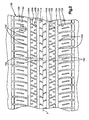
- the tire embodying the present invention includes a molded tread portion.
- the tread portion includes a pair of circumferentially extending ground engaging rib portions. At least one of the rib portions comprises a plurality of circumferentially arranged tread elements.
- Surface means defines a substantially continuous circumferentially extending groove located between the rib portions.
- a broken arch-vent remnant is located between a pair of circumferentially adjacent tread elements. The arch-vent remnant was formed during a tire molding operation by uncured elastomeric rubber flowing into a vent passage connecting the pair of circumferentially adjacent tread elements. The elastomeric material then cured. The cured material in the vent passage breaks during removal of the tire from the tire mold.
- the circumferentially extending groove in the tread portion is free of any arch-vent remnants.
- the present invention further includes a method of removing a plugged vent passage restrictor located in a first end portion of a blind vent passage.
- the method comprises the steps of introducing a substantially incompressible fluid into the vent passage through an unplugged second end portion of the vent passage.
- a tool of a slightly smaller cross-section than the cross-section of a second end portion of the vent passage is placed into the second end portion of the vent passage. The tool contacts the fluid.
- the tool is advanced to transmit sufficient force through the fluid to the plugged vent passage restrictor to then push the restrictor from the first end portion of the vent passage.
- the vacuum molding system 20 includes a tire mold 22 for curing the tire 24.
- the tire mold 22 is operatively connected with a vacuum source (not shown) through suitable piping.
- the operation of the vacuum molding system 20 is disclosed in U.S. Patent No. 4,573,894, the specification of which is incorporated herein by reference.
- the tire mold 22 is a two piece type of mold. It will be apparent that other types of tire mold may equally embody the features of the present invention.
- the tire mold 22 includes upper and lower mold halves 42,44.
- the upper mold half 42 includes a lowermost surface 62 (best seen in Fig. 3).
- the lover mold half 44 includes an uppermost surface 64.
- the mold half 44 includes a register surface 68 which projects approximately .050 inch from the uppermost surface 64.
- the register surface 68 engages the lowermost surface 62 to space apart the lowermost surface 62 from the uppermost surface 64 about .050 inch.
- a plurality of grooves 72 (only one shown) of aproximately .025 inch are machined in the register surface 68.
- the surfaces 62,64 are spaced a slight distance apart as viewed in Fig. 3, when the tire mold 22 is fully closed to define the chamber 66.
- the surfaces 62,64,68 also define a parting line region about which the tire mold halves 42,44 are separable. The parting line region extends in a direction substantially parallel to the mid-circumferential plane P of the tire 24.
- the tire mold halves 42,44 include surfaces which define a cavity 82 (Fig. 1) for receiving and shaping the uncured tire 24.
- the grooves 72 and chamber 66 are in fluid communication with the cavity 82 because the grooves terminate in the cavity.
- a series of passages 84,86,88 are formed in the tire mold 22.
- the passages 84,86,88 are in fluid communication with the vacuum source.
- the passage 86 in the upper mold half 42 fluidly connects the chamber 66 with the vacuum source.
- the cavity 82 is in fluid communication with the vacuum source.
- An elastomeric seal 90 is attached to the mold half 42 and defines the remainder of the chamber 66. The seal 90 effectively closes off the chamber 66 and cavity 82 from the atmospheric pressure immediately adjacent the exterior of the tire mold 22. Thus, as the mold is being closed or is closed, vacuum from the vacuum source can be applied efficiently to the chamber 66, the grooves 72 and the cavity 82.
- the tire mold 22 also includes a tread ring 100 for forming a tread in the tire 24.
- the tread ring 100 includes a plurality of projections 104,106 (Figs. 1, 2 and 3) which define grooves in the tread of the tire 24 at a location other than at the parting line of the tire mold 22.
- Four projections 104 are illustrated, but it will be apparent that any number of projections may be used depending on the desired tread pattern of the tire 24.
- the projections 104 define circumferentially extending grooves 112 (Fig. 6) in the tire 24.
- the axially innermost grooves 112 of the tire 24 define a circumferential and substantially continuous ground engaging central rib 120 in the tread.
- the projections 106 define transversely extending grooves 116 in the tire 24.
- Cooperating projections 104,106 define a plurality of pockets 108,122 (Fig. 2) in the tread ring 100.
- Each pocket 108 defines a respective ground engaging tread element 118 (Fig. 6) on the tire 24.
- Each pocket 122 defines a respective ground engaging tread element 124 on the tire 24.
- a plurality of circumferentially arranged pockets 108,122 are located in the tread ring 100 to define a respective plurality of circumferentially extending ground engaging tread elements 118,124.
- a central pocket 114 (Figs. 2 and 3) is provided in the tire mold 22 to define a continuous circumferentially extending rib 120 (Fig. 6) on the tire 24.
- the central pocket 114 of the tire mold 22 is continually in fluid communication with the chamber 66. Thus, virtually all fluid in the central pocket 114 may be removed during the evacuation cycle.
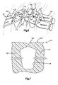
- an arch-vent passage 142 In order to fluidly connect circumferentially adjacent pockets 108 or 122, an arch-vent passage 142, as illustrated in Figs. 4 and 5, is provided.
- the use and design of the arch-vent passage 142 is disclosed in U.S. Patent No. 4,881,881, the specification of which is incorporated herein by reference.
- each pair of circumferentially adjacent pockets 108 or 122 in the tread ring 100 is fluidly connected by a respective arch-vent passage 142, as illustrated in Fig. 2.
- the tire mold 22 also includes a plurality of fluid passages 162 (Figs. 2 and 3).
- the passages 162 fluidly connect each circumferentially arranged pocket 108,122 of the cavity 82 with the chamber 66 and, thus, the vacuum source.
- the fluid passage 162 is a "blind" passage.
- a "blind" passage is defined herein as including a straight passage 164 drilled from the cavity 82 radially outwardly of the tire mold 22.
- Another straight passage 166 is drilled through the surface 62,64, respectively, to intersect the passage 164 at an angle of approximately between 45 and 135 ⁇ .
- the passages 164,166 intersect at essentially a right angle. While just the lower mold half 44 is illustrated in detail as having passages 162,164,166 formed therein, it should be apparent that the upper mold 42 has similar passages.
- the fluid passage 162 enables the evacuation of fluid from each pocket 108,122.
- the fluid passage 162 eliminates the need for an arch-vent passage fluidly connecting any pair of laterally adjacent pockets 108 and 122.
- the tire mold 22 does not require an arch-vent passage to extend through the projections 104 which define the circumferentially extending grooves 112 in the tire 24.
- the tire 24 has no broken arch-vent remnants remaining in any circumferential groove in the tread of the tire 24.
- a broken arch-vent remnant 202 (Fig. 7) occurs when uncured elastomeric material flows into an arch-vent passage 142 during a tire molding operation. The elastomeric material located in the arch-vent 142 then cures. During removal of the tire 24 from the tire mold 22, the cured elastomeric material in the arch-vent passage 142 breaks.
- a tire 24 free of arch-vent remnants in the circumferentially extending grooves not only enhances the appearance of the tire 24 but enables the vacuum molding of tires with relatively wide grooves.
- a restrictor plug 222 (Fig. 3) is located in the end of the passage 164 adjacent the cavity 82.
- the restrictor plug 222 merely reduces the flow area that uncured elastomeric material may flow into.
- a small amount of elastomeric material cures in the restrictor plug 222 to form a vent projection 224 (Fig. 7).
- the presence of only a few circumferentially spaced vent projections 224 extending from the tire 24 does not detract from the overall appearance of the tire. The few vent projections 224 may be readily removed if desired.
- vent passage restrictor plugs 222 sometimes become clogged with cured rubber.
- restrictor plugs were used only in straight passages. It is generally possible to contact a clogged restrictor plug with a tool inserted through the straight passage in the back of the mold and force out the clogged restrictor plug.
- the blind passage arrangement embodying the present invention it is virtually impossible to directly contact a clogged restrictor plug with a suitable tool.
- a method has been devised to remove a clogged restrictor plug from a mold embodying the present invention.
- an incompressible fluid such as oil 246, is placed in the passage 162 associated with the clogged restrictor plug. It may be necessary to reorient the mold half 44 in order to accomplish the effective filling of the passage 162 with oil 246.
- the clogged vent plug restrictor 242 is contacted by the oil 246.
- the oil 246 is preferably used in such quantity that the oil substantially fills at least half the volume of the passage 162.
- a tool 262 (Fig. 9) having a piston like function is then inserted into the unclogged end of the passage 162 at a location away from the clogged restrictor plug 242.
- the tool 262 is then advanced in the passage 162 to pressurize the oil 246.
- the tool is advanced with sufficient force such as by the impact of a hammer 264, so that the oil 246 develops a relatively high fluid pressure within the passage 162.
- the fluid pressure is transferred to the clogged restrictor plug 242 through the oil 246.
- the restrictor plug 242 is forced out of the passage portion 164.
Abstract
Description
- The present invention relates to a tire mold, to a method for molding a tire and to a resulting vehicle tire. In particular, the present invention relates to improvements in vacuum molding the tire.
- Vacuum molding a tire is known. U.S. Patent No. 4,573,894 discloses a tire mold having a cavity for receiving and shaping the tire. The cavity is defined by a surface for contacting the exterior of the tire during a tire curing cycle. The cavity is fluidly connected with a vacuum source for evacuating fluid from within the cavity during the early portion of a tire curing cycle. This evacuation process prevents fluid from becoming trapped between the tire and the surface defining the cavity. Visual defects in the form of voids in the tire exterior are, thus, eliminated. Furthermore, optimal curing contact between the surface defining the cavity and the exterior of the tire results. The advantages of such a vacuum molding system are recognized and are evidenced by the increasing use of vacuum molding in the tire curing art.
- A tire mold cavity typically includes a plurality of projections which define pockets in the mold. The pockets form ground engaging tread elements about the outer circumference of the tire. U.S. Patent No. 4,881,881 discloses an improvement to the vacuum molding system by venting laterally or circumferentially adjacent pockets through specially shaped arch-vent passages formed in the projections. Fluid may communicate between adjacent pockets and then to the vacuum source so the fluid does not become trapped in a pocket. Thus, a ground engaging tread element free from visual defects is provided by the use of arch-vent passages in the vacuum molding system.
- Venting through an arch-vent passage has proved advantageous in a tire production environment. However, the use of the arch-vent passage has practical limitations. On a tire having a groove wider than approximately one-half inch, problems may arise during removal of the cured tire from the tire mold. Such a relatively wide groove is often found extending circumferentially on a performance tire or a light truck tire. The problem arises because an arch-vent remnant formed by cured rubber extending into the arch-vent passage may be sheared off during removal of the cured tire from the mold. This is a particular problem when the arch-vent passage is located in or near a plane extending radially of the tire.
- The sheared-off arch-vent remnant then may fall into the bottom of the cavity in the tire mold. The arch-vent remnant then is cured into the subsequent tire that is placed in the tire mold which results in a visual defect referred to as a blemish. Thus, it will be apparent that it is desirable to produce a tire without any arch-vent remnants extending across such relatively wide and circumferentially extending groove in a tire.
- The present invention is directed to an improved tire mold and to an improved method for vacuum molding a tire that is free from arch-vent remnants in circumferentially extending grooves in the tire. In a tire mold embodying the present invention, a pair of mold parts are separable about cooperating surfaces of the respective mold parts. The cooperating surfaces define a parting line region. Each of the mold parts also includes a surface defining a portion of a cavity for receiving and shaping an uncured tire. Each of the mold parts further includes a plurality of circumferentially arranged pockets associated with the cavity and which define a plurality of circumferentially arranged ground engaging tread elements on the tire.
- The improvement to the tire mold of the present invention comprises vacuum means in fluid communication with the cavity of the tire mold. The vacuum means evacuates fluid from the cavity in the tire mold through a space located between the cooperating surfaces of the respective mold parts. Vent means fluidly connects a pair of circumferentially adjacent pockets. Passage means is associated with one of the mold parts. The passage means provides fluid communication between the vacuum means and one of the pair of circumferentially adjacent pockets which are connected by the vent means.
- In a preferred embodiment of the invention, the tire mold is separable at a location adjacent the mid-circumferential plane of the tire into a pair of mold halves. The passage means comprises a plurality of passages communicating the vacuum means with the respective pockets. The plurality of passages are spaced a substantially equal amount from one another circumferentially about the tire mold halves. The passage means further comprises at least one blind passage formed in a mold half by a pair of drilled openings intersecting at an angle of between 45 and 135` . The vent means comprises an arch-vent passage. A restrictor plug is located in an end portion of the passage means adjacent the cavity.
- The method of molding a tire embodying the present invention comprises providing a tire mold separable into mold halves about cooperating surfaces defining a parting line region. The tire mold includes a surface defining a cavity and a plurality of circumferentially arranged pockets for forming a plurality of ground engaging tread elements in the tire. Fluid is evacuated from the cavity through a chamber at least partially defined by the cooperating surfaces of the mold halves. A pair of circumferentially adjacent pockets are fluidly connected through an arch-vent passage. One of the pair of circumferentially adjacent pockets connected by the arch-vent passage is fluidly connected with the chamber.
- The tire embodying the present invention includes a molded tread portion. The tread portion includes a pair of circumferentially extending ground engaging rib portions. At least one of the rib portions comprises a plurality of circumferentially arranged tread elements. Surface means defines a substantially continuous circumferentially extending groove located between the rib portions. A broken arch-vent remnant is located between a pair of circumferentially adjacent tread elements. The arch-vent remnant was formed during a tire molding operation by uncured elastomeric rubber flowing into a vent passage connecting the pair of circumferentially adjacent tread elements. The elastomeric material then cured. The cured material in the vent passage breaks during removal of the tire from the tire mold. The circumferentially extending groove in the tread portion is free of any arch-vent remnants.
- The present invention further includes a method of removing a plugged vent passage restrictor located in a first end portion of a blind vent passage. The method comprises the steps of introducing a substantially incompressible fluid into the vent passage through an unplugged second end portion of the vent passage. A tool of a slightly smaller cross-section than the cross-section of a second end portion of the vent passage is placed into the second end portion of the vent passage. The tool contacts the fluid. The tool is advanced to transmit sufficient force through the fluid to the plugged vent passage restrictor to then push the restrictor from the first end portion of the vent passage.
- Further features of the present invention will become apparent to those skilled in the art to which the present invention relates from reading the following specification with reference to the accompanying drawings, in which:
- Fig. 1 is a cross-sectional view of a portion of a tire mold embodying the present invention;
- Fig. 2 is a panoramic view of a portion of the tire mold in Fig. 1, taken approximately along line 2-2 in Fig. 1;
- Fig. 3 is an enlarged view of a portion of the tire mold in Fig. 1;
- Fig. 4 is an enlarged side view of an arch-vent of the tire mold in Fig. 2, taken approximately along line 4-4 in Fig. 2;
- Fig. 5 is a plan view of the arch-vent illustrated in Fig. 4, taken along approximately line 5-5 in Fig. 4;
- Fig. 6 is a partial perspective view of a portion of a tire formed in the mold embodying the present invention;
- Fig. 7 is a cross-sectional view of a portion of the tire illustrated in Fig. 6, taken approximately along line 7-7 in Fig. 6;
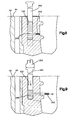
- Fig. 8 is a view similar to Fig. 3, illustrating a plugged vent passage restrictor; and
- Fig. 9 is a view similar to Fig. 8, illustrating removal of the plugged vent passage restrictor from the vent passage.
- A
vacuum molding system 20 embodying the present invention for molding an elastomeric article, such as a tire, is illustrated in Fig. 1. Thevacuum molding system 20 includes atire mold 22 for curing thetire 24. Thetire mold 22 is operatively connected with a vacuum source (not shown) through suitable piping. The operation of thevacuum molding system 20 is disclosed in U.S. Patent No. 4,573,894, the specification of which is incorporated herein by reference. - The
tire mold 22 is a two piece type of mold. It will be apparent that other types of tire mold may equally embody the features of the present invention. Thetire mold 22 includes upper and lower mold halves 42,44. Theupper mold half 42 includes a lowermost surface 62 (best seen in Fig. 3). Thelover mold half 44 includes anuppermost surface 64. - Together, the
surfaces closed chamber 66. Themold half 44 includes aregister surface 68 which projects approximately .050 inch from theuppermost surface 64. Theregister surface 68 engages thelowermost surface 62 to space apart thelowermost surface 62 from theuppermost surface 64 about .050 inch. A plurality of grooves 72 (only one shown) of aproximately .025 inch are machined in theregister surface 68. Thus, thesurfaces tire mold 22 is fully closed to define thechamber 66. Thesurfaces tire 24. - The tire mold halves 42,44 include surfaces which define a cavity 82 (Fig. 1) for receiving and shaping the
uncured tire 24. Thegrooves 72 andchamber 66 are in fluid communication with thecavity 82 because the grooves terminate in the cavity. A series ofpassages tire mold 22. Thepassages - The
passage 86 in theupper mold half 42 fluidly connects thechamber 66 with the vacuum source. Thus, thecavity 82 is in fluid communication with the vacuum source. Anelastomeric seal 90 is attached to themold half 42 and defines the remainder of thechamber 66. Theseal 90 effectively closes off thechamber 66 andcavity 82 from the atmospheric pressure immediately adjacent the exterior of thetire mold 22. Thus, as the mold is being closed or is closed, vacuum from the vacuum source can be applied efficiently to thechamber 66, thegrooves 72 and thecavity 82. - The
tire mold 22 also includes atread ring 100 for forming a tread in thetire 24. Thetread ring 100 includes a plurality of projections 104,106 (Figs. 1, 2 and 3) which define grooves in the tread of thetire 24 at a location other than at the parting line of thetire mold 22. Fourprojections 104 are illustrated, but it will be apparent that any number of projections may be used depending on the desired tread pattern of thetire 24. Theprojections 104 define circumferentially extending grooves 112 (Fig. 6) in thetire 24. The axiallyinnermost grooves 112 of thetire 24 define a circumferential and substantially continuous ground engagingcentral rib 120 in the tread. - The projections 106 (Fig. 2) define transversely extending
grooves 116 in thetire 24. Cooperating projections 104,106 define a plurality of pockets 108,122 (Fig. 2) in thetread ring 100. Eachpocket 108 defines a respective ground engaging tread element 118 (Fig. 6) on thetire 24. Eachpocket 122 defines a respective ground engagingtread element 124 on thetire 24. A plurality of circumferentially arranged pockets 108,122 are located in thetread ring 100 to define a respective plurality of circumferentially extending ground engaging tread elements 118,124. - A central pocket 114 (Figs. 2 and 3) is provided in the
tire mold 22 to define a continuous circumferentially extending rib 120 (Fig. 6) on thetire 24. Thecentral pocket 114 of thetire mold 22 is continually in fluid communication with thechamber 66. Thus, virtually all fluid in thecentral pocket 114 may be removed during the evacuation cycle. - In order to fluidly connect circumferentially
adjacent pockets vent passage 142, as illustrated in Figs. 4 and 5, is provided. The use and design of the arch-vent passage 142 is disclosed in U.S. Patent No. 4,881,881, the specification of which is incorporated herein by reference. Preferably, each pair of circumferentiallyadjacent pockets tread ring 100 is fluidly connected by a respective arch-vent passage 142, as illustrated in Fig. 2. - The
tire mold 22 also includes a plurality of fluid passages 162 (Figs. 2 and 3). Thepassages 162 fluidly connect each circumferentially arranged pocket 108,122 of thecavity 82 with thechamber 66 and, thus, the vacuum source. Preferably, there are at least fourfluid passages 162 which are circumferentially spaced substantially equidistant about thetire mold 22 for each circumferentially arranged plurality ofpockets - The
fluid passage 162 is a "blind" passage. A "blind" passage is defined herein as including astraight passage 164 drilled from thecavity 82 radially outwardly of thetire mold 22. Anotherstraight passage 166 is drilled through thesurface passage 164 at an angle of approximately between 45 and 135` . In the illustrated embodiment, the passages 164,166 intersect at essentially a right angle. While just thelower mold half 44 is illustrated in detail as having passages 162,164,166 formed therein, it should be apparent that theupper mold 42 has similar passages. - During the tire molding operation, vacuum is applied to the
passages chamber 66 andgrooves 72 fluidly communicate thepassage 86 with thepassage 162 so vacuum can also be applied to each pocket 108,122 in thecavity 82. Since each plurality of circumferentially arrangedpockets vent passage 142, all of the pockets are evacuated. - The
fluid passage 162 enables the evacuation of fluid from each pocket 108,122. Thefluid passage 162 eliminates the need for an arch-vent passage fluidly connecting any pair of laterallyadjacent pockets tire mold 22 does not require an arch-vent passage to extend through theprojections 104 which define thecircumferentially extending grooves 112 in thetire 24. - As a result, the
tire 24 has no broken arch-vent remnants remaining in any circumferential groove in the tread of thetire 24. A broken arch-vent remnant 202 (Fig. 7) occurs when uncured elastomeric material flows into an arch-vent passage 142 during a tire molding operation. The elastomeric material located in the arch-vent 142 then cures. During removal of thetire 24 from thetire mold 22, the cured elastomeric material in the arch-vent passage 142 breaks. Atire 24 free of arch-vent remnants in the circumferentially extending grooves not only enhances the appearance of thetire 24 but enables the vacuum molding of tires with relatively wide grooves. - A restrictor plug 222 (Fig. 3) is located in the end of the
passage 164 adjacent thecavity 82. Therestrictor plug 222 merely reduces the flow area that uncured elastomeric material may flow into. A small amount of elastomeric material cures in therestrictor plug 222 to form a vent projection 224 (Fig. 7). The presence of only a few circumferentially spacedvent projections 224 extending from thetire 24 does not detract from the overall appearance of the tire. Thefew vent projections 224 may be readily removed if desired. - It is known in the tire curing industry that vent passage restrictor plugs 222 sometimes become clogged with cured rubber. Formerly, restrictor plugs were used only in straight passages. It is generally possible to contact a clogged restrictor plug with a tool inserted through the straight passage in the back of the mold and force out the clogged restrictor plug. However, it will be apparent with the blind passage arrangement embodying the present invention, it is virtually impossible to directly contact a clogged restrictor plug with a suitable tool.
- Thus, in order for the present invention to be successfully applied to a tire production environment, a method has been devised to remove a clogged restrictor plug from a mold embodying the present invention. To remove a clogged vent passage restrictor plug 242 (Fig. 8) from the
mold half 44, an incompressible fluid, such asoil 246, is placed in thepassage 162 associated with the clogged restrictor plug. It may be necessary to reorient themold half 44 in order to accomplish the effective filling of thepassage 162 withoil 246. The cloggedvent plug restrictor 242 is contacted by theoil 246. Theoil 246 is preferably used in such quantity that the oil substantially fills at least half the volume of thepassage 162. - A tool 262 (Fig. 9) having a piston like function is then inserted into the unclogged end of the
passage 162 at a location away from the cloggedrestrictor plug 242. Thetool 262 is then advanced in thepassage 162 to pressurize theoil 246. The tool is advanced with sufficient force such as by the impact of ahammer 264, so that theoil 246 develops a relatively high fluid pressure within thepassage 162. The fluid pressure is transferred to the cloggedrestrictor plug 242 through theoil 246. When the fluid pressure in theoil 242 increases to a sufficiently high level within thepassage 162, therestrictor plug 242 is forced out of thepassage portion 164. - Care must be taken that the clogged
restrictor plug 242 does not shoot out of thepassage portion 164 like a projectile. A rag is preferably placed over the cloggedrestrictor plug 242 to exert sufficient stopping force on the freedrestrictor plug 242. A new restrictor plug may then be placed in thepassage portion 164 and thetire mold 22 can be placed back into production. - From the above description of preferred embodiments of the invention, those skilled in the art will perceive improvements, changes and modifications. Such improvements, changes and modifications within the skill of the art are intended to be covered by the appended claims.
Claims (18)
Applications Claiming Priority (2)
| Application Number | Priority Date | Filing Date | Title |
|---|---|---|---|
| US07/558,378 US5152951A (en) | 1990-07-27 | 1990-07-27 | Vented tire mold and method for vacuum molding |
| US558378 | 1990-07-27 |
Publications (3)
| Publication Number | Publication Date |
|---|---|
| EP0468154A2 true EP0468154A2 (en) | 1992-01-29 |
| EP0468154A3 EP0468154A3 (en) | 1992-07-08 |
| EP0468154B1 EP0468154B1 (en) | 1996-10-16 |
Family
ID=24229320
Family Applications (1)
| Application Number | Title | Priority Date | Filing Date |
|---|---|---|---|
| EP91107753A Expired - Lifetime EP0468154B1 (en) | 1990-07-27 | 1991-05-14 | Improved tire mold, method and tire |
Country Status (12)
| Country | Link |
|---|---|
| US (1) | US5152951A (en) |
| EP (1) | EP0468154B1 (en) |
| JP (1) | JP3238722B2 (en) |
| KR (1) | KR0147275B1 (en) |
| AT (1) | ATE144178T1 (en) |
| CA (1) | CA2047632C (en) |
| DE (1) | DE69122684T2 (en) |
| DK (1) | DK0468154T3 (en) |
| ES (1) | ES2092526T3 (en) |
| GR (1) | GR3021513T3 (en) |
| MX (1) | MX9100402A (en) |
| SI (1) | SI9110895B (en) |
Cited By (8)
| Publication number | Priority date | Publication date | Assignee | Title |
|---|---|---|---|---|
| WO1994009960A1 (en) * | 1992-11-02 | 1994-05-11 | Wesley-Jessen Corporation | Method for removing excess lens forming material |
| DE19543276C1 (en) * | 1995-11-20 | 1997-02-06 | Continental Ag | Tire vulcanization mold with ventilation |
| EP2202041A1 (en) * | 2008-12-19 | 2010-06-30 | The Goodyear Tire & Rubber Company | Tire mold and method of molding an internal groove in a tire shoulder |
| WO2011073330A1 (en) * | 2009-12-17 | 2011-06-23 | Novartis Ag | Method of separating excess lens forming material from a molded ophthalmic lens, in particular a contact lens |
| CN102107472A (en) * | 2009-12-28 | 2011-06-29 | 住友橡胶工业株式会社 | Mould for tyre |
| CN101607512B (en) * | 2008-06-18 | 2012-09-05 | 青岛黄海橡胶股份有限公司 | Tire tread of sedan meridian tire |
| EP2829376A4 (en) * | 2012-03-21 | 2016-04-27 | Himile Mechanical Science And Technology Shandong Co Ltd | Pore-free tire segmented mold pattern block, segmented mold, and cleaning methods therefor |
| EP3022047A1 (en) * | 2013-07-15 | 2016-05-25 | Bridgestone Americas Tire Operations, LLC | Tire with pre-formed tread and method of making same |
Families Citing this family (7)
| Publication number | Priority date | Publication date | Assignee | Title |
|---|---|---|---|---|
| JP2981423B2 (en) * | 1995-07-10 | 1999-11-22 | 住友ゴム工業株式会社 | Pneumatic tire, method of manufacturing the same, and tire mold used for the same |
| US7399172B2 (en) * | 2004-09-04 | 2008-07-15 | Amerityre | Apparatus for vacuum forming an elastomeric tire |
| US7377596B2 (en) * | 2005-04-29 | 2008-05-27 | Amerityre | Urethane wheel having a metal core |
| US20070063369A1 (en) * | 2005-09-19 | 2007-03-22 | Bridgestone Firestone North American Tire, Llc | Method of molding a tire |
| US7527489B2 (en) * | 2006-05-22 | 2009-05-05 | Amerityre | Apparatus for vacuum forming a tire, wheel or other item from an elastomeric material |
| JP4407773B1 (en) * | 2009-05-07 | 2010-02-03 | 横浜ゴム株式会社 | Pneumatic tire manufacturing method |
| CN114103203A (en) * | 2021-11-22 | 2022-03-01 | 山东豪迈机械科技股份有限公司 | Vacuumizing tire mold |
Citations (5)
| Publication number | Priority date | Publication date | Assignee | Title |
|---|---|---|---|---|
| US1880430A (en) * | 1931-02-14 | 1932-10-04 | Firestone Tire & Rubber Co | Tire mold |
| GB749929A (en) * | 1953-05-13 | 1956-06-06 | Firestone Tire & Rubber Co | Improvements in or relating to tire mold |
| US3692090A (en) * | 1970-07-20 | 1972-09-19 | Goodyear Tire & Rubber | Method of making a vented tire mold |
| DE2210099A1 (en) * | 1972-03-02 | 1973-09-06 | Dunlop Ag | Moulding tyres - and evacuating air between carcase and mould |
| US4078761A (en) * | 1976-09-20 | 1978-03-14 | Thompson Raymond L | Rotational casting mold |
Family Cites Families (5)
| Publication number | Priority date | Publication date | Assignee | Title |
|---|---|---|---|---|
| US4447197A (en) * | 1983-07-25 | 1984-05-08 | The B. F. Goodrich Company | Tire mold with air vent inserts |
| US4573894A (en) * | 1984-11-23 | 1986-03-04 | The B. F. Goodrich Company | Apparatus for ventless tire molding |
| US4662833A (en) * | 1985-05-09 | 1987-05-05 | Corn States Metal Fabricators, Inc. | Venting unit for a rubber article forming mold having vents |
| US4812281A (en) * | 1987-12-14 | 1989-03-14 | The Goodyear Tire & Rubber Company | Pressurization of tire mold vents |
| US4881881A (en) * | 1988-02-08 | 1989-11-21 | The Uniroyal Goodrich Tire Company | Plug-resistant arch-vents for a tire mold |
-
1990
- 1990-07-27 US US07/558,378 patent/US5152951A/en not_active Expired - Lifetime
-
1991
- 1991-05-14 EP EP91107753A patent/EP0468154B1/en not_active Expired - Lifetime
- 1991-05-14 DE DE69122684T patent/DE69122684T2/en not_active Expired - Lifetime
- 1991-05-14 ES ES91107753T patent/ES2092526T3/en not_active Expired - Lifetime
- 1991-05-14 DK DK91107753.5T patent/DK0468154T3/en active
- 1991-05-14 AT AT91107753T patent/ATE144178T1/en active
- 1991-05-21 SI SI9110895A patent/SI9110895B/en unknown
- 1991-07-15 JP JP17411091A patent/JP3238722B2/en not_active Expired - Lifetime
- 1991-07-23 CA CA002047632A patent/CA2047632C/en not_active Expired - Lifetime
- 1991-07-24 KR KR1019910012659A patent/KR0147275B1/en not_active IP Right Cessation
- 1991-07-26 MX MX9100402A patent/MX9100402A/en unknown
-
1996
- 1996-10-31 GR GR960402638T patent/GR3021513T3/en unknown
Patent Citations (5)
| Publication number | Priority date | Publication date | Assignee | Title |
|---|---|---|---|---|
| US1880430A (en) * | 1931-02-14 | 1932-10-04 | Firestone Tire & Rubber Co | Tire mold |
| GB749929A (en) * | 1953-05-13 | 1956-06-06 | Firestone Tire & Rubber Co | Improvements in or relating to tire mold |
| US3692090A (en) * | 1970-07-20 | 1972-09-19 | Goodyear Tire & Rubber | Method of making a vented tire mold |
| DE2210099A1 (en) * | 1972-03-02 | 1973-09-06 | Dunlop Ag | Moulding tyres - and evacuating air between carcase and mould |
| US4078761A (en) * | 1976-09-20 | 1978-03-14 | Thompson Raymond L | Rotational casting mold |
Cited By (14)
| Publication number | Priority date | Publication date | Assignee | Title |
|---|---|---|---|---|
| WO1994009960A1 (en) * | 1992-11-02 | 1994-05-11 | Wesley-Jessen Corporation | Method for removing excess lens forming material |
| DE19543276C1 (en) * | 1995-11-20 | 1997-02-06 | Continental Ag | Tire vulcanization mold with ventilation |
| EP0774333A2 (en) | 1995-11-20 | 1997-05-21 | Continental Aktiengesellschaft | Tyre vulcanizing mould provided with venting means |
| CN101607512B (en) * | 2008-06-18 | 2012-09-05 | 青岛黄海橡胶股份有限公司 | Tire tread of sedan meridian tire |
| US8075294B2 (en) | 2008-12-19 | 2011-12-13 | The Goodyear Tire & Rubber Company | Tire mold and tire with internal grooves in shoulder area |
| EP2202041A1 (en) * | 2008-12-19 | 2010-06-30 | The Goodyear Tire & Rubber Company | Tire mold and method of molding an internal groove in a tire shoulder |
| WO2011073330A1 (en) * | 2009-12-17 | 2011-06-23 | Novartis Ag | Method of separating excess lens forming material from a molded ophthalmic lens, in particular a contact lens |
| US8673187B2 (en) | 2009-12-17 | 2014-03-18 | Novartis Ag | Method of separating excess lens forming material from a molded ophthalmic lens, in particular a contact lens |
| US9914272B2 (en) | 2009-12-17 | 2018-03-13 | Novartis Ag | Method of separating excess lens forming material from a molded ophthalmic lens, in particular a contact lens |
| CN102107472A (en) * | 2009-12-28 | 2011-06-29 | 住友橡胶工业株式会社 | Mould for tyre |
| CN102107472B (en) * | 2009-12-28 | 2016-02-24 | 住友橡胶工业株式会社 | Mold for tire |
| EP2829376A4 (en) * | 2012-03-21 | 2016-04-27 | Himile Mechanical Science And Technology Shandong Co Ltd | Pore-free tire segmented mold pattern block, segmented mold, and cleaning methods therefor |
| EP3022047A1 (en) * | 2013-07-15 | 2016-05-25 | Bridgestone Americas Tire Operations, LLC | Tire with pre-formed tread and method of making same |
| EP3022047A4 (en) * | 2013-07-15 | 2017-03-29 | Bridgestone Americas Tire Operations, LLC | Tire with pre-formed tread and method of making same |
Also Published As
| Publication number | Publication date |
|---|---|
| JPH04226713A (en) | 1992-08-17 |
| DE69122684T2 (en) | 1997-03-06 |
| GR3021513T3 (en) | 1997-01-31 |
| US5152951A (en) | 1992-10-06 |
| MX9100402A (en) | 1992-02-28 |
| ES2092526T3 (en) | 1996-12-01 |
| JP3238722B2 (en) | 2001-12-17 |
| ATE144178T1 (en) | 1996-11-15 |
| SI9110895A (en) | 1994-09-30 |
| DE69122684D1 (en) | 1996-11-21 |
| CA2047632A1 (en) | 1992-01-28 |
| DK0468154T3 (en) | 1996-11-18 |
| SI9110895B (en) | 2001-02-28 |
| KR920002313A (en) | 1992-02-28 |
| CA2047632C (en) | 1998-09-22 |
| EP0468154B1 (en) | 1996-10-16 |
| KR0147275B1 (en) | 1998-08-17 |
| EP0468154A3 (en) | 1992-07-08 |
Similar Documents
| Publication | Publication Date | Title |
|---|---|---|
| US5152951A (en) | Vented tire mold and method for vacuum molding | |
| PL180855B1 (en) | Vented tyre vulcanising mould | |
| EP1256439A3 (en) | Apparatus for producing an unvulcanized rubber element for tires and element obtained thereby | |
| US5059380A (en) | Tire mold vent plug and method | |
| US5349150A (en) | Method of manufacture of a profiled segment | |
| JP3784867B2 (en) | Mold venting device | |
| US4655699A (en) | Reduced flash molding apparatus | |
| US4759701A (en) | Venting unit for a rubber article forming mold having vents | |
| KR100443645B1 (en) | Vent Plug and Tire Curing Mould Mounted with the Same | |
| US5283022A (en) | Restrictor for tire mold vent passage and method of use | |
| EP0594044A1 (en) | Tire mold with venting means | |
| US20070009623A1 (en) | Annular venting of tire tread molds | |
| JPH11207745A (en) | Mold for vulcanizing tire and production of tire using mold | |
| JP2892693B2 (en) | Tire mold | |
| KR200141864Y1 (en) | The structure of air of a mold for modifying a tire | |
| KR100329996B1 (en) | Tire mold for easy venting on the side-wall | |
| KR200144036Y1 (en) | An air exhausting structure of vulcanization mold for a tire | |
| KR0184747B1 (en) | Mold for a tire | |
| US4668456A (en) | Reduced flash molding | |
| KR0139263B1 (en) | Tire mold with an air-hole | |
| EP0916524A3 (en) | Pneumatic radial tires | |
| KR0130063Y1 (en) | Mold for manufacturing a ventless tire | |
| JPH0722321Y2 (en) | Pneumatic tire | |
| GB2304308A (en) | Mould vents | |
| KR200151424Y1 (en) | Vulcanization mold for tire |
Legal Events
| Date | Code | Title | Description |
|---|---|---|---|
| PUAI | Public reference made under article 153(3) epc to a published international application that has entered the european phase |
Free format text: ORIGINAL CODE: 0009012 |
|
| AK | Designated contracting states |
Kind code of ref document: A2 Designated state(s): AT BE CH DE DK ES FR GB GR IT LI LU NL SE |
|
| PUAL | Search report despatched |
Free format text: ORIGINAL CODE: 0009013 |
|
| AK | Designated contracting states |
Kind code of ref document: A3 Designated state(s): AT BE CH DE DK ES FR GB GR IT LI LU NL SE |
|
| 17P | Request for examination filed |
Effective date: 19921231 |
|
| 17Q | First examination report despatched |
Effective date: 19940511 |
|
| RAP1 | Party data changed (applicant data changed or rights of an application transferred) |
Owner name: UNIROYAL GOODRICH LICENSING SERVICES, INC. |
|
| GRAH | Despatch of communication of intention to grant a patent |
Free format text: ORIGINAL CODE: EPIDOS IGRA |
|
| ITF | It: translation for a ep patent filed |
Owner name: DE DOMINICIS & MAYER S.R.L. |
|
| GRAH | Despatch of communication of intention to grant a patent |
Free format text: ORIGINAL CODE: EPIDOS IGRA |
|
| GRAA | (expected) grant |
Free format text: ORIGINAL CODE: 0009210 |
|
| AK | Designated contracting states |
Kind code of ref document: B1 Designated state(s): AT BE CH DE DK ES FR GB GR IT LI LU NL SE |
|
| REF | Corresponds to: |
Ref document number: 144178 Country of ref document: AT Date of ref document: 19961115 Kind code of ref document: T |
|
| REG | Reference to a national code |
Ref country code: CH Ref legal event code: NV Representative=s name: A. KERR AG PATENTANWAELTE |
|
| REG | Reference to a national code |
Ref country code: DK Ref legal event code: T3 |
|
| REF | Corresponds to: |
Ref document number: 69122684 Country of ref document: DE Date of ref document: 19961121 |
|
| REG | Reference to a national code |
Ref country code: ES Ref legal event code: FG2A Ref document number: 2092526 Country of ref document: ES Kind code of ref document: T3 |
|
| REG | Reference to a national code |
Ref country code: GR Ref legal event code: FG4A Free format text: 3021513 |
|
| ET | Fr: translation filed | ||
| PLBE | No opposition filed within time limit |
Free format text: ORIGINAL CODE: 0009261 |
|
| STAA | Information on the status of an ep patent application or granted ep patent |
Free format text: STATUS: NO OPPOSITION FILED WITHIN TIME LIMIT |
|
| 26N | No opposition filed | ||
| PGFP | Annual fee paid to national office [announced via postgrant information from national office to epo] |
Ref country code: SE Payment date: 19980420 Year of fee payment: 8 |
|
| PGFP | Annual fee paid to national office [announced via postgrant information from national office to epo] |
Ref country code: AT Payment date: 19980422 Year of fee payment: 8 Ref country code: DK Payment date: 19980422 Year of fee payment: 8 |
|
| PGFP | Annual fee paid to national office [announced via postgrant information from national office to epo] |
Ref country code: GR Payment date: 19980430 Year of fee payment: 8 Ref country code: NL Payment date: 19980430 Year of fee payment: 8 |
|
| PGFP | Annual fee paid to national office [announced via postgrant information from national office to epo] |
Ref country code: CH Payment date: 19980505 Year of fee payment: 8 |
|
| PGFP | Annual fee paid to national office [announced via postgrant information from national office to epo] |
Ref country code: ES Payment date: 19980520 Year of fee payment: 8 |
|
| PGFP | Annual fee paid to national office [announced via postgrant information from national office to epo] |
Ref country code: LU Payment date: 19980526 Year of fee payment: 8 |
|
| PG25 | Lapsed in a contracting state [announced via postgrant information from national office to epo] |
Ref country code: LU Free format text: LAPSE BECAUSE OF NON-PAYMENT OF DUE FEES Effective date: 19990514 Ref country code: AT Free format text: LAPSE BECAUSE OF NON-PAYMENT OF DUE FEES Effective date: 19990514 |
|
| PG25 | Lapsed in a contracting state [announced via postgrant information from national office to epo] |
Ref country code: SE Free format text: LAPSE BECAUSE OF NON-PAYMENT OF DUE FEES Effective date: 19990515 |
|
| PG25 | Lapsed in a contracting state [announced via postgrant information from national office to epo] |
Ref country code: ES Free format text: LAPSE BECAUSE OF EXPIRATION OF PROTECTION Effective date: 19990517 |
|
| PG25 | Lapsed in a contracting state [announced via postgrant information from national office to epo] |
Ref country code: DK Free format text: LAPSE BECAUSE OF NON-PAYMENT OF DUE FEES Effective date: 19990531 Ref country code: CH Free format text: LAPSE BECAUSE OF NON-PAYMENT OF DUE FEES Effective date: 19990531 Ref country code: LI Free format text: LAPSE BECAUSE OF NON-PAYMENT OF DUE FEES Effective date: 19990531 Ref country code: GR Free format text: LAPSE BECAUSE OF NON-PAYMENT OF DUE FEES Effective date: 19990531 |
|
| PG25 | Lapsed in a contracting state [announced via postgrant information from national office to epo] |
Ref country code: NL Free format text: LAPSE BECAUSE OF NON-PAYMENT OF DUE FEES Effective date: 19991201 |
|
| REG | Reference to a national code |
Ref country code: CH Ref legal event code: PL |
|
| EUG | Se: european patent has lapsed |
Ref document number: 91107753.5 |
|
| NLV4 | Nl: lapsed or anulled due to non-payment of the annual fee |
Effective date: 19991201 |
|
| REG | Reference to a national code |
Ref country code: DK Ref legal event code: EBP |
|
| REG | Reference to a national code |
Ref country code: ES Ref legal event code: FD2A Effective date: 20010601 |
|
| REG | Reference to a national code |
Ref country code: GB Ref legal event code: IF02 |
|
| PGFP | Annual fee paid to national office [announced via postgrant information from national office to epo] |
Ref country code: GB Payment date: 20040505 Year of fee payment: 14 |
|
| PGFP | Annual fee paid to national office [announced via postgrant information from national office to epo] |
Ref country code: BE Payment date: 20040622 Year of fee payment: 14 |
|
| BECH | Be: change of holder |
Owner name: S.A. *MICHELIN RECHERCHE ET TECHNIQUE Effective date: 20050217 |
|
| PG25 | Lapsed in a contracting state [announced via postgrant information from national office to epo] |
Ref country code: IT Free format text: LAPSE BECAUSE OF NON-PAYMENT OF DUE FEES Effective date: 20050514 Ref country code: GB Free format text: LAPSE BECAUSE OF NON-PAYMENT OF DUE FEES Effective date: 20050514 |
|
| PG25 | Lapsed in a contracting state [announced via postgrant information from national office to epo] |
Ref country code: BE Free format text: LAPSE BECAUSE OF NON-PAYMENT OF DUE FEES Effective date: 20050531 |
|
| REG | Reference to a national code |
Ref country code: FR Ref legal event code: CD Ref country code: FR Ref legal event code: TP |
|
| BERE | Be: lapsed |
Owner name: S.A. *MICHELIN RECHERCHE ET TECHNIQUE Effective date: 20050531 |
|
| GBPC | Gb: european patent ceased through non-payment of renewal fee |
Effective date: 20050514 |
|
| BECH | Be: change of holder |
Owner name: S.A. *MICHELIN RECHERCHE ET TECHNIQUE Effective date: 20050217 |
|
| BERE | Be: lapsed |
Owner name: S.A. *MICHELIN RECHERCHE ET TECHNIQUE Effective date: 20050531 |
|
| PGFP | Annual fee paid to national office [announced via postgrant information from national office to epo] |
Ref country code: FR Payment date: 20100525 Year of fee payment: 20 |
|
| PGFP | Annual fee paid to national office [announced via postgrant information from national office to epo] |
Ref country code: DE Payment date: 20100512 Year of fee payment: 20 |
|
| REG | Reference to a national code |
Ref country code: DE Ref legal event code: R071 Ref document number: 69122684 Country of ref document: DE |
|
| PG25 | Lapsed in a contracting state [announced via postgrant information from national office to epo] |
Ref country code: DE Free format text: LAPSE BECAUSE OF EXPIRATION OF PROTECTION Effective date: 20110514 |