EP0773348A1 - Procédé et dispositif pour réchauffer le condensat principal dans une centrale d'énergie - Google Patents
Procédé et dispositif pour réchauffer le condensat principal dans une centrale d'énergie Download PDFInfo
- Publication number
- EP0773348A1 EP0773348A1 EP96114056A EP96114056A EP0773348A1 EP 0773348 A1 EP0773348 A1 EP 0773348A1 EP 96114056 A EP96114056 A EP 96114056A EP 96114056 A EP96114056 A EP 96114056A EP 0773348 A1 EP0773348 A1 EP 0773348A1
- Authority
- EP
- European Patent Office
- Prior art keywords
- steam
- condensate
- low
- heating
- pressure
- Prior art date
- Legal status (The legal status is an assumption and is not a legal conclusion. Google has not performed a legal analysis and makes no representation as to the accuracy of the status listed.)
- Granted
Links
Images

Classifications
-
- F—MECHANICAL ENGINEERING; LIGHTING; HEATING; WEAPONS; BLASTING
- F01—MACHINES OR ENGINES IN GENERAL; ENGINE PLANTS IN GENERAL; STEAM ENGINES
- F01K—STEAM ENGINE PLANTS; STEAM ACCUMULATORS; ENGINE PLANTS NOT OTHERWISE PROVIDED FOR; ENGINES USING SPECIAL WORKING FLUIDS OR CYCLES
- F01K7/00—Steam engine plants characterised by the use of specific types of engine; Plants or engines characterised by their use of special steam systems, cycles or processes; Control means specially adapted for such systems, cycles or processes; Use of withdrawn or exhaust steam for feed-water heating
- F01K7/34—Steam engine plants characterised by the use of specific types of engine; Plants or engines characterised by their use of special steam systems, cycles or processes; Control means specially adapted for such systems, cycles or processes; Use of withdrawn or exhaust steam for feed-water heating the engines being of extraction or non-condensing type; Use of steam for feed-water heating
- F01K7/40—Use of two or more feed-water heaters in series
-
- F—MECHANICAL ENGINEERING; LIGHTING; HEATING; WEAPONS; BLASTING
- F22—STEAM GENERATION
- F22D—PREHEATING, OR ACCUMULATING PREHEATED, FEED-WATER FOR STEAM GENERATION; FEED-WATER SUPPLY FOR STEAM GENERATION; CONTROLLING WATER LEVEL FOR STEAM GENERATION; AUXILIARY DEVICES FOR PROMOTING WATER CIRCULATION WITHIN STEAM BOILERS
- F22D1/00—Feed-water heaters, i.e. economisers or like preheaters
- F22D1/32—Feed-water heaters, i.e. economisers or like preheaters arranged to be heated by steam, e.g. bled from turbines
- F22D1/34—Feed-water heaters, i.e. economisers or like preheaters arranged to be heated by steam, e.g. bled from turbines and returning condensate to boiler with main feed supply
Definitions
- the invention relates to a method for preheating the main condensate in a power plant process with a water vapor circuit, wherein steam is condensed while heating the main condensate in a low pressure preheater and the resulting heating condensate is fed to the main condensate stream.
- the invention further relates to an arrangement for performing this method.
- a steam turbine system in which the heating condensate is preheated in several stages with steam from turbine taps.
- a turbine tap with a higher pressure is connected to a heat exchanger with a higher temperature.
- An additional heat exchanger is connected upstream of each heat exchanger and is connected to the compression side of a steam jet compressor.
- the invention is based on the knowledge that, in particular when planning new power plants, a noticeable improvement in the circuit efficiency and in the cost / utilization ratio in the preheating of feed water can be achieved by suitable process management for preheating the condensate and integrating it into the low-pressure preheating line. This is the object of the invention.
- This object is achieved according to the invention in a method of the type mentioned at the outset in that steam of a higher pressure level than the bleed steam serving as heating steam is fed to a condensate lifter as motive steam and the heating condensate is conveyed from the low-pressure preheater by the condensate lifter into the main condensate stream leaving the preheater .
- the arrangement according to the invention is characterized in that a heating condensate outlet of the low-pressure preheater is connected to a condensate lifter, that a steam connection of the condensate lifter is subjected to steam at higher pressure levels, and that the delivery outlet of the condensate lifter is connected to the main condensate line downstream of the low-pressure preheater is.
- a major advantage of the invention is that saturated water obtained in power plant processes is promoted cavitation-free and extremely economically. Saturated water is produced especially in the low-pressure preheating line in the form of heating condensate; it also occurs when using a steam air preheater. With the same advantages, the invention can be used wherever high pressure change speeds on the suction side of the fluid to be pumped can lead to cavitation of the pumps.
- the residual heat content of the heating condensate can be integrated into the water circuit more thermodynamically more favorably.
- the simple conveying principle of the condensate lifting system makes it possible to dispense with electrical heating condensate pumps and their control.
- the steam serving as motive steam for the condensate lifting system can be removed from the water-steam cycle at a suitable point and after the heating condensate has been pumped back into the water-steam cycle.
- a further improvement in the circuit efficiency can be achieved in a further development of the invention in that a double-chamber low-pressure preheater is used, the first chamber of which is tapped and the second chamber of which is a vapor mixture obtained by thermocompression.
- the low-pressure preheating line 1 shown in the circuit diagram according to FIG. 1 has low-pressure preheaters NDV 1a / 1b and NDV 2a / 2b, four condensate lifters 50, 51, 52 and 53 and a motive steam busbar 20.
- the preheaters NDV 1a and NDV 2a are fed with steam from taps A1 and A2 of a low-pressure turbine 5.
- the condensate conveyed in the exemplary embodiment shown by a main condensate pump 2 is preheated in several stages in the LP preheating line 1 and conveyed via a main condensate line 3 into a feed water tank (not shown).
- the steam removed from the motive steam busbar 20 serves as condensed steam for the condensate lifters 50 ... 53. That steam is then reintroduced into the water-steam cycle at a suitable point.
- the first preheating stage NDV 1a is supplied with largely relaxed steam from tap A1. Heating condensate accumulating in the NDV 1a is fed to the condensate lifter 50 via a line 10 and is conveyed by the latter to the main condensate stream 3 via a line 11.
- the second preheating stage NDV 1b receives a steam mixture from a steam jet 30, to which steam from the tap A2 is fed via a motive steam connection 31 and which sucks in the exergetically inferior steam from the tap A1 via a suction steam connection 32.
- the condensation temperature is raised by compressing the sucked-in steam in the steam jet 30.
- the heating condensate obtained in the NDV 1b stage is fed to the condensate lifter 51 via a line 12 and is conveyed by the latter to the main condensate stream 3 via a line 13.
- the integration of the downstream preheating stages NDV 2a and NDV 2b, their application of bleed steam and the cavitation-free pumping of saturated water by means of the condensate lifters 52 and 53 are analogous.
- the motive steam for the condensate lifters 52 and 53 is also taken from the motive steam busbar 20.
- the preheating stage NDV 2a receives steam from tap A2.
- the heating condensate from the preheating stage NDV 2a is fed via line 14 to the condensate siphon 52 and is conveyed by this via line 15 into the main condensate stream 3.
- the next stage NDV 2b is supplied with a steam mixture from a steam jet 40, the motive steam connection 31 of which is connected to a tap A3 and which sucks in steam from the tap A2 via a suction steam connection 42.
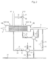
- the double-chamber preheater shown in FIG. 2 is of a known type in the exemplary embodiment described.
- the main condensate enters from the main condensate line 3 into an inlet-side water chamber 4a, is in a first heat exchanger chamber (preheating stage NDV 1a) with bleed steam A1 and in a second heat exchanger chamber (preheating stage NDV 1b), which is closed in a pressure-tight manner by the first heat exchanger chamber, with the steam mixture from the steam jet 30 and finally flows via an outlet-side water chamber 4b into a subsequent section of the main condensate line 3.
- bleed steam A1 is sucked in by the driving steam from A2 by pulse exchange and flows into the NDV 1b after pressure increase in the diffuser.
- the heating condensate obtained in the NDV 1a is passed through a shut-off valve 60 and a check valve 61 via line 10 into the condensate lifter 50.
- a float is mounted in the condensate lifter, which controls a motive steam inlet valve 64 and a steam outlet valve 65 in opposite directions via a lever arrangement. The last two valves are integrated in the condensate lifter.
- the heating condensate flows from the NDV 1a into the condensate lifter 50.
- the rising condensate level in the interior of the condensate lifter lifts the float.
- the latter opens the motive steam inlet valve 64 in its upper limit position via a linkage.
- the motive steam flowing in from the busbar 20 via the motive steam line 21 now presses the heating condensate via the check valve 62 arranged in line 11 and the shut-off valve 63 into the main condensate line 3.
- the float closes the motive steam inlet valve 64 and opens the outlet valve 65.
- the steam flowing out via line 22 clears the way for condensate flowing in from NDV 1a.
- the system consisting of NDV 1b and condensate lifter 51 is constructed analogously and works accordingly.
Landscapes
- Engineering & Computer Science (AREA)
- Mechanical Engineering (AREA)
- General Engineering & Computer Science (AREA)
- Chemical & Material Sciences (AREA)
- Combustion & Propulsion (AREA)
- Physics & Mathematics (AREA)
- Thermal Sciences (AREA)
- Jet Pumps And Other Pumps (AREA)
- Control Of Turbines (AREA)
- Engine Equipment That Uses Special Cycles (AREA)
Applications Claiming Priority (2)
| Application Number | Priority Date | Filing Date | Title |
|---|---|---|---|
| DE19541543A DE19541543C2 (de) | 1995-11-08 | 1995-11-08 | Verfahren und Anordnung zum Vorwärmen des Hauptkondensats in Kraftwerksprozessen |
| DE19541543 | 1995-11-08 |
Publications (2)
| Publication Number | Publication Date |
|---|---|
| EP0773348A1 true EP0773348A1 (fr) | 1997-05-14 |
| EP0773348B1 EP0773348B1 (fr) | 2001-03-14 |
Family
ID=7776875
Family Applications (1)
| Application Number | Title | Priority Date | Filing Date |
|---|---|---|---|
| EP96114056A Expired - Lifetime EP0773348B1 (fr) | 1995-11-08 | 1996-09-03 | Procédé et dispositif pour réchauffer le condensat principal dans une centrale d'énergie |
Country Status (3)
| Country | Link |
|---|---|
| EP (1) | EP0773348B1 (fr) |
| AT (1) | ATE199763T1 (fr) |
| DE (2) | DE19541543C2 (fr) |
Cited By (2)
| Publication number | Priority date | Publication date | Assignee | Title |
|---|---|---|---|---|
| WO2006048505A1 (fr) * | 2004-11-03 | 2006-05-11 | Wärtsilä Finland Oy | Procédé et système de récupération thermique |
| WO2013000720A3 (fr) * | 2011-06-28 | 2013-12-19 | Siemens Aktiengesellschaft | Prélèvement régulé supplémentaire destiné à un préchauffeur pour améliorer la dynamique de l'installation et la régulation de fréquence dans une centrale thermique à vapeur |
Families Citing this family (1)
| Publication number | Priority date | Publication date | Assignee | Title |
|---|---|---|---|---|
| DE19806238C1 (de) * | 1998-02-16 | 1999-04-15 | Steag Ag | Wärmetauscheranordnung |
Citations (2)
| Publication number | Priority date | Publication date | Assignee | Title |
|---|---|---|---|---|
| US3238729A (en) * | 1962-07-23 | 1966-03-08 | Ass Elect Ind | Steam turbine power plants |
| JPS61126309A (ja) * | 1984-11-22 | 1986-06-13 | Toshiba Corp | 蒸気発電プラント |
Family Cites Families (2)
| Publication number | Priority date | Publication date | Assignee | Title |
|---|---|---|---|---|
| DE1551263A1 (de) * | 1965-03-01 | 1969-05-29 | Steinmueller Gmbh L & C | Kreisprozess fuer Dampfkraftanlagen |
| DE3616797A1 (de) * | 1986-05-17 | 1987-11-19 | Koerting Ag | Dampfturbinenanlage |
-
1995
- 1995-11-08 DE DE19541543A patent/DE19541543C2/de not_active Expired - Fee Related
-
1996
- 1996-09-03 DE DE59606584T patent/DE59606584D1/de not_active Expired - Lifetime
- 1996-09-03 EP EP96114056A patent/EP0773348B1/fr not_active Expired - Lifetime
- 1996-09-03 AT AT96114056T patent/ATE199763T1/de active
Patent Citations (2)
| Publication number | Priority date | Publication date | Assignee | Title |
|---|---|---|---|---|
| US3238729A (en) * | 1962-07-23 | 1966-03-08 | Ass Elect Ind | Steam turbine power plants |
| JPS61126309A (ja) * | 1984-11-22 | 1986-06-13 | Toshiba Corp | 蒸気発電プラント |
Non-Patent Citations (2)
| Title |
|---|
| PATENT ABSTRACTS OF JAPAN vol. 010, no. 320 (M - 530) 30 October 1986 (1986-10-30) * |
| W. O'KEEFE: "Be aware of pumpless methods for returning condensate", POWER, vol. 137, no. 10, October 1993 (1993-10-01), NEW YORK US, pages 83 - 84, XP000400297 * |
Cited By (2)
| Publication number | Priority date | Publication date | Assignee | Title |
|---|---|---|---|---|
| WO2006048505A1 (fr) * | 2004-11-03 | 2006-05-11 | Wärtsilä Finland Oy | Procédé et système de récupération thermique |
| WO2013000720A3 (fr) * | 2011-06-28 | 2013-12-19 | Siemens Aktiengesellschaft | Prélèvement régulé supplémentaire destiné à un préchauffeur pour améliorer la dynamique de l'installation et la régulation de fréquence dans une centrale thermique à vapeur |
Also Published As
| Publication number | Publication date |
|---|---|
| DE19541543A1 (de) | 1997-07-03 |
| DE19541543C2 (de) | 1997-10-16 |
| EP0773348B1 (fr) | 2001-03-14 |
| ATE199763T1 (de) | 2001-03-15 |
| DE59606584D1 (de) | 2001-04-19 |
Similar Documents
| Publication | Publication Date | Title |
|---|---|---|
| DE19736889C1 (de) | Verfahren zum Betreiben einer Gas- und Dampfturbinenanlage und Gas- und Dampfturbinenanlage zur Durchführung des Verfahrens | |
| DE102004020753A1 (de) | Vorrichtung zur Ausnutzung der Abwärme von Verdichtern | |
| DE19513285A1 (de) | Turbinen-Antrieb für Kesselspeisepumpe / Speisewasser-Leitungssystem | |
| DE3616797C2 (fr) | ||
| EP0633978A1 (fr) | Procede et dispositif permettant de faire fonctionner le circuit eau-vapeur d'une centrale thermo-electrique | |
| EP0851971B1 (fr) | Procede et dispositif de prechauffage de l'eau d'alimentation d'un generateur de vapeur dans les processus de centrales electriques | |
| EP0037845B1 (fr) | Centrale combinée de turbines à gaz et à vapeur | |
| DE3719861C2 (de) | Dampfturbinenanlage | |
| EP1055801B1 (fr) | Procédé pour faire fonctionner une centrale à vapeur | |
| EP0773348B1 (fr) | Procédé et dispositif pour réchauffer le condensat principal dans une centrale d'énergie | |
| DE19943782C2 (de) | Gas- und Dampfturbinenanlage | |
| EP1254302B1 (fr) | Procede et dispositif permettant de produire le vide dans le condensateur de turbine | |
| DE2425794A1 (de) | Dampfkraftanlage mit speisewasservorwaermung durch anzapfdampf | |
| DE3524882C1 (de) | Verfahren zum Betreiben einer Heizkraftwerksanlage zur Fernwärme- und Stromerzeugung | |
| DE2243380C3 (de) | Dampfkraftanlage mit rauchgasbeheiztem Speisewasservorwärmer und wasserbeheiztem Luftvorwärmer | |
| DE1801042A1 (de) | Dampfkraftanlage mit aufgeladenem Dampferzeuger | |
| DE451350C (de) | Dampfturbinenanlage mit Vorwaermung des Speisewassers und einer mit Abzapfdampf betriebenen Hilfsturbine | |
| DE19736888A1 (de) | Verfahren zum Betreiben eines Durchlaufdampferzeugers und Durchlaufdampferzeuger zur Durchführung des Verfahrens sowie Gas- und Dampfturbinenanlage | |
| DE4441008A1 (de) | Anlage zur Dampferzeugung nach dem Naturumlaufprinzip und Verfahren zum Anstoß des Wasserumlaufs in einer derartigen Anlage | |
| DE102011114776B4 (de) | Verfahren zum Betreiben eines Dampfkraftwerkes | |
| EP0256243A1 (fr) | Centrale de turbines à vapeur | |
| EP1056975B1 (fr) | Systeme d'echange thermique | |
| AT18796B (de) | Schleuderpumpenanlage mit Dampfturbinenantrieb. | |
| DE600093C (de) | Zweidruckdampfkraftanlage | |
| AT402215B (de) | Vorrichtung zur überführung eines offenen hydraulischen systems in ein teilweise geschlossenes system |
Legal Events
| Date | Code | Title | Description |
|---|---|---|---|
| PUAI | Public reference made under article 153(3) epc to a published international application that has entered the european phase |
Free format text: ORIGINAL CODE: 0009012 |
|
| 17P | Request for examination filed |
Effective date: 19970306 |
|
| AK | Designated contracting states |
Kind code of ref document: A1 Designated state(s): AT DE DK ES FR GB GR IE NL PT |
|
| 17Q | First examination report despatched |
Effective date: 19990202 |
|
| RAP1 | Party data changed (applicant data changed or rights of an application transferred) |
Owner name: STEAG ENCOTEC GMBH |
|
| GRAG | Despatch of communication of intention to grant |
Free format text: ORIGINAL CODE: EPIDOS AGRA |
|
| GRAG | Despatch of communication of intention to grant |
Free format text: ORIGINAL CODE: EPIDOS AGRA |
|
| GRAH | Despatch of communication of intention to grant a patent |
Free format text: ORIGINAL CODE: EPIDOS IGRA |
|
| GRAH | Despatch of communication of intention to grant a patent |
Free format text: ORIGINAL CODE: EPIDOS IGRA |
|
| GRAA | (expected) grant |
Free format text: ORIGINAL CODE: 0009210 |
|
| AK | Designated contracting states |
Kind code of ref document: B1 Designated state(s): AT DE DK ES FR GB GR IE NL PT |
|
| PG25 | Lapsed in a contracting state [announced via postgrant information from national office to epo] |
Ref country code: NL Free format text: LAPSE BECAUSE OF FAILURE TO SUBMIT A TRANSLATION OF THE DESCRIPTION OR TO PAY THE FEE WITHIN THE PRESCRIBED TIME-LIMIT Effective date: 20010314 Ref country code: IE Free format text: LAPSE BECAUSE OF FAILURE TO SUBMIT A TRANSLATION OF THE DESCRIPTION OR TO PAY THE FEE WITHIN THE PRESCRIBED TIME-LIMIT Effective date: 20010314 Ref country code: GB Free format text: LAPSE BECAUSE OF FAILURE TO SUBMIT A TRANSLATION OF THE DESCRIPTION OR TO PAY THE FEE WITHIN THE PRESCRIBED TIME-LIMIT Effective date: 20010314 Ref country code: FR Free format text: LAPSE BECAUSE OF FAILURE TO SUBMIT A TRANSLATION OF THE DESCRIPTION OR TO PAY THE FEE WITHIN THE PRESCRIBED TIME-LIMIT Effective date: 20010314 |
|
| REF | Corresponds to: |
Ref document number: 199763 Country of ref document: AT Date of ref document: 20010315 Kind code of ref document: T |
|
| REG | Reference to a national code |
Ref country code: IE Ref legal event code: FG4D Free format text: GERMAN |
|
| REF | Corresponds to: |
Ref document number: 59606584 Country of ref document: DE Date of ref document: 20010419 |
|
| PG25 | Lapsed in a contracting state [announced via postgrant information from national office to epo] |
Ref country code: DK Free format text: LAPSE BECAUSE OF FAILURE TO SUBMIT A TRANSLATION OF THE DESCRIPTION OR TO PAY THE FEE WITHIN THE PRESCRIBED TIME-LIMIT Effective date: 20010614 |
|
| PG25 | Lapsed in a contracting state [announced via postgrant information from national office to epo] |
Ref country code: PT Free format text: LAPSE BECAUSE OF FAILURE TO SUBMIT A TRANSLATION OF THE DESCRIPTION OR TO PAY THE FEE WITHIN THE PRESCRIBED TIME-LIMIT Effective date: 20010615 Ref country code: GR Free format text: LAPSE BECAUSE OF FAILURE TO SUBMIT A TRANSLATION OF THE DESCRIPTION OR TO PAY THE FEE WITHIN THE PRESCRIBED TIME-LIMIT Effective date: 20010615 |
|
| NLV1 | Nl: lapsed or annulled due to failure to fulfill the requirements of art. 29p and 29m of the patents act | ||
| EN | Fr: translation not filed | ||
| GBV | Gb: ep patent (uk) treated as always having been void in accordance with gb section 77(7)/1977 [no translation filed] |
Effective date: 20010314 |
|
| PG25 | Lapsed in a contracting state [announced via postgrant information from national office to epo] |
Ref country code: ES Free format text: LAPSE BECAUSE OF FAILURE TO SUBMIT A TRANSLATION OF THE DESCRIPTION OR TO PAY THE FEE WITHIN THE PRESCRIBED TIME-LIMIT Effective date: 20010927 |
|
| REG | Reference to a national code |
Ref country code: IE Ref legal event code: FD4D |
|
| PLBE | No opposition filed within time limit |
Free format text: ORIGINAL CODE: 0009261 |
|
| STAA | Information on the status of an ep patent application or granted ep patent |
Free format text: STATUS: NO OPPOSITION FILED WITHIN TIME LIMIT |
|
| 26N | No opposition filed | ||
| PGFP | Annual fee paid to national office [announced via postgrant information from national office to epo] |
Ref country code: AT Payment date: 20100914 Year of fee payment: 15 |
|
| PGFP | Annual fee paid to national office [announced via postgrant information from national office to epo] |
Ref country code: DE Payment date: 20100729 Year of fee payment: 15 |
|
| REG | Reference to a national code |
Ref country code: DE Ref legal event code: R119 Ref document number: 59606584 Country of ref document: DE Effective date: 20120403 |
|
| PG25 | Lapsed in a contracting state [announced via postgrant information from national office to epo] |
Ref country code: DE Free format text: LAPSE BECAUSE OF NON-PAYMENT OF DUE FEES Effective date: 20120403 |
|
| REG | Reference to a national code |
Ref country code: AT Ref legal event code: MM01 Ref document number: 199763 Country of ref document: AT Kind code of ref document: T Effective date: 20110903 |
|
| PG25 | Lapsed in a contracting state [announced via postgrant information from national office to epo] |
Ref country code: AT Free format text: LAPSE BECAUSE OF NON-PAYMENT OF DUE FEES Effective date: 20110903 |