EP0773339A1 - Türscharnier für ein Kraftfahrzeug - Google Patents
Türscharnier für ein Kraftfahrzeug Download PDFInfo
- Publication number
- EP0773339A1 EP0773339A1 EP96307294A EP96307294A EP0773339A1 EP 0773339 A1 EP0773339 A1 EP 0773339A1 EP 96307294 A EP96307294 A EP 96307294A EP 96307294 A EP96307294 A EP 96307294A EP 0773339 A1 EP0773339 A1 EP 0773339A1
- Authority
- EP
- European Patent Office
- Prior art keywords
- vehicle
- hinge
- door
- impact
- male
- Prior art date
- Legal status (The legal status is an assumption and is not a legal conclusion. Google has not performed a legal analysis and makes no representation as to the accuracy of the status listed.)
- Withdrawn
Links
Images


Classifications
-
- E—FIXED CONSTRUCTIONS
- E05—LOCKS; KEYS; WINDOW OR DOOR FITTINGS; SAFES
- E05D—HINGES OR SUSPENSION DEVICES FOR DOORS, WINDOWS OR WINGS
- E05D11/00—Additional features or accessories of hinges
-
- E—FIXED CONSTRUCTIONS
- E05—LOCKS; KEYS; WINDOW OR DOOR FITTINGS; SAFES
- E05D—HINGES OR SUSPENSION DEVICES FOR DOORS, WINDOWS OR WINGS
- E05D11/00—Additional features or accessories of hinges
- E05D2011/009—Impact absorbing hinges for vehicle doors
-
- E—FIXED CONSTRUCTIONS
- E05—LOCKS; KEYS; WINDOW OR DOOR FITTINGS; SAFES
- E05Y—INDEXING SCHEME ASSOCIATED WITH SUBCLASSES E05D AND E05F, RELATING TO CONSTRUCTION ELEMENTS, ELECTRIC CONTROL, POWER SUPPLY, POWER SIGNAL OR TRANSMISSION, USER INTERFACES, MOUNTING OR COUPLING, DETAILS, ACCESSORIES, AUXILIARY OPERATIONS NOT OTHERWISE PROVIDED FOR, APPLICATION THEREOF
- E05Y2900/00—Application of doors, windows, wings or fittings thereof
- E05Y2900/50—Application of doors, windows, wings or fittings thereof for vehicles
- E05Y2900/53—Type of wing
- E05Y2900/531—Doors
Definitions
- the present invention relates to a door hinge for a vehicle, and more particularly to a door hinge for a vehicle which is provided with an impact absorbing capability.
- a conventional door hinge for a vehicle is generally constructed as shown in Fig. 7 (Japanese Patent Application Laid-Open No. 4-81322), in which a male 106 of a hinge 104 is secured to a vehicle outer side wall portion 102A of an outer panel 102 of a pillar 100 by means of bolts 108 and nuts 110. Further, a female 112 of the hinge 104 is secured to a vehicle front side wall portion 116A of an inner panel 116 of a side door 114 by means of bolts 118 and nuts 120. The male 106 and the female 112 of the hinge 104 are pivotally supported by means of a shaft 122.
- a door hinge for a vehicle for connecting a door to a vehicle body comprising: an impact absorbing portion adapted to be deformed by an impact acting in a transverse direction of the vehicle so as to absorb the impact, the impact absorbing portion being provided at a connecting portion for connecting the vehicle body and the door.
- the impact absorbing portion is deformed and absorbs the impact.
- the door hinge for a vehicle according to the first aspect of the invention, is comprised of a hinge male and a hinge female, and the impact absorbing portion which is adapted to be deformed by the impact acting in the transverse direction of the vehicle so as to absorb the impact is provided on at least one of the hinge male and the hinge female.
- the impact absorbing portion is deformed and absorbs the impact.
- a point of application of a load and a support point of the impact absorbing portion are offset from each other, and the shape of a portion of the impact absorbing portion lying between the point of application of a load and the support point is curved in such a manner as to protrude in a direction away from the door.
- the impact absorbing portion is deformed in a direction in which the impact absorbing portion does not interfere with the door, so as to absorb the impact.
- the shape of the impact absorbing portion is curved in a vertical direction of the vehicle.
- the impact absorbing portion becomes further curved in the vertical direction of the vehicle, and absorbs the impact.
- the impact absorbing portion is constituted by a proximal portion, a hinge portion separated from the proximal portion, connecting means for connecting the hinge portion and the proximal portion, and a guide portion for guiding the connecting means during application of an impact and for relatively moving the hinge portion and the proximal portion in a direction in which the impact is absorbed.
- the connecting means is guided by the guide portion, and the hinge portion and the proximal portion are relatively moved in the direction in the impact-absorbing direction, so as to absorb the impact.
- arrow FR denotes a forward direction of the vehicle
- arrow UP denotes an upward direction of the vehicle
- arrow IN denotes a transversely inward direction of the vehicle.
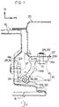
- a door hinge 10 for a vehicle in accordance with the first embodiment is comprised of a female 12 and a male 14.
- the female 12 is secured to a vehicle front side vertical wall portion 18A of a side door inner panel 18 which constitutes a vehicle compartment inner side portion of a side door 16.
- the male 14 is secured to a vehicle outer side vertical wall portion 22A of a central pillar outer panel 22 which constitutes a vehicle outer side portion of a central pillar 20.
- a pair of attaching holes 24 and 26 are formed in an attaching portion 14A of the male 14 in a vertical row at a predetermined interval therebetween.
- the male 14 is secured to the vehicle outer side vertical wall portion 22A of the central pillar outer panel 22 by means of bolts 31 inserted in the attaching holes 24 and 26.
- a connecting portion 14B serving as an impact absorbing portion is provided uprightly on the attaching portion 14A of the male 14.
- the cross-sectional shape of the connecting portion 14B is formed in a rectangular shape whose longitudinal direction is set as a vertical direction, as indicated by a hatched portion E in Fig. 2.
- a through hole 15 is formed at a distal end portion of the connecting portion 14B in such a manner as to extend in the vertical direction.
- a pair of attaching holes 28 and 30 are formed in an attaching portion 12A of the female 12 in a vertical row at a predetermined interval therebetween.
- the female 12 is secured to the vehicle front side vertical wall portion 18A of the side door inner panel 18 by means of bolts 27 inserted in the attaching holes 28 and 30.
- a vertical pair of bearing portions 12B and 12C are provided uprightly on the attaching portion 12A of the female 12.
- Through holes 32 and 34 are respectively formed in the bearing portions 12B and 12C in such a manner as to extend in the vertical direction.
- a shaft 36 is inserted in the through hole 15 of the male 14 and the through holes 32 and 34 of the female 12.
- the arrangement provided is such that the male 14 and the female 12 rotate relative to each other with this shaft 36 as a center of rotation, so as to open or close the side door 16.
- the center of the through hole 15 of the connecting portion 14B serves as a point P1 of application of a load, while a basal portion of the connecting portion 14B serves as a support point P2.
- the point P1 of application of a load and the support point P2 are offset from each other (with an offset amount L) in the longitudinal direction of the vehicle, and a portion of the connecting portion 14B lying between the point P1 of application of a load and the support point P2 is curved in a direction away from the vehicle front side vertical wall portion 18A of the side door inner panel 18, i.e., in such a manner as to protrude toward the front side of the vehicle.
- the connecting portion 14B of the male 14 is pressed and becomes further curved in such a manner as to protrude further in the forward direction of the vehicle, as shown by the phantom lines in Fig. 1. Consequently, the side door 16 moves toward the inner side in the transverse direction of the vehicle, and assumes the position indicated by the phantom lines in Fig. 1.
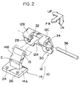
- a door hinge 40 for a vehicle in accordance with the second embodiment is comprised of a female 42 and a male 44.
- a pair of attaching holes 46 and 48 are formed in an attaching portion 44A of the male 44 in a vertical row at a predetermined interval therebetween.
- the male 44 is secured to the side door inner panel 18 by means of bolts 50 inserted in the attaching holes 46 and 48.
- a bearing portion 44B is provided uprightly on the attaching portion 44A of the male 44, and a through hole 52 is formed in the bearing portion 44B in such a manner as to extend in the vertical direction.
- a pair of attaching holes 54 and 56 are formed in an attaching portion 42A of the female 42 at a predetermined interval therebetween in the longitudinal direction of the vehicle.
- the female 42 is secured to the central pillar outer panel 22 by means of bolts 57 inserted in the attaching holes 54 and 56.
- a vertical pair of connecting portions 42B and 42C serving as impact absorbing portions are provided uprightly on the attaching portion 42A of the female 42.
- Through holes 58 and 60 are respectively formed at distal end portions of the connecting portions 42B and 42C.
- a shaft 62 is inserted in the through hole 52 of the male 44 and the through holes 58 and 60 of the female 42.
- the arrangement provided is such that the male 44 and the female 42 rotate relative to each other with this shaft 62 as a center of rotation, so as to open or close the side door 16.
- the connecting portion 42B of the female 42 is inclined in a diagonally downward direction of the vehicle from an intermediate portion thereof toward a distal end portion thereof (on the right-hand side in Fig. 3).
- the connecting portion 42C of the female 42 is inclined in a diagonally upward direction of the vehicle from an intermediate portion thereof toward a distal end portion thereof (on the right-hand side in Fig. 3).
- the connecting portions 42B and 42C of the female 42 are bent in such a manner as to protrude toward the outer side of the vehicle, as shown by the phantom lines in Fig. 3.
- the connecting portions 42B and 42C of the female 42 are bent in such a manner as to protrude toward the outer side of the vehicle, as shown by the phantom lines in Fig. 3. Consequently, the side door 16 moves toward the inner side in the transverse direction of the vehicle, and assumes the position indicated by the phantom lines in Fig. 3.
- the same component parts as those of the first embodiment will be denoted by the same reference numerals, and a description thereof will be omitted.
- a door hinge 70 for a vehicle in accordance with the third embodiment is comprised of a female 72 and a male 74.
- a pair of attaching holes 76 and 78 are formed in an attaching portion 74A of the male 74 in a vertical row at a predetermined interval therebetween.
- the male 74 is secured to the vehicle outer side vertical wall portion 22A of the central pillar outer panel 22 by means of bolts 80 inserted in the attaching holes 76 and 78.
- a proximal portion 74B serving as a part of the impact absorbing portion is provided uprightly on the attaching portion 74A of the male 74, and an elongated hole 82 serving as a guide portion extending in the transverse direction of the vehicle is formed in a central portion of the proximal portion 74B.
- An outer side, as viewed in the transverse direction of the vehicle, of the elongated hole 82 serves as a bolt attaching portion 82A, while an inner side, as viewed in the transverse direction of the vehicle, of the elongated hole 82 serves as a narrow guide slit 82B.
- a stepped screw 84 serving as a connecting means is inserted in the bolt attaching portion 82A of the elongated hole 82, and the stepped screw 84 is threadedly engaged in a threaded hole 87 formed in a hinge portion 86.
- the hinge portion 86 is formed separately from the male 74, and together with the proximal portion 74B constitutes an impact absorbing portion.
- the arrangement provided is such that in a case where a load of a predetermined value or more is applied to the male 74 and the hinge portion 86 in the transverse direction of the vehicle (in the directions arrows A and B in Fig. 6), the stepped screw 84 and the guide slit 82B move relative to each other, so that the male 74 and the hinge portion 86 move relative to each other in the transverse direction of the vehicle.
- a through hole 88 is formed in a distal end portion 86A of the hinge portion 86 in such a manner as to extend in the vertical direction.
- a pair of attaching holes 90 and 92 are formed in an attaching portion 72A of the female 72 in a vertical row at a predetermined interval therebetween.
- the female 72 is secured to the vehicle front side vertical wall portion 18A of the side door inner panel 18 by means of bolts 95 inserted in the attaching holes 90 an 92, as shown in Fig. 5.
- a vertical pair of bearing portions 72B and 72C are provided uprightly on the attaching portion 72A of the female 72, and through holes 94 and 96 are respectively formed on the bearing portions 72B and 72C in such a manner as to extend in the vertical direction.
- a shaft 98 is inserted in the through hole 88 of the hinge portion 86 of the male 74 and the through holes 94 and 96 of the bearing portions 72B and 72C of the female 72, and the male 74 and the female 72 rotate relative to each other with the shaft 98 as a center of rotation, so as to open or close the side door 16.
- the stepped screw 84 and the guide slit 82B move relative to each other, so that the male 74 and the hinge portion 86 move relative to each other in the transverse direction of the vehicle. Consequently, the side door 16 moves toward the inner side in the transverse direction of the vehicle, and assumes the position indicated by the phantom lines in Fig. 5.
- an arrangement may be provided such that at least one of a male attaching portion for attaching a hinge male and a female attaching portion for attaching a hinge female is provided with an impact absorbing portion whereby at least one of the relative positions of the male attaching portion and the hinge male and the relative positions of the female attaching portion and the hinge female is changed due to an impact acting in the transverse direction of the vehicle, so as to absorb the impact.
Landscapes
- Engineering & Computer Science (AREA)
- Mechanical Engineering (AREA)
- Body Structure For Vehicles (AREA)
- Hinge Accessories (AREA)
Applications Claiming Priority (2)
| Application Number | Priority Date | Filing Date | Title |
|---|---|---|---|
| JP288598/95 | 1995-11-07 | ||
| JP7288598A JPH09132033A (ja) | 1995-11-07 | 1995-11-07 | 自動車用ドアヒンジ |
Publications (1)
| Publication Number | Publication Date |
|---|---|
| EP0773339A1 true EP0773339A1 (de) | 1997-05-14 |
Family
ID=17732324
Family Applications (1)
| Application Number | Title | Priority Date | Filing Date |
|---|---|---|---|
| EP96307294A Withdrawn EP0773339A1 (de) | 1995-11-07 | 1996-10-04 | Türscharnier für ein Kraftfahrzeug |
Country Status (3)
| Country | Link |
|---|---|
| US (1) | US5842735A (de) |
| EP (1) | EP0773339A1 (de) |
| JP (1) | JPH09132033A (de) |
Cited By (2)
| Publication number | Priority date | Publication date | Assignee | Title |
|---|---|---|---|---|
| US6502896B1 (en) * | 1999-09-01 | 2003-01-07 | Kubota Corporation | Backhoe |
| FR2943978A1 (fr) * | 2009-04-06 | 2010-10-08 | Peugeot Citroen Automobiles Sa | Dispositif d'articulation fusible pour volet arriere de vehicule |
Families Citing this family (7)
| Publication number | Priority date | Publication date | Assignee | Title |
|---|---|---|---|---|
| KR20000053282A (ko) * | 1996-11-14 | 2000-08-25 | 볼프강 후텐로커 | 안전 차체를 구비한 자동차 |
| KR100528591B1 (ko) * | 2003-09-16 | 2005-11-15 | 현대자동차주식회사 | 도어힌지 체결용 너트 및 브라켓의 결합구조 |
| US20070028488A1 (en) * | 2005-07-19 | 2007-02-08 | Brad Bilinsky | Bracket and Method for Transport of Articulated Arm Attachment |
| US8336666B2 (en) * | 2008-10-24 | 2012-12-25 | Honda Motor Co., Ltd. | Hood hinge |
| DE102010035985B3 (de) * | 2010-09-01 | 2011-09-01 | Audi Ag | Scharnier für ein schwenkbares Karosserieteil eines Fahrzeugs |
| US8998289B2 (en) * | 2013-02-06 | 2015-04-07 | Honda Motor Co., Ltd. | Vehicular door assemblies and vehicles having same |
| JP7106858B2 (ja) * | 2017-12-26 | 2022-07-27 | トヨタ自動車株式会社 | 車両用ドアヒンジ構造 |
Citations (2)
| Publication number | Priority date | Publication date | Assignee | Title |
|---|---|---|---|---|
| GB2144797A (en) * | 1983-07-23 | 1985-03-13 | Land Rover Uk Ltd | Hinges for vehicles |
| EP0509690A1 (de) * | 1991-04-16 | 1992-10-21 | Jaguar Cars Limited | Fahrzeug-Motorhaube |
Family Cites Families (6)
| Publication number | Priority date | Publication date | Assignee | Title |
|---|---|---|---|---|
| GB162931A (en) * | 1920-05-20 | 1921-05-12 | Joseph Ledwinka | Improvements in hinge structures |
| US1934074A (en) * | 1931-12-05 | 1933-11-07 | Campbell Company As | Hanging of doors |
| US2138523A (en) * | 1935-08-30 | 1938-11-29 | Murray Corp | Vehicle body construction having concealed door hinges |
| US4662115A (en) * | 1985-01-21 | 1987-05-05 | Mazda Motor Corporation | Vehicle door |
| JPH0481322A (ja) * | 1990-07-23 | 1992-03-16 | Hino Motors Ltd | 自動車のドア |
| JP3144093B2 (ja) * | 1992-10-30 | 2001-03-07 | 日産自動車株式会社 | 車体構造 |
-
1995
- 1995-11-07 JP JP7288598A patent/JPH09132033A/ja active Pending
-
1996
- 1996-10-04 EP EP96307294A patent/EP0773339A1/de not_active Withdrawn
- 1996-10-10 US US08/728,372 patent/US5842735A/en not_active Expired - Fee Related
Patent Citations (2)
| Publication number | Priority date | Publication date | Assignee | Title |
|---|---|---|---|---|
| GB2144797A (en) * | 1983-07-23 | 1985-03-13 | Land Rover Uk Ltd | Hinges for vehicles |
| EP0509690A1 (de) * | 1991-04-16 | 1992-10-21 | Jaguar Cars Limited | Fahrzeug-Motorhaube |
Cited By (2)
| Publication number | Priority date | Publication date | Assignee | Title |
|---|---|---|---|---|
| US6502896B1 (en) * | 1999-09-01 | 2003-01-07 | Kubota Corporation | Backhoe |
| FR2943978A1 (fr) * | 2009-04-06 | 2010-10-08 | Peugeot Citroen Automobiles Sa | Dispositif d'articulation fusible pour volet arriere de vehicule |
Also Published As
| Publication number | Publication date |
|---|---|
| JPH09132033A (ja) | 1997-05-20 |
| US5842735A (en) | 1998-12-01 |
Similar Documents
| Publication | Publication Date | Title |
|---|---|---|
| US4703669A (en) | Support structure of steering column tube | |
| US5547221A (en) | Energy absorbing member for shock absorbing steering column apparatus | |
| US5762392A (en) | Collision energy absorbing structure by vehicle interior trim material | |
| EP1258417B1 (de) | Vorderwagenaufbau für ein Fahrzeug | |
| CN104884339B (zh) | 车身前部结构 | |
| EP0908371B1 (de) | Frontstruktur eines Kraftfahrzeuges | |
| US6250710B1 (en) | Front body structure of vehicle | |
| US6702324B2 (en) | Knee bolster | |
| US7731272B2 (en) | A-pillar force transfer structure | |
| US4822096A (en) | Front frame structure for vehicle | |
| GB2292913A (en) | Vehicle door trim energy absorbing structure | |
| US6394215B1 (en) | Vehicle motive power transmission structure | |
| US5842735A (en) | Door hinge for vehicle | |
| JP6703559B2 (ja) | 車両の前部車体構造 | |
| US5242209A (en) | Vehicle side body structure | |
| JPH0635272B2 (ja) | ステアリング支持装置 | |
| EP0025556A1 (de) | Stossabsorbierende Stossstange für ein Fahrzeug | |
| EP1604871B1 (de) | Aufprallenergieabsorbierende Struktur für eine Fahrzeuggetriebe-Schaltvorrichtung | |
| US6129384A (en) | Bolt-on part, especially a bumper of a motor vehicle | |
| JPH05213128A (ja) | 自動車のニープロテクター | |
| JP2002171644A (ja) | グロメット | |
| KR100339221B1 (ko) | 자동차의 차체보강구조 | |
| JP3322374B2 (ja) | 自動車のフード構造 | |
| US6390540B1 (en) | Side frame reinforcement structure for vehicle | |
| JPH0948292A (ja) | 車載用機器の取付構造 |
Legal Events
| Date | Code | Title | Description |
|---|---|---|---|
| PUAI | Public reference made under article 153(3) epc to a published international application that has entered the european phase |
Free format text: ORIGINAL CODE: 0009012 |
|
| 17P | Request for examination filed |
Effective date: 19961012 |
|
| AK | Designated contracting states |
Kind code of ref document: A1 Designated state(s): DE FR GB |
|
| 17Q | First examination report despatched |
Effective date: 19990930 |
|
| STAA | Information on the status of an ep patent application or granted ep patent |
Free format text: STATUS: THE APPLICATION IS DEEMED TO BE WITHDRAWN |
|
| 18D | Application deemed to be withdrawn |
Effective date: 20011023 |