EP0773050A1 - Method and apparatus for producing co-current fluid contact - Google Patents
Method and apparatus for producing co-current fluid contact Download PDFInfo
- Publication number
- EP0773050A1 EP0773050A1 EP96308213A EP96308213A EP0773050A1 EP 0773050 A1 EP0773050 A1 EP 0773050A1 EP 96308213 A EP96308213 A EP 96308213A EP 96308213 A EP96308213 A EP 96308213A EP 0773050 A1 EP0773050 A1 EP 0773050A1
- Authority
- EP
- European Patent Office
- Prior art keywords
- liquid
- separator
- gas
- channels
- conduits
- Prior art date
- Legal status (The legal status is an assumption and is not a legal conclusion. Google has not performed a legal analysis and makes no representation as to the accuracy of the status listed.)
- Withdrawn
Links
- 238000000034 method Methods 0.000 title claims abstract description 42
- 239000012530 fluid Substances 0.000 title description 15
- 239000007788 liquid Substances 0.000 claims abstract description 187
- 238000012856 packing Methods 0.000 claims abstract description 95
- 230000000630 rising effect Effects 0.000 claims abstract description 7
- 239000006185 dispersion Substances 0.000 claims description 19
- 230000001105 regulatory effect Effects 0.000 claims 1
- 238000005192 partition Methods 0.000 description 4
- 230000002708 enhancing effect Effects 0.000 description 3
- 230000001965 increasing effect Effects 0.000 description 3
- 230000003993 interaction Effects 0.000 description 3
- 238000002156 mixing Methods 0.000 description 3
- 238000010276 construction Methods 0.000 description 2
- 230000007423 decrease Effects 0.000 description 2
- 239000000203 mixture Substances 0.000 description 2
- 238000010521 absorption reaction Methods 0.000 description 1
- 238000003491 array Methods 0.000 description 1
- 230000031018 biological processes and functions Effects 0.000 description 1
- 238000001311 chemical methods and process Methods 0.000 description 1
- 238000006243 chemical reaction Methods 0.000 description 1
- 238000004140 cleaning Methods 0.000 description 1
- 238000010960 commercial process Methods 0.000 description 1
- 150000001875 compounds Chemical class 0.000 description 1
- 238000003795 desorption Methods 0.000 description 1
- 238000004821 distillation Methods 0.000 description 1
- 238000001035 drying Methods 0.000 description 1
- 230000002093 peripheral effect Effects 0.000 description 1
- 238000005201 scrubbing Methods 0.000 description 1
- 238000000926 separation method Methods 0.000 description 1
Images

Classifications
-
- B—PERFORMING OPERATIONS; TRANSPORTING
- B01—PHYSICAL OR CHEMICAL PROCESSES OR APPARATUS IN GENERAL
- B01J—CHEMICAL OR PHYSICAL PROCESSES, e.g. CATALYSIS OR COLLOID CHEMISTRY; THEIR RELEVANT APPARATUS
- B01J19/00—Chemical, physical or physico-chemical processes in general; Their relevant apparatus
- B01J19/32—Packing elements in the form of grids or built-up elements for forming a unit or module inside the apparatus for mass or heat transfer
-
- B—PERFORMING OPERATIONS; TRANSPORTING
- B01—PHYSICAL OR CHEMICAL PROCESSES OR APPARATUS IN GENERAL
- B01D—SEPARATION
- B01D3/00—Distillation or related exchange processes in which liquids are contacted with gaseous media, e.g. stripping
- B01D3/14—Fractional distillation or use of a fractionation or rectification column
- B01D3/16—Fractionating columns in which vapour bubbles through liquid
- B01D3/24—Fractionating columns in which vapour bubbles through liquid with sloping plates or elements mounted stepwise
-
- B—PERFORMING OPERATIONS; TRANSPORTING
- B01—PHYSICAL OR CHEMICAL PROCESSES OR APPARATUS IN GENERAL
- B01J—CHEMICAL OR PHYSICAL PROCESSES, e.g. CATALYSIS OR COLLOID CHEMISTRY; THEIR RELEVANT APPARATUS
- B01J10/00—Chemical processes in general for reacting liquid with gaseous media other than in the presence of solid particles, or apparatus specially adapted therefor
-
- F—MECHANICAL ENGINEERING; LIGHTING; HEATING; WEAPONS; BLASTING
- F28—HEAT EXCHANGE IN GENERAL
- F28F—DETAILS OF HEAT-EXCHANGE AND HEAT-TRANSFER APPARATUS, OF GENERAL APPLICATION
- F28F25/00—Component parts of trickle coolers
- F28F25/02—Component parts of trickle coolers for distributing, circulating, and accumulating liquid
- F28F25/08—Splashing boards or grids, e.g. for converting liquid sprays into liquid films; Elements or beds for increasing the area of the contact surface
Definitions
- the present invention pertains to techniques for enhancing contact between two fluids in a process chamber, such as a process tower. More particularly, the present invention relates to packing devices in exchange process chambers, such as are utilized in mass transfer or heat exchange processes, wherein the fluids are introduced to move generally in countercurrent or in crosscurrent in the process chamber, for example.
- the present invention establishes co-current contact flow between the fluids, generally in stages within the process chamber.
- the mass transfer rates and/or the reaction rates of the processes increase with increasing opportunities for the two fluids to interface with each other.
- Packing is generally included in exchange process columns to enhance the interaction between two fluids in the column, thereby increasing the efficiency of the process.
- Structured packing systems generally include extended, structured packing elements that are arranged within the chamber.
- Random packing systems comprise generally small, individual packing elements which may be dumped into the exchange chamber in a random array.
- My U. S. Patent No. 4,361,469 issued November 30, 1982, is directed to tray-type packing systems in which a gas and liquid are made to contact in co-current flow, regardless of the direction of flow in which the gas and liquid are introduced into the process chamber.
- Multiple packing sections including layered plates to receive liquid and a gas-liquid separator to remove liquid from a gas-liquid combination in each section, are disclosed in the '469 patent stacked in one or more columns.
- the present invention provides improvements to the technique disclosed in the '469 patent.
- gas-liquid combination refers to any combination resulting from the mutual contact, or interfacing, of gas and liquid within a packing section according to the present invention, and may include newly-formed compounds or even just liquid droplets entrained in the gas flow, and is not intended to be limited to any particular type of mixing of gas and liquid, or any specific product resulting therefrom.
- the present invention provides method and apparatus for use in a process chamber wherein a gas is made to flow upwardly through the chamber and a liquid is introduced into the chamber toward the top thereof to flow generally toward the bottom of the chamber, and wherein the gas and the liquid may interact.
- Packing sections, or stages, are provided wherein each packing section includes a liquid distributor having multiple, mutually-spaced conduits along which liquid may flow generally horizontally across the chamber and between which gas may flow, and a gas-liquid separator, positioned generally above the distributor, including multiple, mutually-spaced channels between which a gas-liquid combination may rise from the distributor below, whereby gas and liquid of the combination may separate and the liquid may be collected in the channels.
- a flow passage extends from the channels of the separator to a position below the distributor whereby liquid collected in the channels may be transported.
- the channels of the separator are arrayed in multiple, generally vertically-spaced layers with each layer comprising a plurality of mutually-spaced channels.
- Each of the conduits is covered and features multiple ports whereby liquid in the conduit may emerge from the conduit to combine with gas flowing externally to the conduit.
- the separator channels are oriented slanted downwardly toward the flow passage so that liquid collected in the channels is transported out through the flow passage.
- the depth of all of the channels in a layer of channels is the same, and is greater than the depth of the channels in each higher layer of channels.
- the width of each channel in the separator is no greater than 1.5 centimeters, and the lateral spacing between adjacent channels in the separator is no greater than 1.5 centimeters.
- Dispersion ladders may be included within the conduits, including in each dispersion ladder multiple flow regulators distributed along the length of the respective conduit.
- Deflector baffles may be provided above the conduits, and deflector baffles may be provided above the top layer of channels.
- a wall is provided at the entrance to each conduit to cooperate with liquid in the conduit to provide a gas seal at the conduit entrance.
- a wall is also provided at the exit of each channel to cooperate with liquid in the channel to provide a gas seal at the channel exit.
- Multiple packing sections may be stacked, for example, with flow passages transporting liquid to distributors in packing sections below the packing sections in which the liquid was collected.
- liquid is transported to conduits of a distributor through which gas rises, liquid emerges from the distributor conduits to form a gas-liquid combination which rises to the channels of a separator, wherein liquid is collected as gas rises out of the separator.
- the collected liquid may be transported to another distributor and exposed to rising gas, and the process of co-current gas and liquid flow to a separator repeated.
- the present invention provides a packing system of increased efficiency and capacity, and which may be constructed in modular form.
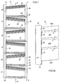
- a process chamber, or tower, is shown generally at 10 in Fig. 1, including a tray-type packing system according to the present invention, indicated generally at 12.
- An outer wall 14 confines the packing system 12, and may be provided by the packing system itself, or may be the actual wall of the process chamber into which the packing system is fitted. In either case, the wall 14 partially defines flow passages as part of the packing system 12, as discussed below.
- the process chamber 10 is used in processes wherein a gas and a liquid may interact when placed in mutual contact as a result of countercurrent flow of the two fluids through the chamber.
- Gas is introduced into the bottom of the chamber 10 as indicated by arrow A, and passes upwardly in the tower.
- Gas emerges from the top of the chamber 10, as indicated by the arrow B.
- Liquid is introduced into the top of the chamber 10 as indicated by the arrow C, and generally moves downwardly through the chamber, opposite to the upward movement of the gas. Liquid emerges from the bottom of the chamber as indicated by the arrow D.
- gas and liquid are brought into mutual contact and interact according to the process dictated by the natures of the gas and the liquid, and the conditions within the chamber. Consequently, the gas emerging at arrow B may be expected to be changed compared to the gas entering the chamber 10 at arrow A, and the liquid emerging at arrow D may be expected to be different from the liquid entering the chamber at arrow C.
- the packing system 12 causes the gas and the liquid to mutually contact within the chamber in co-current flow.
- the co-current flow of the gas and the liquid is achieved in stages that make up the packing system 12.
- a packing system according to the present invention may comprise any number of stages, including just one stage, the packing system 12 is shown to include six stages, 16, 17, 18, 19, 20 and 21, arranged in a single column so that all of the gas flow and all of the liquid flow passes through all of the stages.
- the stages 16-21 are identical except that the even numbered stages face toward one side and the odd numbered stages face toward the opposite side as illustrated.
- stages 16-21 are stacked so that, from top to bottom, for example, the orientation of the stages alternates.
- An end view of stages 18 and 19 is presented in Fig. 2, although the view of Fig. 2 would be the same for any even numbered stage above an odd numbered stage, for example.
- Each stage 16-21 includes a liquid distributor 22 and a gas-liquid separator 24, positioned above the distributor.
- the distributor 22 spreads liquid laterally across the packing stage. Gas flows upwardly through the distributor 22, which allows liquid to contact the gas and be picked up in the flow of the gas.
- the gas-liquid combination flows into the separator 24 wherein liquid is captured and collected while gas continues to flow upwardly out of the separator.
- the gas and liquid thus interact in generally upward co-current flow within the packing stage between the time the gas moves through the distributor and first contacts the liquid there, and the time the liquid is collected in the separator and the gas leaves the separator.
- Each distributor 22 includes multiple conduits 26 arranged in parallel, and mutually spaced apart, laterally across the packing stage. Liquid is received through an open end of each conduit 26 and extends along the conduit, generally toward the opposite, closed end thereof.
- the distributor conduits 26 of all of the even numbered packing sections 16, 18 and 20 are open to the right as viewed in Fig. 1, and the conduits of the odd numbered sections 17, 19 and 21 are open to the left.
- the conduits 26 are covered, and ports, or weirs, 28 are provided along each conduit for egress of the liquid.
- Each separator 24 includes multiple channels 30 arrayed in vertically-spaced layers, with each layer including a plurality of laterally-spaced channels.
- the channels 30 are U-shaped in cross section, so that they are open on top to receive liquid. As shown in Fig. 1, the channels 30 are sloped across the respective packing section so that liquid collected in the channels will flow toward the lower, open end of the channel in each case. The higher end of each channel is closed.
- separator channels 30 of all of the even numbered packing sections 16, 18 and 20 are open to the left as viewed in Fig. 1, and the channels of the odd numbered sections 17, 19 and 21 are open to the right.
- the conduits 26 and the channels 30 are connected at their ends to inner walls 32 and 34, which include appropriate holes to receive the ends of the conduits and channels.
- Fig. 2 shows a portion of a wall 34 included in the two stages 18 and 19, for example. Comparison between Figs 1 and 2 reveals that the ends of the channels 30 received by the wall 34 in section 18 are the lower, open ends of these channels, and the ends of the channels received by the same wall in section 19 are the higher, closed ends of those channels. Similarly, the ends of the distributor conduits 26 received by the wall 34 in the packing section 18 are closed, while the ends of the conduits received by the same wall in the section 19 are open.
- a flow passage is provided for transporting liquid to the open end of each conduit 26.
- the flow passages for all of the packing sections in Fig. 1 are provided by cooperation of the outer wall 14 and the inner wall 32 on the right of the chamber 10 as viewed in Fig. 1, and by cooperation of the outer wall 14 and the inner wall 34 on the left of the chamber.
- the flow passages, or downcomers, 36 thus formed also serve to transport liquid collected in the separators 24.
- the flow passage 36 leading to the open ends of the conduits 26 in the distributor of the highest packing stage 16 receives the liquid introduced into the packing system 12 at arrow C; the flow passage leading from the separator 24 of the lowest packing stage 21 communicates the liquid out of the packing system 12 at arrow D.
- Seals 38 are provided across the flow passages 36 at selected locations to direct the transport of liquid.
- a seals 38 are placed across the flow passages 36 just below the open right end of the distributor conduits 26 in the even numbered packing sections 16, 18 and 20, and just below the open left end of the distributor conduits in the odd numbered packing sections 17, 19 and 21
- the seals 38 are thus arranged to direct liquid collected in any separator 24 to a position below the distributor 22 immediately below the separator wherein the liquid was collected, that is, to a position below the packing section containing the separator wherein the liquid was collected.
- the liquid collected in a separator is transported to the open end of the conduits 26 of the distributor 22 in the packing section immediately below the packing section of the separator wherein the liquid was collected.
- Liquid collected in the separator 24 of the lowest packing section 21 is transported out of the packing system 12 at D. Also, liquid introduced into the packing system 12 at C is transported along a flow passage 36 to the open ends of the conduits 26 of the distributor 22 of the highest packing section 16.
- the channels 30 are arranged in each separator 24 in four layers, with the channels in each layer staggered laterally relative to the channels in the adjacent layer, or layers, so that there is no straight upward path through the separator.
- an array of deflection baffles 40 is positioned above the top layer of channels 30 in each separator 24.
- the baffles 40 are elongate strips that parallel the slope of the channels 30 and are mounted by connection to the two inner walls 32 and 34.
- Each strip baffle 40 is positioned centered over the opening between two adjacent channels 30 in the top layer of channels to deflect any gas-liquid combination that reaches the level of the baffle and facilitate the separation of liquid from the gas-liquid combination at the top layer of channels.
- the increase in pressure over the channels 30 due to the presence of the baffles 40 enhances liquid flow from the channels into the flow passage.
- a vent 42 is provided in the wall 32 or 34 above the deflection baffles 40 at the open ends of the channels 30 of each separator 24.
- the vents 42 relieve any pressure buildup in the flow passages 36 to insure that the pressure in the flow passages is lower than the pressure in the separators 24.
- an array of deflection baffles 44 is positioned above the array of conduits 26 in each distributor 22.
- the baffles 44 are elongate strips that parallel the conduits 26 and are mounted by connection to the two inner walls 32 and 34.
- Each strip baffle 44 is positioned centered over the opening between two adjacent conduits 26 in the respective distributor to deflect and produce turbulence in the gas and liquid combining at the distributor to enhance that combining process. It is preferred that the width of the deflector baffles 44 is approximately one-third greater than the lateral spacing between adjacent conduits 26.
- Multiple layers of parallel deflector baffles 44 may be positioned over each distributor 22, with the layers staggered so that a baffle is centered over a spacing between adjacent baffles in the next lower layer.
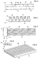
- Each conduit 26 is an elongate tube of generally rectangular cross section, having a recessed cover to form a shallow trough 46 on the top of the conduit.
- a dispersion ladder is provided within the conduit 26 by an array of flow regulators in the form of plates 48, extending downwardly from the inside of the cover of the conduit at spaced positions along the length of the conduit.
- a skirt, or partition, 50 extends downwardly from the top of the open end of the conduit 26 where the conduit is connected to the inner wall 34.
- liquid is transported down the flow passage 36 to the opened end of each conduit 26, and flows into the conduit under the skirt 50, which cooperates with the liquid to form a seal against gas of any kind flowing through the opening between the interior of the conduit and the flow passage.
- the dispersion plates 48 tend to slow the movement of liquid within the conduit 26 to enhance the even distribution of liquid along the length of the conduit, and exposure to the ports 28.
- gas rises between the conduits 26 in a distributor 22 liquid flows out of the conduits through the ports 28 to mix and interact with the gas.
- the narrow spacing between the conduits 26 causes the gas flowing therethrough to accelerate, thus insuring that the liquid is carried upwardly by the gas flow.
- the deflection baffles 44 tend to produce turbulence in the gas and gas-liquid combination flowing upwardly away from the conduits 26 to enhance the contact between liquid and the gas. A portion of the liquid collects in the recesses 46 for further liquid distribution and exposure to gas moving upwardly through the array of conduits 26. The result is an enhanced mixing and contacting of gas and liquid as the gas-liquid proceeds upwardly from the distributor 22.
- the distributor 52 includes multiple conduits 54 that feature one end open to receive liquid and the opposite end closed, with the conduits mounted between inner walls 32 and 34 of a packing section, just as in the case of the conduits 26 of Figs. 1 and 2.
- Each conduit 54 is an elongate tube with a cross section featuring a reduction in width in the upper portion of the conduit to form two external shoulders 56 extending the length of the conduit.
- a vertical side wall 58 extends above each shoulder 56, and an external wall 60 is positioned above each shoulder, displaced away from and facing the corresponding wall 58.
- each conduit 54 The ports, or weirs, 62 included in each conduit 54 are located in the walls 58, above the shoulders 56 and opposite the external walls 60 which thus face the ports.
- the ports 62 are wedge-shaped so that liquid tends to emerge from the conduit 54 at faster rates, for a given set of pressure conditions, when there is a larger amount of liquid in the conduit.
- a dispersion ladder is provided within each conduit 54 by an array of flow regulators in the form of plates 64, extending upwardly from the inside of the bottom of the conduit at spaced positions along the length of the conduit.
- a skirt, or partition, (not shown) extends downwardly from the top of the open end of each conduit 54 where the conduit is connected to the inner wall of the packing system
- liquid is transported to and flows into the conduits 54, with the dispersion plates 64 enhancing the even distribution of liquid along the length of each conduit, as in the case of the operation of the conduits 26 in Figs. 2 and 3, for example.
- liquid As gas rises through the spaces between the conduits 54 in a distributor 52, liquid is drawn out of the conduits through the ports 62 to mix and interact with the gas.
- Liquid that does not immediately mix with gas and move off with the gas collects on the shoulders 56, being deflected back toward the walls 58 by the external walls 60. The liquid thus collected on the shoulders 56 is continuously exposed to gas flowing upwardly between the conduits 54 for contact and interaction with the gas.
- FIG. 7-9 Yet another form of liquid distributor for use in a packing system according to the present invention is shown generally at 66 in Figs. 7-9.
- the distributor 66 includes multiple conduits 68 that feature one end open to receive liquid and the opposite end closed, with the conduits mounted between inner walls 32 and 34 of a packing section, just as in the case of the conduits 26 of Figs. 1, 2.
- Each conduit 68 is an elongate tube with a generally rectangular cross section, having a recessed cover to form a shallow trough 70 on the top of the conduit.
- the ports, or weirs, 72 included in each conduit 68 are located in the cover of the conduit, within the recess 70.
- a dispersion ladder (not shown) may be provided within each conduit 68 in the form of downwardly extending plates 48, as in Figs. 3 and 4, or upwardly extending plates 64, as in Figs. 5 and 6, to enhance the even distribution of liquid along the conduits as discussed above.
- a skirt, or partition, (not shown) extends downwardly from the top of the open end of each conduit 68 where the conduit is connected to the inner wall of the packing system.
- an array of deflection baffles 74 is positioned above the array of conduits 68 in the distributor 66.
- the baffles 74 are elongate strips that parallel the conduits 68 and are mounted by connection to the two inner walls 32 and 34 of the packing system as shown in Figs. 1 and 2, for example.
- Each strip baffle 44 is positioned centered over the opening between two adjacent conduits 68 to deflect and produce turbulence in the gas and liquid combining at the distributor to enhance that combining process, as discussed above in relation to the baffles 44 in Figs. 1-4.
- liquid is transported to and flows into the conduits 68, with dispersion plates (not shown) enhancing the even distribution of liquid along the length of each conduit, as in the case of the operation of the conduits 26 and 54 discussed above.
- dispersion plates not shown
- Liquid that does not immediately mix with gas is collected in the recesses 70 where the liquid is continuously exposed to gas flowing upwardly between the conduits 68 for contact and interaction with the gas.
- the deflection baffles 74 tend to produce turbulence in the gas and gas-liquid combination flowing upwardly away from the conduits 68 to enhance the contact between vapor of the liquid and the gas. The result is an enhanced mixing and contacting of gas and liquid as the gas-liquid proceeds upwardly from the distributor 66.
- the array of conduits 68 used to form a distributor 66 may be provided in modular form for ease of construction, such as on a palette 76. In practice, any of the distributors discussed herein may be so constructed.
- the ends of the conduits 68 extend beyond the ends of the palette 76 so that the conduit ends may be received within appropriate holes in the inner walls 32 and 34 for ease of mounting of the conduits.
- the accompanying extension of the conduits ends into the packing system inner walls 32 and 34 is shown in Figs, 1, 3 and 7, for example.
- any of the different types of distributor conduits discussed above may employ either of the different types of dispersion ladders discussed.
- dispersion plates located near the level of the ports in the conduits achieve better results.
- a preferred dispersion plate location is illustrated in Fig. 3 where the ports 28 and the dispersion plates 48 are both located at a similar level near the top of the conduit 26.
- the ports 72 are in the cover of the conduit 68
- the high dispersion plate 48 location of Fig. 3 would be selected.
- the ports 28 of Fig. 3 were located near the bottom of the conduit 26, the low dispersion plate 64 location of Figs. 5 and 6 would be preferred.
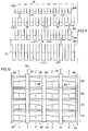
- the separator 24 includes four layers of channels 30a, 30b, 30c and 30d, although any number of layers of channel may be used in such a separator.
- the channels 30a-30c are generally rectangular, with the width E of all the channels being the same. Also, the spacing F between adjacent channels is the same for all cases. However, while the depth of all of the channels in a given layer is the same, the depth of the channels is greater than the depth of the channels in each higher layer in the separator 24. Additionally, the vertical spacing S between adjacent layers of channels may be the same for all layers.
- a skirt extends downwardly from the top of the open end of each channel where the channel is connected to the inner wall such as 34 in a packing system to cooperate with the level of liquid in the channel in providing a seal to prevent gas flow into the flow passage 36.
- the channels also extend into the inner wall 32 or 34 for mounting in the packing system, as is shown in Fig. 10.
- the deflector baffles 40 are a distance G wide.
- a gas-liquid combination rises from a distributor (not shown) below the separator 24, and accelerates as it passes between the channels. At the same time the fluid combination also impinges on the bottom of the channels 30a-30d as well as the deflector baffles 40 to swirl around the channels.
- the fluid combination thus traversing the separator 24 liquid comes out of the combination and is collected in the open-top channels 30a-30d, the gas continuing on upwardly.
- the collected liquid flows down the slopped channels 30a-30d toward the open ends thereof to be deposited in the flow passage 36.
- the lowest channel 30a collects the most liquid since it is exposed to the fluid combination first, before any liquid is removed. Each succeeding higher channel is exposed to a fluid combination with less liquid content than the lower channels, and therefore collects a lesser amount of liquid.
- the depths, and therefore the capacity, of the channels 30a-30d decreases going higher in the separator 24.
- the length of the skirts at the open ends of the channels varies depending on the depth of the channels. As shown in Fig. 10, the lowest channel 30a is the deepest, with the longest extending skirt 78, the next higher channel 30b is less deep with a shorter skirt 80, then next higher channel 30c is even less deep with an even shorted skirt 82, and the highest channel 30d is the shallowest, with the shortest skirt 84.
- the spacing between the lower edge of each skirt 78-84 and the bottom of the respective channel 30a-30d also decreases, going from the lowest channel 30a to the highest channel 30d to accommodate the deeper body of liquid to be collected in the lower channels.
- the skirts 78-84 are indicated on one channel in each layer in Fig. 11.
- the capability for a separator 24 to remove liquid from the gas-liquid combination passing upwardly through the separator is progressively enhanced with reduction of the channel width E while maintaining the spacing F at approximately 75% of E, and maintaining the vertical spacing S at approximately 117% of E.
- the dimension E should be no greater than 1.5 centimeters, and should be as low as 0.75 centimeters or less where very high separator performance is needed.
- the baffle width G is maintained at approximately the same value as E.
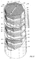
- a process tower is shown generally at 86 in Fig. 12, including a packing system according to the present invention, shown generally at 88, that is constructed in modular form.
- the tower 86 encloses the packing system 88 in an outer, cylindrical wall 90.
- the packing system 88 includes twelve packing sections arranged in two columns, with sections shown generally at 92, 94, 96, 98, 100 and 102 stacked in one column, and sections shown generally at 104, 106, 108, 110, 112 and 114 stacked in a second column, with all sections shaped generally with beveled ends to fit within the cylindrical tower wall 90.
- Each packing section 92-102 in one column features inner walls 116 and 118 having extended side edges that seal with the outer wall 90.
- Each packing section 104-114 in the other column features inner walls 120 and 122 having extended side edges that seal with the outer wall 90 as well.
- Inner, side walls 124 and 126 extend between inner walls 116 and 118, and between inner walls 120 and 122, respectively.
- a vertical, interior wall 127 separates the two columns of sections 92-102 and 104-114.
- Seals in the form of shelf members 128 are provided to seal the inner walls 116-122 to the outer wall 90 just below the open ends of the conduits in liquid distributors of the packing sections 92-114.
- flow passages are formed between the outer wall 90 and the inner walls 116-122 to transport liquid collected in separators to locations below the distributors of the packing sections containing the respective separators wherein the liquid was collected.
- packing section 104 includes a liquid distributor shown generally at 130, including an array of conduits 132 and a layer of deflection baffles 134 above the conduits.
- the conduits 132 may be of any type described above.
- the closed ends of the conduits 132 are visible in Fig. 12.
- a separator 136 is located above the distributor 130 in the section 104, and includes four layers of channels 138 and a layer of deflection baffles 140 above the channels.
- a vent 142 is located above the baffles 140.
- the lower, open ends of the channels 138 are visible in Fig. 12. Liquid enters the tower 86 by way of the flow passage leading down to the first seal 128 and the open ends of the distributor conduits 132 in the section 104 (not visible) at the arrow H.
- Gas rising through the distributor 146 of the section 106 interacts with liquid emerging from the conduits 144 of that distributor, and the resulting gas-liquid combination rises to channels 148 in a separator 150 of the same section. Liquid collected in the channels 148 flows out of the open ends of those channels (toward the back in Fig. 12) into the flow passage formed between the outer wall 90 and the inner wall 120, down to a seal 128 where the liquid enters the open ends of distributor conduits in the next section 108.
- the distributor 146 and the separator 150 of section 106 also include arrays of deflector baffles 152 and 154, respectively, and a vent is located above the separator (not visible).
- the packing sections 108 and 112 are identical to the packing section 104, and the packing sections 110 and 114 are identical to the section 106. Also, the packing sections 92, 96 and 100 are mirror images of the packing sections 104, 108 and 112, while the sections 94, 98 and 102 are mirror images of the sections 106, 110 and 114.
- the system 156 includes four columns 158, 160, 162 and 164 of packing sections, with each column containing four packing sections 166, 168 170 and 172 for a total of sixteen packing sections.
- Liquid enters the system 156 through the tops of two stacks of flow passages 174 and 176 at arrows J and K, respectively.
- Gas enters the system through the bottoms of the four columns 158, 160, 162 and 164 at arrows O, P, Q and R, respectively, and leaves through the tops of the columns at arrows S, T, U and v, respectively.
- Each packing section may be of any type described herein, and includes a separator 178 and a distributor 180.
- a central stack of flow passages and two peripheral stacks of flow passages are also provided.
- Flow passage seals 188 are positioned in the flow passages 174, 176, 182, 184 and 186 at positions just below the open ends of distributor conduits.
- the packing sections 166-172 operate as described above in relation to the apparatus shown in Figs. 1-11, with liquid collected in the separator of one section being transported down to the separator of the next lower section. However, the liquid passing downwardly within the stacked central flow passage 182 will pass between columns 160 and 162, in going from a section 166 and a section 168, or between a section 170 and a section 172.
- liquid passing downwardly within the stacked flow passage 174 will pass between columns 158 and 160 in going from a section 168 to a section 170
- liquid passing downwardly within the stacked flow passage 176 will pass between columns 162 and 164 in going from a section 168 to a section 170.
Landscapes
- Chemical & Material Sciences (AREA)
- Chemical Kinetics & Catalysis (AREA)
- Physics & Mathematics (AREA)
- Thermal Sciences (AREA)
- Engineering & Computer Science (AREA)
- Organic Chemistry (AREA)
- Mechanical Engineering (AREA)
- General Engineering & Computer Science (AREA)
- Physical Or Chemical Processes And Apparatus (AREA)
- Vaporization, Distillation, Condensation, Sublimation, And Cold Traps (AREA)
- Feeding, Discharge, Calcimining, Fusing, And Gas-Generation Devices (AREA)
Applications Claiming Priority (2)
| Application Number | Priority Date | Filing Date | Title |
|---|---|---|---|
| US08/555,889 US5695548A (en) | 1995-11-13 | 1995-11-13 | Method and apparatus for producing co-current fluid contact |
| US555889 | 1995-11-13 |
Publications (1)
| Publication Number | Publication Date |
|---|---|
| EP0773050A1 true EP0773050A1 (en) | 1997-05-14 |
Family
ID=24218993
Family Applications (1)
| Application Number | Title | Priority Date | Filing Date |
|---|---|---|---|
| EP96308213A Withdrawn EP0773050A1 (en) | 1995-11-13 | 1996-11-13 | Method and apparatus for producing co-current fluid contact |
Country Status (5)
| Country | Link |
|---|---|
| US (1) | US5695548A (enExample) |
| EP (1) | EP0773050A1 (enExample) |
| JP (1) | JPH1015301A (enExample) |
| CN (1) | CN1158407A (enExample) |
| CA (1) | CA2189607A1 (enExample) |
Cited By (4)
| Publication number | Priority date | Publication date | Assignee | Title |
|---|---|---|---|---|
| WO2010077405A1 (en) * | 2008-12-31 | 2010-07-08 | Uop Llc | Improved liquid distribution in co-current contacting apparatuses |
| WO2010077406A1 (en) * | 2008-12-31 | 2010-07-08 | Uop Llc | Improved vapor-liquid contacting in co-current contacting apparatuses |
| US9283516B2 (en) | 2010-11-24 | 2016-03-15 | Doosan Babcock Limited | Column structure for an absorption column |
| US9346009B2 (en) | 2010-11-24 | 2016-05-24 | Doosan Babcock Limited | Structure of an absorption column |
Families Citing this family (15)
| Publication number | Priority date | Publication date | Assignee | Title |
|---|---|---|---|---|
| EP1330297A1 (en) * | 2000-10-23 | 2003-07-30 | Shell Internationale Researchmaatschappij B.V. | Column for counter-currently contacting vapour and liquid |
| WO2002074404A1 (en) * | 2001-03-19 | 2002-09-26 | Shell Internationale Research Maatschappij B.V. | Gas-liquid separator |
| US7137622B2 (en) * | 2004-04-22 | 2006-11-21 | Exxonmobil Research And Engineering Company | De-entrainment of liquid particles from gas |
| US7267330B1 (en) | 2005-07-06 | 2007-09-11 | Jaeger Products, Inc. | Split ring seal |
| CN102202766A (zh) | 2008-08-21 | 2011-09-28 | 碳工程合伙有限公司 | 二氧化碳捕获方法和设施 |
| CN105102402B (zh) * | 2013-04-18 | 2019-06-18 | 霍尼韦尔国际公司 | 生产氟化有机物的反应体系和方法 |
| EP2826532A1 (en) * | 2013-07-18 | 2015-01-21 | Sulzer Chemtech AG | A liquid mixing collector and a method for its use |
| FR3012658B1 (fr) * | 2013-10-24 | 2016-01-01 | Areva Np | Procede de reparation des pions de centrage d'assemblages de combustible nucleaire |
| US10421039B2 (en) | 2016-06-14 | 2019-09-24 | Carbon Engineering Ltd. | Capturing carbon dioxide |
| RU2631701C1 (ru) * | 2016-08-22 | 2017-09-26 | Федеральное государственное бюджетное учреждение науки Институт теплофизики им. С.С. Кутателадзе Сибирского отделения Российской академии наук (ИТ СО РАН) | Противоточная колонна с динамически управляемым распределителем жидкости |
| WO2018152049A1 (en) * | 2017-02-14 | 2018-08-23 | Lantec Products, Inc | Bioremediation and mass-transfer using polyolefin packing |
| CN106871499B (zh) * | 2017-02-23 | 2019-10-25 | 江苏利尔机车科技有限公司 | 一种结构灵活且易于拆装清洗的翅片式冷凝器 |
| JP7015850B2 (ja) * | 2017-06-15 | 2022-02-03 | エクソンモービル アップストリーム リサーチ カンパニー | コンパクト並流接触システムを使用する分別システム |
| US12239936B2 (en) | 2018-04-17 | 2025-03-04 | Carbon Engineering Ulc | Hydration of gas streams |
| CN111424063B (zh) * | 2020-04-07 | 2024-08-02 | 河北广玉淀粉糖业有限公司 | 淀粉液化生产工艺及其生产系统 |
Citations (4)
| Publication number | Priority date | Publication date | Assignee | Title |
|---|---|---|---|---|
| GB448556A (en) * | 1934-11-10 | 1936-06-10 | Arthur Joseph Victor Underwood | Improvements in or relating to a method of and means for fractional distillation and like operations |
| DE2904143A1 (de) * | 1979-02-03 | 1981-01-08 | Leipzig Chemieanlagen | Gas(dampf)-fluessigkeitskontakteinrichtung fuer stoff- und waermeuebertragung im phasengleich- oder im phasengegenstrom |
| US4361469A (en) | 1981-02-17 | 1982-11-30 | Trutna William R | Process for using cocurrent contacting distillation columns |
| DE4301712A1 (de) * | 1993-01-22 | 1994-07-28 | Linde Ag | Anlage und Verfahren zur Tieftemperaturzerlegung von Luft und Flüssigkeitsverteiler für eine Stoffaustauschsäule |
Family Cites Families (18)
| Publication number | Priority date | Publication date | Assignee | Title |
|---|---|---|---|---|
| US668866A (en) * | 1900-06-07 | 1901-02-26 | Charles A Young | Exhaust-head for steam-pipes. |
| US801211A (en) * | 1903-12-11 | 1905-10-10 | Wilhelm Buetzow | Oil-separator. |
| US981058A (en) * | 1910-09-12 | 1911-01-10 | Otto Buehring | Apparatus for the separation of liquids from gases or vapors. |
| US1764190A (en) * | 1924-08-27 | 1930-06-17 | Foster Wheeler Corp | Oil-vapor separation and condensation |
| US1655998A (en) * | 1925-04-23 | 1928-01-10 | Forrest E Gilmore | Counter flow still |
| US1974768A (en) * | 1932-05-02 | 1934-09-25 | Riley Stoker Corp | Gas scrubber |
| US2197189A (en) * | 1938-10-04 | 1940-04-16 | James A Morgan | Scrubber |
| US2646266A (en) * | 1948-03-22 | 1953-07-21 | Braun & Co C F | Multiple flow column |
| NL136761C (enExample) * | 1961-03-03 | |||
| US3343821A (en) * | 1964-02-05 | 1967-09-26 | Fritz W Glitsch & Sons Inc | Grids for vapor-liquid contact apparatus |
| US3445094A (en) * | 1964-06-08 | 1969-05-20 | Phillips Petroleum Co | Dynamically balanced multi-path liquid-gas contacting |
| US3722839A (en) * | 1970-07-20 | 1973-03-27 | Merix Corp | Vapor liquid contacting |
| US3803997A (en) * | 1972-01-21 | 1974-04-16 | Mahon Ind Corp | Particle collecting device |
| SU762906A1 (ru) * | 1974-12-17 | 1980-09-15 | Mo I Khim Mash | Контактное устройство для тепломассообменных аппаратов 1 |
| US4776989A (en) * | 1983-09-19 | 1988-10-11 | The Dow Chemical Company | Method and apparatus for liquid feed to liqiud distributors in fluid-liquid contacting towers |
| US4762651A (en) * | 1987-05-26 | 1988-08-09 | Uni-Frac, Inc. | Vapor/liquid contact device |
| US4909967A (en) * | 1988-11-03 | 1990-03-20 | Glitsch, Inc. | Liquid distributor assembly for packed tower |
| US5051214A (en) * | 1989-01-13 | 1991-09-24 | Glitsch, Inc. | Double-deck distributor and method of liquid distribution |
-
1995
- 1995-11-13 US US08/555,889 patent/US5695548A/en not_active Expired - Lifetime
-
1996
- 1996-11-05 CA CA002189607A patent/CA2189607A1/en not_active Abandoned
- 1996-11-13 EP EP96308213A patent/EP0773050A1/en not_active Withdrawn
- 1996-11-13 CN CN96120594A patent/CN1158407A/zh active Pending
- 1996-11-13 JP JP8315670A patent/JPH1015301A/ja active Pending
Patent Citations (4)
| Publication number | Priority date | Publication date | Assignee | Title |
|---|---|---|---|---|
| GB448556A (en) * | 1934-11-10 | 1936-06-10 | Arthur Joseph Victor Underwood | Improvements in or relating to a method of and means for fractional distillation and like operations |
| DE2904143A1 (de) * | 1979-02-03 | 1981-01-08 | Leipzig Chemieanlagen | Gas(dampf)-fluessigkeitskontakteinrichtung fuer stoff- und waermeuebertragung im phasengleich- oder im phasengegenstrom |
| US4361469A (en) | 1981-02-17 | 1982-11-30 | Trutna William R | Process for using cocurrent contacting distillation columns |
| DE4301712A1 (de) * | 1993-01-22 | 1994-07-28 | Linde Ag | Anlage und Verfahren zur Tieftemperaturzerlegung von Luft und Flüssigkeitsverteiler für eine Stoffaustauschsäule |
Cited By (5)
| Publication number | Priority date | Publication date | Assignee | Title |
|---|---|---|---|---|
| WO2010077405A1 (en) * | 2008-12-31 | 2010-07-08 | Uop Llc | Improved liquid distribution in co-current contacting apparatuses |
| WO2010077406A1 (en) * | 2008-12-31 | 2010-07-08 | Uop Llc | Improved vapor-liquid contacting in co-current contacting apparatuses |
| US8052126B2 (en) | 2008-12-31 | 2011-11-08 | Uop Llc | Liquid distribution in co-current contacting apparatuses |
| US9283516B2 (en) | 2010-11-24 | 2016-03-15 | Doosan Babcock Limited | Column structure for an absorption column |
| US9346009B2 (en) | 2010-11-24 | 2016-05-24 | Doosan Babcock Limited | Structure of an absorption column |
Also Published As
| Publication number | Publication date |
|---|---|
| CN1158407A (zh) | 1997-09-03 |
| CA2189607A1 (en) | 1997-05-14 |
| JPH1015301A (ja) | 1998-01-20 |
| US5695548A (en) | 1997-12-09 |
Similar Documents
| Publication | Publication Date | Title |
|---|---|---|
| US5695548A (en) | Method and apparatus for producing co-current fluid contact | |
| AU737526B2 (en) | Co-current contacting separation tray design and methods for using same | |
| US6682633B1 (en) | Apparatus for cocurrent fractional distillation | |
| EP0757583B1 (en) | Vapor-liquid contact tray and downcomer assembly and method employing same | |
| US7137622B2 (en) | De-entrainment of liquid particles from gas | |
| US7004988B2 (en) | Gas-liquid separator | |
| KR20010012453A (ko) | 2단 하강유로를 구비한 기액 접촉 트레이 | |
| EP2414090B1 (en) | Improved fluid distribution to parallel flow vapor-liquid contacting trays | |
| KR101603367B1 (ko) | 병류 접촉 장치 내 액체 분배 개선 | |
| US6830607B2 (en) | Slurry tray and slurry tray assembly for use in fractionation towers | |
| US4818346A (en) | Vertical distillation column with a de-entrainment device | |
| US5683493A (en) | Packing for separation columns and process of use | |
| JPS60257802A (ja) | 気液接触塔 | |
| US10989471B2 (en) | Multiple pass, parallel flow downcomer tray for a mass transfer column | |
| EP3995195A1 (en) | A multistage liquid distributor for a separation device comprising a dual-trough pre-distributor |
Legal Events
| Date | Code | Title | Description |
|---|---|---|---|
| PUAI | Public reference made under article 153(3) epc to a published international application that has entered the european phase |
Free format text: ORIGINAL CODE: 0009012 |
|
| AK | Designated contracting states |
Kind code of ref document: A1 Designated state(s): AT BE CH DE DK ES FI FR GB GR IE IT LI LU MC NL PT SE |
|
| 17P | Request for examination filed |
Effective date: 19971015 |
|
| 17Q | First examination report despatched |
Effective date: 19990622 |
|
| APAB | Appeal dossier modified |
Free format text: ORIGINAL CODE: EPIDOS NOAPE |
|
| APAB | Appeal dossier modified |
Free format text: ORIGINAL CODE: EPIDOS NOAPE |
|
| APAD | Appeal reference recorded |
Free format text: ORIGINAL CODE: EPIDOS REFNE |
|
| APBT | Appeal procedure closed |
Free format text: ORIGINAL CODE: EPIDOSNNOA9E |
|
| STAA | Information on the status of an ep patent application or granted ep patent |
Free format text: STATUS: THE APPLICATION HAS BEEN WITHDRAWN |
|
| 18W | Application withdrawn |
Effective date: 20050412 |
|
| APAF | Appeal reference modified |
Free format text: ORIGINAL CODE: EPIDOSCREFNE |