EP0772736B1 - Dynamic electronic control system for controlling the injection pressure of a rail injection system - Google Patents
Dynamic electronic control system for controlling the injection pressure of a rail injection system Download PDFInfo
- Publication number
- EP0772736B1 EP0772736B1 EP95926481A EP95926481A EP0772736B1 EP 0772736 B1 EP0772736 B1 EP 0772736B1 EP 95926481 A EP95926481 A EP 95926481A EP 95926481 A EP95926481 A EP 95926481A EP 0772736 B1 EP0772736 B1 EP 0772736B1
- Authority
- EP
- European Patent Office
- Prior art keywords
- pressure
- rail
- regulator
- fuel
- signal
- Prior art date
- Legal status (The legal status is an assumption and is not a legal conclusion. Google has not performed a legal analysis and makes no representation as to the accuracy of the status listed.)
- Expired - Lifetime
Links
Images

Classifications
-
- F—MECHANICAL ENGINEERING; LIGHTING; HEATING; WEAPONS; BLASTING
- F02—COMBUSTION ENGINES; HOT-GAS OR COMBUSTION-PRODUCT ENGINE PLANTS
- F02D—CONTROLLING COMBUSTION ENGINES
- F02D41/00—Electrical control of supply of combustible mixture or its constituents
- F02D41/30—Controlling fuel injection
- F02D41/38—Controlling fuel injection of the high pressure type
- F02D41/3809—Common rail control systems
- F02D41/3836—Controlling the fuel pressure
- F02D41/3863—Controlling the fuel pressure by controlling the flow out of the common rail, e.g. using pressure relief valves
-
- F—MECHANICAL ENGINEERING; LIGHTING; HEATING; WEAPONS; BLASTING
- F02—COMBUSTION ENGINES; HOT-GAS OR COMBUSTION-PRODUCT ENGINE PLANTS
- F02D—CONTROLLING COMBUSTION ENGINES
- F02D41/00—Electrical control of supply of combustible mixture or its constituents
- F02D41/02—Circuit arrangements for generating control signals
- F02D41/14—Introducing closed-loop corrections
- F02D41/1401—Introducing closed-loop corrections characterised by the control or regulation method
-
- F—MECHANICAL ENGINEERING; LIGHTING; HEATING; WEAPONS; BLASTING
- F02—COMBUSTION ENGINES; HOT-GAS OR COMBUSTION-PRODUCT ENGINE PLANTS
- F02D—CONTROLLING COMBUSTION ENGINES
- F02D41/00—Electrical control of supply of combustible mixture or its constituents
- F02D41/02—Circuit arrangements for generating control signals
- F02D41/14—Introducing closed-loop corrections
- F02D41/1401—Introducing closed-loop corrections characterised by the control or regulation method
- F02D2041/1413—Controller structures or design
- F02D2041/1415—Controller structures or design using a state feedback or a state space representation
-
- F—MECHANICAL ENGINEERING; LIGHTING; HEATING; WEAPONS; BLASTING
- F02—COMBUSTION ENGINES; HOT-GAS OR COMBUSTION-PRODUCT ENGINE PLANTS
- F02D—CONTROLLING COMBUSTION ENGINES
- F02D41/00—Electrical control of supply of combustible mixture or its constituents
- F02D41/02—Circuit arrangements for generating control signals
- F02D41/14—Introducing closed-loop corrections
- F02D41/1401—Introducing closed-loop corrections characterised by the control or regulation method
- F02D2041/1413—Controller structures or design
- F02D2041/1426—Controller structures or design taking into account control stability
-
- F—MECHANICAL ENGINEERING; LIGHTING; HEATING; WEAPONS; BLASTING
- F02—COMBUSTION ENGINES; HOT-GAS OR COMBUSTION-PRODUCT ENGINE PLANTS
- F02D—CONTROLLING COMBUSTION ENGINES
- F02D41/00—Electrical control of supply of combustible mixture or its constituents
- F02D41/02—Circuit arrangements for generating control signals
- F02D41/14—Introducing closed-loop corrections
- F02D41/1401—Introducing closed-loop corrections characterised by the control or regulation method
- F02D2041/1433—Introducing closed-loop corrections characterised by the control or regulation method using a model or simulation of the system
-
- F—MECHANICAL ENGINEERING; LIGHTING; HEATING; WEAPONS; BLASTING
- F02—COMBUSTION ENGINES; HOT-GAS OR COMBUSTION-PRODUCT ENGINE PLANTS
- F02D—CONTROLLING COMBUSTION ENGINES
- F02D2200/00—Input parameters for engine control
- F02D2200/02—Input parameters for engine control the parameters being related to the engine
- F02D2200/06—Fuel or fuel supply system parameters
- F02D2200/0602—Fuel pressure
-
- F—MECHANICAL ENGINEERING; LIGHTING; HEATING; WEAPONS; BLASTING
- F02—COMBUSTION ENGINES; HOT-GAS OR COMBUSTION-PRODUCT ENGINE PLANTS
- F02D—CONTROLLING COMBUSTION ENGINES
- F02D2250/00—Engine control related to specific problems or objectives
- F02D2250/31—Control of the fuel pressure
Definitions
- the present invention relates to a dynamic electronic control system for controlling the injection pressure of a rail injection system.
- Control systems which provide for controlling the injection pressure of fuel supply systems wherein a pump supplies the fuel at high pressure (1000-1300 bar) to a rail presenting a number of outlets communicating with respective injectors.
- Such supply systems also comprise a pressure regulator interposed between the pump outlet and the rail inlet, and communicating with a fuel return conduit.
- Known control systems comprise an electronic control unit supplied with a first signal generated by a pressure sensor on the rail, and a second signal representing an optimum reference pressure, and which processes the input signals to generate a pressure regulator drive signal.
- Injection pressure control systems of the above type provide for only approximate control, which is ineffective under certain operating conditions of the fuel supply system.
- a dynamic control system for controlling the injection pressure of an internal combustion engine fuel injection system
- Number 1 in Figure 1 indicates a dynamic electronic injection pressure control system applied to the injection system 4 of an internal combustion engine 6 (shown schematically), in particular a diesel engine.
- Injection system 4 comprises an electric supply pump 8, the inlet of which is connected by a supply conduit 10 to a fuel tank 12, and the outlet 8a of which is connected by a high-pressure (1000-1300 bar) supply line 15 to the inlet 17a of a known rail 17.
- a high-pressure (1000-1300 bar) supply line 15 to the inlet 17a of a known rail 17.
- Rail 17 presents a number of outlets 19a, 19b, 19c, 19d communicating with respective injectors 21a, 21b, 21c, 21d of engine 6 (common rail).
- Injection system 4 also comprises a pressure regulator 24 located along high-pressure line 15 and preferably consisting of a two-way solenoid valve controlled by an electronic control unit 27. More specifically, solenoid valve 24 comprises an electric winding 30 (shown schematically) for axially displacing a shutter 26 (also shown schematically).
- Pressure regulator 24 also communicates with a first fuel return conduit (bypass) 28 terminating in tank 12.
- Injection system 4 also comprises a second fuel return conduit 29 presenting inlets communicating with recirculating outlets of injectors 21a-21d, and an outlet 29a connected to tank 12.
- Electronic control unit 27 is supplied by an electric battery 34 which also supplies the various electric devices (not shown) cooperating with engine 6.
- Control unit 27 is supplied with a number of information signals N detected on the engine (e.g. relative to engine speed, pressure in the intake manifold (not shown), position of the accelerator (not shown), etc.), and generates a number of control signals Tj for controlling injectors 21a-21d after being decoded and amplified by a power circuit 32.
- control unit 27 is supplied with a first pressure signal Pmis generated by a pressure sensor 38 on rail 17, and with a second signal Prif representing an optimum reference pressure, e.g. obtained from an electronic table (not shown) or entered manually.
- Control unit 27 comprises an adding node 40 presenting an adding input (+) and a subtracting input (-) supplied respectively with signals Prif and Pmis digitized by A/D sampling units 42a, 42b (shown schematically).
- Adding node 40 presents an output 40u by which a digital error signal Err(z) is supplied to the input 50a of a regulating circuit 50 which also presents an output 50b generating a digital signal U(z) for driving solenoid valve 24, and communicating over electric line 51 with a control circuit (not shown) of solenoid valve 24.
- coefficient Kc 1 K t S nozzle ⁇ V batt R L ⁇ 2 ⁇ fc T
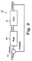
- Injection system 4 and control system 1 form a feedback system 90 (Figure 2) which may be represented schematically by a first block 100 defining the transfer function R(z) of regulator 50, and a second block 110 input-connected to the output of first block 100 and representing the physical input-output system described by transfer function G(z).
- Figure 2 may be represented schematically by a first block 100 defining the transfer function R(z) of regulator 50, and a second block 110 input-connected to the output of first block 100 and representing the physical input-output system described by transfer function G(z).
- the first block 100 also presents an input communicating with an adding node 120 supplied with the reference pressure signal Prif(z) and the feedback signal Pmis(z) from the output of block 110.
- Overshoot s is defined as the maximum amount by which system response deviates from the steady-state value (see A.ISIDORI, Control Systems, SIDEREA, ROME 1979, p. 114).
- Equation (7) permits the passband Bp of the system in the closed-loop configuration to be obtained after establishing rise time Ts.
- the gain of regulator circuit 50 also presents an upper limit Kcmax which is defined according to the extent to which system 90 is effected by noise. More specifically, the upper limit Kcmax defined is that above which interference in the output quantity (Pmis(z)) results in impaired stability of the system.
- the system described features a regulator 50 implementing a transfer function R(z) calculated by means of a model of the physical system (block 110) simulating performance of the injection system, so that system 1 provides for faithfully reproducing the control specifications.
- System 1 also presents a wide margin of stability and a wide passband.
- system 1 The stability of system 1 is full-range, i.e. system 1 remains stable regardless of variations in the parameters of the physical system.
Landscapes
- Engineering & Computer Science (AREA)
- Chemical & Material Sciences (AREA)
- Combustion & Propulsion (AREA)
- Mechanical Engineering (AREA)
- General Engineering & Computer Science (AREA)
- Electrical Control Of Air Or Fuel Supplied To Internal-Combustion Engine (AREA)
- Fuel-Injection Apparatus (AREA)
Applications Claiming Priority (3)
| Application Number | Priority Date | Filing Date | Title |
|---|---|---|---|
| IT94TO000609A IT1266892B1 (it) | 1994-07-22 | 1994-07-22 | Sistema elettronico di controllo dinamico della pressione di iniezione in un impianto di iniezione a collettore comune. |
| ITTO940609 | 1994-07-22 | ||
| PCT/IT1995/000121 WO1996003577A1 (en) | 1994-07-22 | 1995-07-21 | Dynamic electronic control system for controlling the injection pressure of a rail injection system |
Publications (2)
| Publication Number | Publication Date |
|---|---|
| EP0772736A1 EP0772736A1 (en) | 1997-05-14 |
| EP0772736B1 true EP0772736B1 (en) | 1998-10-14 |
Family
ID=11412696
Family Applications (1)
| Application Number | Title | Priority Date | Filing Date |
|---|---|---|---|
| EP95926481A Expired - Lifetime EP0772736B1 (en) | 1994-07-22 | 1995-07-21 | Dynamic electronic control system for controlling the injection pressure of a rail injection system |
Country Status (7)
| Country | Link |
|---|---|
| US (1) | US5720262A (it) |
| EP (1) | EP0772736B1 (it) |
| JP (1) | JPH10503567A (it) |
| DE (1) | DE69505393T2 (it) |
| ES (1) | ES2125033T3 (it) |
| IT (1) | IT1266892B1 (it) |
| WO (1) | WO1996003577A1 (it) |
Families Citing this family (17)
| Publication number | Priority date | Publication date | Assignee | Title |
|---|---|---|---|---|
| DE19607070B4 (de) * | 1996-02-24 | 2013-04-25 | Robert Bosch Gmbh | Verfahren und Vorrichtung zur Steuerung einer Brennkraftmaschine |
| DE19708308C2 (de) * | 1997-02-28 | 2001-07-12 | Siemens Ag | Verfahren zur Regelung einer Regelgröße mit einem begrenzten Reglereingriff |
| DE19731994B4 (de) * | 1997-07-25 | 2007-11-15 | Robert Bosch Gmbh | Verfahren und Vorrichtung zur Steuerung einer Brennkraftmaschine |
| DE19731995B4 (de) * | 1997-07-25 | 2008-02-21 | Robert Bosch Gmbh | Verfahren und Vorrichtung zur Steuerung einer Brennkraftmaschine |
| DE19735561B4 (de) * | 1997-08-16 | 2007-12-20 | Robert Bosch Gmbh | Verfahren und Vorrichtung zur Steuerung einer Brennkraftmaschine |
| DE19735938B4 (de) * | 1997-08-19 | 2007-12-13 | Robert Bosch Gmbh | Verfahren und Vorrichtung zur Steuerung einer Brennkraftmaschine |
| DE19752025B4 (de) * | 1997-11-24 | 2006-11-09 | Siemens Ag | Verfahren und Vorrichtung zum Regeln des Kraftstoffdruckes in einem Kraftstoffspeicher |
| DE19802583C2 (de) * | 1998-01-23 | 2002-01-31 | Siemens Ag | Vorrichtung und Verfahren zum Druckregeln in Speichereinspritzsystemen mit einem elektromagnetisch betätigten Druckstellglied |
| US5937826A (en) * | 1998-03-02 | 1999-08-17 | Cummins Engine Company, Inc. | Apparatus for controlling a fuel system of an internal combustion engine |
| US5924407A (en) * | 1998-07-29 | 1999-07-20 | Navistar International Transportation Corp. | Commanded, rail-pressure-based, variable injector boost current duration |
| DE19844744C1 (de) * | 1998-09-29 | 2000-04-20 | Siemens Ag | Verfahren und Vorrichtung zum Regeln eines Drucks in einem Hochdruckspeicher |
| EP1030047B1 (en) * | 1999-02-15 | 2010-11-17 | Toyota Jidosha Kabushiki Kaisha | Fuel pressure control device and method for high pressure fuel injection system |
| JP3794205B2 (ja) * | 1999-06-15 | 2006-07-05 | いすゞ自動車株式会社 | コモンレール式燃料噴射装置 |
| DE10003298A1 (de) | 2000-01-27 | 2001-08-02 | Bosch Gmbh Robert | Verfahren und Vorrichtung zur Druckregelung |
| DE10061705C1 (de) * | 2000-12-12 | 2002-10-10 | Bosch Gmbh Robert | Verfahren und Vorrichtung zum Betreiben eines Kraftstoffzumesssystems für eine Brennkraftmaschine |
| GB2517165A (en) | 2013-08-13 | 2015-02-18 | Gm Global Tech Operations Inc | Method of estimating the injection pressure of an internal combustion engine |
| ITUB20159189A1 (it) * | 2015-12-16 | 2017-06-16 | Torino Politecnico | Apparato e metodo per il controllo della quantita' di combustibile iniettato in un motore a combustione interna |
Family Cites Families (6)
| Publication number | Priority date | Publication date | Assignee | Title |
|---|---|---|---|---|
| US4562814A (en) * | 1983-02-04 | 1986-01-07 | Nissan Motor Company, Limited | System and method for controlling fuel supply to an internal combustion engine |
| US5197438A (en) * | 1987-09-16 | 1993-03-30 | Nippondenso Co., Ltd. | Variable discharge high pressure pump |
| DE3885689T2 (de) * | 1987-09-16 | 1994-03-24 | Nippon Denso Co | Hochdruckverstellpumpe. |
| US5058553A (en) * | 1988-11-24 | 1991-10-22 | Nippondenso Co., Ltd. | Variable-discharge high pressure pump |
| JP2869464B2 (ja) * | 1989-05-30 | 1999-03-10 | 富士重工業株式会社 | 2サイクルエンジンの燃料噴射制御装置 |
| JP2861429B2 (ja) * | 1991-02-27 | 1999-02-24 | 株式会社デンソー | ディーゼル機関の蓄圧式燃料噴射装置 |
-
1994
- 1994-07-22 IT IT94TO000609A patent/IT1266892B1/it active IP Right Grant
-
1995
- 1995-07-21 EP EP95926481A patent/EP0772736B1/en not_active Expired - Lifetime
- 1995-07-21 US US08/776,120 patent/US5720262A/en not_active Expired - Lifetime
- 1995-07-21 WO PCT/IT1995/000121 patent/WO1996003577A1/en not_active Ceased
- 1995-07-21 JP JP8505628A patent/JPH10503567A/ja active Pending
- 1995-07-21 DE DE69505393T patent/DE69505393T2/de not_active Expired - Lifetime
- 1995-07-21 ES ES95926481T patent/ES2125033T3/es not_active Expired - Lifetime
Also Published As
| Publication number | Publication date |
|---|---|
| ITTO940609A0 (it) | 1994-07-22 |
| DE69505393T2 (de) | 1999-05-12 |
| WO1996003577A1 (en) | 1996-02-08 |
| IT1266892B1 (it) | 1997-01-21 |
| ES2125033T3 (es) | 1999-02-16 |
| JPH10503567A (ja) | 1998-03-31 |
| DE69505393D1 (de) | 1998-11-19 |
| EP0772736A1 (en) | 1997-05-14 |
| ITTO940609A1 (it) | 1996-01-22 |
| US5720262A (en) | 1998-02-24 |
Similar Documents
| Publication | Publication Date | Title |
|---|---|---|
| US5720262A (en) | Dynamic electronic control system for controlling the injection pressure of a rail injection system | |
| US5379741A (en) | Internal combustion engine fuel system with inverse model control of fuel supply pump | |
| US7051058B2 (en) | Method and device for filtering a signal | |
| US5448977A (en) | Fuel injector pulsewidth compensation for variations in injection pressure and temperature | |
| KR100242813B1 (ko) | 고압연료 분사장치 | |
| CN102510942B (zh) | 用于控制和调节内燃机的共轨的燃料压力的方法 | |
| JP4276718B2 (ja) | 内燃機関の制御方法および制御装置 | |
| US6732715B2 (en) | Control method | |
| US20030029415A1 (en) | Method and device for controlling an internal combustion engine | |
| JPH09195880A (ja) | 内燃機関を制御する方法および装置 | |
| US7270115B2 (en) | Method for pressure regulation of an accumulator of a fuel injection system | |
| EP0338560B1 (en) | Method and apparatus for controlling internal combustion engines | |
| JPH05340309A (ja) | 内燃機関の制御システム | |
| GB2331597A (en) | Regulating pressure in a common-rail fuel injection system | |
| CN102575610B (zh) | 用于在内燃机的共轨喷射系统中调节轨道压力的方法 | |
| JP5253529B2 (ja) | エンジン出力損失の補償 | |
| US4471741A (en) | Stabilized throttle control system | |
| US5085190A (en) | Error-corrected automatic control system | |
| EP0696338B1 (en) | Transient injection pressure electronic control system | |
| JP3865767B2 (ja) | 内燃機関高圧噴射装置用噴射制御装置 | |
| US5638789A (en) | Methods and systems for controlling the amount of fuel injected in a fuel injection system | |
| JP4250227B2 (ja) | 内燃機関の制御方法および装置 | |
| JP3240955B2 (ja) | 内燃機関の燃料供給装置 | |
| US7322346B2 (en) | Method and device for engine control in a motor vehicle | |
| JP2001165001A (ja) | ディーゼルエンジンのegr制御装置 |
Legal Events
| Date | Code | Title | Description |
|---|---|---|---|
| PUAI | Public reference made under article 153(3) epc to a published international application that has entered the european phase |
Free format text: ORIGINAL CODE: 0009012 |
|
| 17P | Request for examination filed |
Effective date: 19970127 |
|
| AK | Designated contracting states |
Kind code of ref document: A1 Designated state(s): DE ES FR GB IT SE |
|
| GRAG | Despatch of communication of intention to grant |
Free format text: ORIGINAL CODE: EPIDOS AGRA |
|
| 17Q | First examination report despatched |
Effective date: 19980120 |
|
| GRAG | Despatch of communication of intention to grant |
Free format text: ORIGINAL CODE: EPIDOS AGRA |
|
| GRAH | Despatch of communication of intention to grant a patent |
Free format text: ORIGINAL CODE: EPIDOS IGRA |
|
| GRAH | Despatch of communication of intention to grant a patent |
Free format text: ORIGINAL CODE: EPIDOS IGRA |
|
| GRAA | (expected) grant |
Free format text: ORIGINAL CODE: 0009210 |
|
| RAP1 | Party data changed (applicant data changed or rights of an application transferred) |
Owner name: C.R.F. SOCIETA CONSORTILE PER AZIONI |
|
| AK | Designated contracting states |
Kind code of ref document: B1 Designated state(s): DE ES FR GB IT SE |
|
| REF | Corresponds to: |
Ref document number: 69505393 Country of ref document: DE Date of ref document: 19981119 |
|
| ET | Fr: translation filed | ||
| REG | Reference to a national code |
Ref country code: ES Ref legal event code: FG2A Ref document number: 2125033 Country of ref document: ES Kind code of ref document: T3 |
|
| PLBE | No opposition filed within time limit |
Free format text: ORIGINAL CODE: 0009261 |
|
| STAA | Information on the status of an ep patent application or granted ep patent |
Free format text: STATUS: NO OPPOSITION FILED WITHIN TIME LIMIT |
|
| 26N | No opposition filed | ||
| REG | Reference to a national code |
Ref country code: GB Ref legal event code: IF02 |
|
| PGFP | Annual fee paid to national office [announced via postgrant information from national office to epo] |
Ref country code: ES Payment date: 20140611 Year of fee payment: 20 |
|
| PGFP | Annual fee paid to national office [announced via postgrant information from national office to epo] |
Ref country code: DE Payment date: 20140716 Year of fee payment: 20 |
|
| PGFP | Annual fee paid to national office [announced via postgrant information from national office to epo] |
Ref country code: SE Payment date: 20140711 Year of fee payment: 20 Ref country code: FR Payment date: 20140708 Year of fee payment: 20 Ref country code: GB Payment date: 20140716 Year of fee payment: 20 |
|
| PGFP | Annual fee paid to national office [announced via postgrant information from national office to epo] |
Ref country code: IT Payment date: 20140723 Year of fee payment: 20 |
|
| REG | Reference to a national code |
Ref country code: DE Ref legal event code: R071 Ref document number: 69505393 Country of ref document: DE |
|
| REG | Reference to a national code |
Ref country code: GB Ref legal event code: PE20 Expiry date: 20150720 |
|
| REG | Reference to a national code |
Ref country code: SE Ref legal event code: EUG |
|
| REG | Reference to a national code |
Ref country code: ES Ref legal event code: FD2A Effective date: 20151028 |
|
| PG25 | Lapsed in a contracting state [announced via postgrant information from national office to epo] |
Ref country code: GB Free format text: LAPSE BECAUSE OF EXPIRATION OF PROTECTION Effective date: 20150720 |
|
| PG25 | Lapsed in a contracting state [announced via postgrant information from national office to epo] |
Ref country code: ES Free format text: LAPSE BECAUSE OF EXPIRATION OF PROTECTION Effective date: 20150722 |