EP0771048B1 - Schlauchförmige Hülle - Google Patents
Schlauchförmige Hülle Download PDFInfo
- Publication number
- EP0771048B1 EP0771048B1 EP96116862A EP96116862A EP0771048B1 EP 0771048 B1 EP0771048 B1 EP 0771048B1 EP 96116862 A EP96116862 A EP 96116862A EP 96116862 A EP96116862 A EP 96116862A EP 0771048 B1 EP0771048 B1 EP 0771048B1
- Authority
- EP
- European Patent Office
- Prior art keywords
- sleeve
- component
- closed
- insulation
- folds
- Prior art date
- Legal status (The legal status is an assumption and is not a legal conclusion. Google has not performed a legal analysis and makes no representation as to the accuracy of the status listed.)
- Expired - Lifetime
Links
- 239000000463 material Substances 0.000 claims description 13
- 238000009413 insulation Methods 0.000 claims description 8
- 238000000034 method Methods 0.000 claims description 3
- 230000015572 biosynthetic process Effects 0.000 description 4
- 238000004804 winding Methods 0.000 description 3
- 239000004760 aramid Substances 0.000 description 2
- 229920003235 aromatic polyamide Polymers 0.000 description 2
- 229920000728 polyester Polymers 0.000 description 2
- 229920000098 polyolefin Polymers 0.000 description 2
- 208000027418 Wounds and injury Diseases 0.000 description 1
- 239000000853 adhesive Substances 0.000 description 1
- 230000001070 adhesive effect Effects 0.000 description 1
- 239000003990 capacitor Substances 0.000 description 1
- 230000006378 damage Effects 0.000 description 1
- 230000007423 decrease Effects 0.000 description 1
- 238000005538 encapsulation Methods 0.000 description 1
- 208000014674 injury Diseases 0.000 description 1
- 238000009434 installation Methods 0.000 description 1
- 238000002955 isolation Methods 0.000 description 1
- 238000003466 welding Methods 0.000 description 1
- 230000037303 wrinkles Effects 0.000 description 1
Images

Classifications
-
- H—ELECTRICITY
- H01—ELECTRIC ELEMENTS
- H01R—ELECTRICALLY-CONDUCTIVE CONNECTIONS; STRUCTURAL ASSOCIATIONS OF A PLURALITY OF MUTUALLY-INSULATED ELECTRICAL CONNECTING ELEMENTS; COUPLING DEVICES; CURRENT COLLECTORS
- H01R4/00—Electrically-conductive connections between two or more conductive members in direct contact, i.e. touching one another; Means for effecting or maintaining such contact; Electrically-conductive connections having two or more spaced connecting locations for conductors and using contact members penetrating insulation
- H01R4/70—Insulation of connections
- H01R4/72—Insulation of connections using a heat shrinking insulating sleeve
Definitions
- the invention goes from a tubular casing to the electrical one Isolation of components according to the preamble of Claim 1 from.
- Such casings are well known. They are used for insulation of connectors and encapsulation of electrical Components such as capacitors, relays, coils, thermal circuit breakers and the same. They are in their dielectric, mechanical and thermal properties of the respective Adapted to the application. According to the required thermal Resilience and the necessary dielectric strength there are different versions with different ones Dimensions. They preferably consist of one Polyester or polyolefin material with or without shrinkage. By lining the tubular casings With an aramid paper, the thermal resilience can be increase. However, this reduces shrinkage of the hose material, insofar as it has this property owns.
- the sleeves described above are to be insulated before inserting the Component at one end e.g. under the influence of heat already formed into a cap by flat pressing. After the component is inserted, the other is also End of the cap closed accordingly.
- pressing is created according to the drawing Fig.3 at both ends a hard crescent-shaped surface that has sharp edges to the outside protrudes over the tubular body.
- This protruding Edges required to maintain the necessary electrical clearance not simply cut or trimmed may, in the course of the installation of one such Cap isolated component in a circuit or a Device for injuring neighboring components or lines to lead.
- electrical isolated components e.g. Temperature protection switches, between the turns of a winding, there is a risk of Violation of the sensitive wire insulation.
- Another electrically insulating jacket for insulation from an end node is also from, for example DE 41 10 455 A known.
- the object of the invention is therefore an insulating To create cover for electrical components in which the Risk of injury to neighboring components from such a isolated component is reduced to a minimum.
- the advantages achieved by the invention are in particular in that the closed end portions of the shells are wedge-shaped due to the folded sides and no sharp ones protruding beyond the envelope profile Have edges.
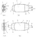
- FIG. 3 shows a top view of a tubular casing 1, the according to a prior art by simple flat pressing under e.g. Exposure to heat of the two end regions 2 and 2a the cover is welded at the end.
- the end regions 2 and 2a are deformed in a crescent shape and have sharp corners that are also above the rest Project the body of the case from the side.
- the end regions 2 and 2a become hard and can, as described above, e.g. when inserting between the turns one Winding with the sharp-edged corners the sensitive insulation of the winding wire or injure thin wires cut through.
- FIG. 2A shows the envelope 1 of FIG. 1 with a view of the one to be closed End face before pressing.
- the envelope 1 is in End area 2 on opposite sides towards the center folded that the end portion 2 through the formation the folds 3 tapers towards the front, as can be seen in FIG.
- the case end thus prepared is then made in a conventional manner pressed using heat or adhesive.
- the Fig. 2B shows the cover 1 closed on one side with itself wedge-shaped tapering end region 2 according to FIG. 1.
- FIG.4A 4 shows a casing 1 according to FIG Component 5 is equipped, the connections 6 on one side are brought out.
- the cap-shaped shell 1 protrudes with the open end of the component 5 sufficiently far so that the End region 2a is long enough to form folds 4.
- Fig.4A 4 shows a view of the front with the led out Connections 6. As shown in Fig.4A, arise the folds 4 by wrapping in the casing material the connections 6, so that the wedge-shaped tapered end region 2a lies closely against the connections 6. By a subsequent oneshrinking process, the folds 4 are fixed, whereby at the same time the casing material closely around the component 5 and the connections 6 puts.
- FIG. 5 shows an electrical protected by a sheath 7 Component 10, the connections 11 on opposite sides are brought out.
- the cover 7 is for assembly with a component 10 open on both sides.
- the shell 7 is over the end regions 7a and 7b longer than the component 10 to the Ensure formation of folds 8 and 9.
- Fig. 5A shows that Fig.5 in the view of the end faces with the led out Connections 11. Since the views of both end faces are the same there is no need for a double display.
- Fig.5A recognize leaves, in this case the formation of the folds 8 and 9 in that shown and described by FIGS. 2A and 2B Art.
- tubular casing material preferably made of a polyester or polyolefin material with or without shrink properties.
- shrinkable tube material for the casing 1 or 7 there are materials with different shrink rates on. With increasing thermal resilience of the hose material the shrinking capacity decreases.
- Shrinkable aramid paper reduces shrinkability Farther.
- the envelope must be folded 1 or 7, with their pressing a shrinking of the end regions 2 and 2a or 7a and 7b can be connected in egg to the extent that ensures that the casing 1 and 7 after shrinking onto an electrical component another one has tapered end regions 2 and 2a or 7a and 7b.
Landscapes
- Insulating Bodies (AREA)
- Insulation, Fastening Of Motor, Generator Windings (AREA)
- Details Of Indoor Wiring (AREA)
- Connections Effected By Soldering, Adhesion, Or Permanent Deformation (AREA)
Description
- Fig.1
- eine einseitig verschlossene schlauchförmige Hülle gemäß der Erfindung in Draufsicht.
- Fig.2A
- die Hülle gemäß Fig.1 in Stirnansicht mit faltenförmig eingeschlagenen Seiten vor dem Verpressen.
- Fig.2B
- die Hülle gemäß Fig.2A nach dem Verpressen.
- Fig.3
- in Draufsicht eine schlauchförmige Hülle mit beidseitigem Verschluß gemäß dem Stand der Technik.
- Fig.4
- ein in eine schlauchförmige Hülle gemäß der Erfindung eingeschweißtes elektrisches Bauteil mit einseitig herausgeführten Anschlüssen in Draufsicht.
- Fig.4A
- den Gegenstand der Fig.4 in Blickrichtung auf die Anschlüsse.
- Fig.5
- ein in eine schlauchförmige Hülle gemäß der Erfindung eingeschweißtes elektrisches Bauteil mit an gegenüberliegenden Seiten herausgeführten Anschlüssen in Draufsicht.
- Fig.5A
- den Gegenstand der Fig.5 in Blickrichtung auf eine der beiden Anschlüsse.
Claims (5)
- Schlauchförmige Hülle zur Isolation von elektromechanischen und/oder elektronischen Bauelementen, deren überstehende Endbereiche unter Einhalten der elektrisch notwendigen Abstände durch Flachpressen verschlossen sind,
dadurch gekennzeichnet, daß der zu verschließende Endbereich (2, 4 und 7a, 7b) der Hülle (1) vor dem Verpressen an gegenüberliegenden Seiten faltenförmig (Falten 3, 4 und 8, 9) eingeschlagen ist. - Hülle nach Anspruch 1, dadurch gekennzeichnet, daß die Falten (3, 4 und 8, 9) so tief sind, daß die verschlossenen Endbereiche (2, 4 und 7a, 7b) gegenüber dem übrigen Hüllenkörper keilförmig verjüngt sind.
- Hülle nach Anspruch 1 zur Isolation von Bauelementen mit einseitig herausgeführten Anschlüssen, dadurch gekennzeichnet, daß die Hülle (1) vor dem Bestücken mit einem Bauelement (5) durch einseitigen Verschluß des einen Endbereichs (2) zu einer Kappe ausgebildet ist und daß der andere Endbereich (2a) nach dem Einsetzen eines Bauelementes (5) anschließend in gleicher Weise verschlossen wird.
- Hülle nach Anspruch 1 zur Isolation von Bauelementen mit an gegenüberliegenden Seiten herausgeführten Anschlüssen, dadurch gekennzeichnet, daß das endseitige Verschließen der Hülle (7) nach dem Bestücken mit dem Bauelement (10) erfolgt.
- Hülle nach Anspruch 1, dadurch gekennzeichnet, daß sie ganz oder teilweise aus einem schrumpffähigen Material besteht.
Applications Claiming Priority (4)
| Application Number | Priority Date | Filing Date | Title |
|---|---|---|---|
| DE19539843 | 1995-10-26 | ||
| DE19539843 | 1995-10-26 | ||
| DE19621830 | 1996-05-31 | ||
| DE19621830A DE19621830A1 (de) | 1995-10-26 | 1996-05-31 | Schlauchförmige Hülle |
Publications (4)
| Publication Number | Publication Date |
|---|---|
| EP0771048A2 EP0771048A2 (de) | 1997-05-02 |
| EP0771048A3 EP0771048A3 (de) | 1998-12-16 |
| EP0771048B1 true EP0771048B1 (de) | 2001-01-03 |
| EP0771048B2 EP0771048B2 (de) | 2005-09-21 |
Family
ID=26019798
Family Applications (1)
| Application Number | Title | Priority Date | Filing Date |
|---|---|---|---|
| EP19960116862 Expired - Lifetime EP0771048B2 (de) | 1995-10-26 | 1996-10-21 | Schlauchförmige Hülle |
Country Status (2)
| Country | Link |
|---|---|
| EP (1) | EP0771048B2 (de) |
| ES (1) | ES2153928T5 (de) |
Families Citing this family (1)
| Publication number | Priority date | Publication date | Assignee | Title |
|---|---|---|---|---|
| DE102007018206B4 (de) * | 2007-04-16 | 2010-03-18 | Tmc Sensortechnik Gmbh | Temperaturbegrenzer sowie Verfahren zum Herstellen einer Hülle und Aufbringen derselben auf den Körper des Temperaturbegrenzers |
Citations (1)
| Publication number | Priority date | Publication date | Assignee | Title |
|---|---|---|---|---|
| US2997411A (en) * | 1956-10-02 | 1961-08-22 | Amp Inc | Closed end connector |
Family Cites Families (6)
| Publication number | Priority date | Publication date | Assignee | Title |
|---|---|---|---|---|
| US3385922A (en) * | 1965-07-27 | 1968-05-28 | Susquehanna Corp | Electrical connector with hermetic sealing utilizing polymerization |
| US3908267A (en) * | 1972-08-23 | 1975-09-30 | Stone Ind Corp | Method of applying an insulating connector |
| GB1604986A (en) * | 1978-01-09 | 1981-12-16 | Raychem Sa Nv | Clip |
| JPS5876214A (ja) * | 1981-11-02 | 1983-05-09 | Yoshino Kogyosho Co Ltd | 合成樹脂製チユ−ブ容器のシ−ル加工方法 |
| DE3439699A1 (de) * | 1984-10-30 | 1986-04-30 | Siemens AG, 1000 Berlin und 8000 München | Einlagen fuer schrumpfmuffen |
| DE4110455A1 (de) * | 1991-03-29 | 1992-10-01 | Schunk Ultraschalltechnik Gmbh | Elektrisch isolierende umhuellung sowie vorrichtung zum umschliessen einer verbindungsstelle mit einer solchen |
-
1996
- 1996-10-21 ES ES96116862T patent/ES2153928T5/es not_active Expired - Lifetime
- 1996-10-21 EP EP19960116862 patent/EP0771048B2/de not_active Expired - Lifetime
Patent Citations (1)
| Publication number | Priority date | Publication date | Assignee | Title |
|---|---|---|---|---|
| US2997411A (en) * | 1956-10-02 | 1961-08-22 | Amp Inc | Closed end connector |
Also Published As
| Publication number | Publication date |
|---|---|
| ES2153928T3 (es) | 2001-03-16 |
| EP0771048B2 (de) | 2005-09-21 |
| EP0771048A2 (de) | 1997-05-02 |
| EP0771048A3 (de) | 1998-12-16 |
| ES2153928T5 (es) | 2006-04-01 |
Similar Documents
| Publication | Publication Date | Title |
|---|---|---|
| DE69818110T2 (de) | Im voraus zusammengebautes elektrisches verbindungsbauteil | |
| DE69607112T2 (de) | Verbindung von energiekabeln | |
| EP1455375A1 (de) | Schmelzsicherungsbauelement mit einer temporär quasi-hermetischen Abdichtung des Innenraums | |
| DE19757587C2 (de) | Drathverbindungsstruktur für Verbinder und Herstellungsverfahren hierfür | |
| EP1620867B1 (de) | Transformator | |
| EP3648312A1 (de) | Vorgefertigte spule für einen direktantrieb | |
| EP0771048B2 (de) | Schlauchförmige Hülle | |
| DE19621830A1 (de) | Schlauchförmige Hülle | |
| DE10000604A1 (de) | Zündspule | |
| DE102020104653A1 (de) | Geschirmter elektrischer Verbinder | |
| DE4115020C3 (de) | Aderendhülse | |
| DE2549940C3 (de) | Selbstheilender elektrischer Kondensator | |
| DE19532559C2 (de) | Einteiliger Muffenkörper | |
| DE4125197C2 (de) | Wickelkondensator, insbesondere Rundwickelkondensator | |
| DE19702875A1 (de) | Spannungswandler | |
| DE3047796C2 (de) | Elektrischer Wickelkondensator | |
| DE102007018206B4 (de) | Temperaturbegrenzer sowie Verfahren zum Herstellen einer Hülle und Aufbringen derselben auf den Körper des Temperaturbegrenzers | |
| EP1622424A1 (de) | Verbindungsmuffe für Heizleiter | |
| DE69305481T2 (de) | Elektrisches Kabel | |
| EP0284927B1 (de) | Elektrischer Kondensator | |
| DE4220745A1 (de) | Abzweig- und/oder Verbindungsmuffe | |
| DE8136324U1 (de) | Elektrischer kondensator | |
| AT231555B (de) | In einen Gießharzkörper eingebettete Hochspannungswicklung für Transformatoren, Wandler od. dgl. | |
| CH656981A5 (de) | Erdverbindung fuer die metallkomponente eines schichtenmantels oder fuer einen bandschirm eines elektrischen kabels. | |
| EP0410101B1 (de) | Endverbindung von mindestens zwei abgeschirmten Kabeln |
Legal Events
| Date | Code | Title | Description |
|---|---|---|---|
| PUAI | Public reference made under article 153(3) epc to a published international application that has entered the european phase |
Free format text: ORIGINAL CODE: 0009012 |
|
| AK | Designated contracting states |
Kind code of ref document: A2 Designated state(s): DE ES FR IE IT NL |
|
| PUAL | Search report despatched |
Free format text: ORIGINAL CODE: 0009013 |
|
| AK | Designated contracting states |
Kind code of ref document: A3 Designated state(s): DE ES FR IE IT NL |
|
| 17P | Request for examination filed |
Effective date: 19990608 |
|
| GRAG | Despatch of communication of intention to grant |
Free format text: ORIGINAL CODE: EPIDOS AGRA |
|
| 17Q | First examination report despatched |
Effective date: 20000517 |
|
| GRAG | Despatch of communication of intention to grant |
Free format text: ORIGINAL CODE: EPIDOS AGRA |
|
| GRAH | Despatch of communication of intention to grant a patent |
Free format text: ORIGINAL CODE: EPIDOS IGRA |
|
| RAP1 | Party data changed (applicant data changed or rights of an application transferred) |
Owner name: TMC SENSORTECHNIK GMBH |
|
| GRAH | Despatch of communication of intention to grant a patent |
Free format text: ORIGINAL CODE: EPIDOS IGRA |
|
| GRAA | (expected) grant |
Free format text: ORIGINAL CODE: 0009210 |
|
| AK | Designated contracting states |
Kind code of ref document: B1 Designated state(s): DE ES FR IE IT NL |
|
| REG | Reference to a national code |
Ref country code: IE Ref legal event code: FG4D Free format text: GERMAN |
|
| REF | Corresponds to: |
Ref document number: 59606276 Country of ref document: DE Date of ref document: 20010208 |
|
| ITF | It: translation for a ep patent filed | ||
| ET | Fr: translation filed | ||
| REG | Reference to a national code |
Ref country code: ES Ref legal event code: FG2A Ref document number: 2153928 Country of ref document: ES Kind code of ref document: T3 |
|
| PLAV | Examination of admissibility of opposition |
Free format text: ORIGINAL CODE: EPIDOS OPEX |
|
| PLBQ | Unpublished change to opponent data |
Free format text: ORIGINAL CODE: EPIDOS OPPO |
|
| PLBI | Opposition filed |
Free format text: ORIGINAL CODE: 0009260 |
|
| PLAV | Examination of admissibility of opposition |
Free format text: ORIGINAL CODE: EPIDOS OPEX |
|
| PLBF | Reply of patent proprietor to notice(s) of opposition |
Free format text: ORIGINAL CODE: EPIDOS OBSO |
|
| 26 | Opposition filed |
Opponent name: THERMIK GERAETEBAU GMBH Effective date: 20011001 |
|
| NLR1 | Nl: opposition has been filed with the epo |
Opponent name: THERMIK GERAETEBAU GMBH |
|
| PLBF | Reply of patent proprietor to notice(s) of opposition |
Free format text: ORIGINAL CODE: EPIDOS OBSO |
|
| PLBF | Reply of patent proprietor to notice(s) of opposition |
Free format text: ORIGINAL CODE: EPIDOS OBSO |
|
| PLBO | Opposition rejected |
Free format text: ORIGINAL CODE: EPIDOS REJO |
|
| APAC | Appeal dossier modified |
Free format text: ORIGINAL CODE: EPIDOS NOAPO |
|
| APAC | Appeal dossier modified |
Free format text: ORIGINAL CODE: EPIDOS NOAPO |
|
| APBQ | Date of receipt of statement of grounds of appeal recorded |
Free format text: ORIGINAL CODE: EPIDOSNNOA3O |
|
| APAA | Appeal reference recorded |
Free format text: ORIGINAL CODE: EPIDOS REFN |
|
| APBU | Appeal procedure closed |
Free format text: ORIGINAL CODE: EPIDOSNNOA9O |
|
| PUAH | Patent maintained in amended form |
Free format text: ORIGINAL CODE: 0009272 |
|
| STAA | Information on the status of an ep patent application or granted ep patent |
Free format text: STATUS: PATENT MAINTAINED AS AMENDED |
|
| 27A | Patent maintained in amended form |
Effective date: 20050921 |
|
| AK | Designated contracting states |
Kind code of ref document: B2 Designated state(s): DE ES FR IE IT NL |
|
| APAH | Appeal reference modified |
Free format text: ORIGINAL CODE: EPIDOSCREFNO |
|
| NLR2 | Nl: decision of opposition |
Effective date: 20050921 |
|
| NLR3 | Nl: receipt of modified translations in the netherlands language after an opposition procedure | ||
| REG | Reference to a national code |
Ref country code: ES Ref legal event code: DC2A Date of ref document: 20051205 Kind code of ref document: T5 |
|
| ET3 | Fr: translation filed ** decision concerning opposition | ||
| PGFP | Annual fee paid to national office [announced via postgrant information from national office to epo] |
Ref country code: IE Payment date: 20091021 Year of fee payment: 14 |
|
| PGFP | Annual fee paid to national office [announced via postgrant information from national office to epo] |
Ref country code: NL Payment date: 20091027 Year of fee payment: 14 |
|
| REG | Reference to a national code |
Ref country code: NL Ref legal event code: V1 Effective date: 20110501 |
|
| REG | Reference to a national code |
Ref country code: IE Ref legal event code: MM4A |
|
| PG25 | Lapsed in a contracting state [announced via postgrant information from national office to epo] |
Ref country code: NL Free format text: LAPSE BECAUSE OF NON-PAYMENT OF DUE FEES Effective date: 20110501 |
|
| REG | Reference to a national code |
Ref country code: DE Ref legal event code: R097 Ref document number: 59606276 Country of ref document: DE |
|
| PG25 | Lapsed in a contracting state [announced via postgrant information from national office to epo] |
Ref country code: IE Free format text: LAPSE BECAUSE OF NON-PAYMENT OF DUE FEES Effective date: 20101021 |
|
| REG | Reference to a national code |
Ref country code: DE Ref legal event code: R040 Ref document number: 59606276 Country of ref document: DE Effective date: 20110913 |
|
| PGFP | Annual fee paid to national office [announced via postgrant information from national office to epo] |
Ref country code: ES Payment date: 20121023 Year of fee payment: 17 |
|
| REG | Reference to a national code |
Ref country code: ES Ref legal event code: FD2A Effective date: 20141107 |
|
| PG25 | Lapsed in a contracting state [announced via postgrant information from national office to epo] |
Ref country code: ES Free format text: LAPSE BECAUSE OF NON-PAYMENT OF DUE FEES Effective date: 20131022 |
|
| REG | Reference to a national code |
Ref country code: FR Ref legal event code: PLFP Year of fee payment: 20 |
|
| PGFP | Annual fee paid to national office [announced via postgrant information from national office to epo] |
Ref country code: IT Payment date: 20151026 Year of fee payment: 20 Ref country code: DE Payment date: 20150820 Year of fee payment: 20 |
|
| PGFP | Annual fee paid to national office [announced via postgrant information from national office to epo] |
Ref country code: FR Payment date: 20151026 Year of fee payment: 20 |
|
| REG | Reference to a national code |
Ref country code: DE Ref legal event code: R071 Ref document number: 59606276 Country of ref document: DE |