EP0770893B1 - Subträger zum Einschliessen einer optischen Faser und hermetische Durchführungsanordnung - Google Patents
Subträger zum Einschliessen einer optischen Faser und hermetische Durchführungsanordnung Download PDFInfo
- Publication number
- EP0770893B1 EP0770893B1 EP96202945A EP96202945A EP0770893B1 EP 0770893 B1 EP0770893 B1 EP 0770893B1 EP 96202945 A EP96202945 A EP 96202945A EP 96202945 A EP96202945 A EP 96202945A EP 0770893 B1 EP0770893 B1 EP 0770893B1
- Authority
- EP
- European Patent Office
- Prior art keywords
- fiber
- solder
- package
- aperture
- joint
- Prior art date
- Legal status (The legal status is an assumption and is not a legal conclusion. Google has not performed a legal analysis and makes no representation as to the accuracy of the status listed.)
- Expired - Lifetime
Links
- 239000013307 optical fiber Substances 0.000 title claims description 15
- 239000000835 fiber Substances 0.000 claims description 85
- 229910000679 solder Inorganic materials 0.000 claims description 59
- 230000005693 optoelectronics Effects 0.000 claims description 18
- 239000000758 substrate Substances 0.000 claims description 11
- 239000004593 Epoxy Substances 0.000 claims description 9
- 229910052737 gold Inorganic materials 0.000 claims description 6
- 239000011324 bead Substances 0.000 claims description 5
- 238000007747 plating Methods 0.000 claims description 3
- 229910052718 tin Inorganic materials 0.000 claims 3
- 238000001465 metallisation Methods 0.000 claims 1
- 229910052709 silver Inorganic materials 0.000 claims 1
- 238000000034 method Methods 0.000 description 12
- 239000000919 ceramic Substances 0.000 description 9
- 238000010438 heat treatment Methods 0.000 description 9
- 239000000463 material Substances 0.000 description 8
- 238000007789 sealing Methods 0.000 description 8
- 239000002184 metal Substances 0.000 description 6
- 229910052751 metal Inorganic materials 0.000 description 6
- 230000004907 flux Effects 0.000 description 5
- 239000011521 glass Substances 0.000 description 5
- PCHJSUWPFVWCPO-UHFFFAOYSA-N gold Chemical compound [Au] PCHJSUWPFVWCPO-UHFFFAOYSA-N 0.000 description 5
- 239000010931 gold Substances 0.000 description 5
- 238000004519 manufacturing process Methods 0.000 description 4
- 229910007116 SnPb Inorganic materials 0.000 description 3
- 239000004809 Teflon Substances 0.000 description 3
- 229920006362 Teflon® Polymers 0.000 description 3
- 238000005452 bending Methods 0.000 description 3
- 238000004140 cleaning Methods 0.000 description 3
- 238000003780 insertion Methods 0.000 description 3
- 230000037431 insertion Effects 0.000 description 3
- 230000008018 melting Effects 0.000 description 3
- 238000002844 melting Methods 0.000 description 3
- 230000003287 optical effect Effects 0.000 description 3
- 238000004806 packaging method and process Methods 0.000 description 3
- 239000004033 plastic Substances 0.000 description 3
- 238000005476 soldering Methods 0.000 description 3
- 239000002904 solvent Substances 0.000 description 3
- 239000000853 adhesive Substances 0.000 description 2
- 230000001070 adhesive effect Effects 0.000 description 2
- 239000003566 sealing material Substances 0.000 description 2
- 229910001369 Brass Inorganic materials 0.000 description 1
- RYGMFSIKBFXOCR-UHFFFAOYSA-N Copper Chemical compound [Cu] RYGMFSIKBFXOCR-UHFFFAOYSA-N 0.000 description 1
- 229910001030 Iron–nickel alloy Inorganic materials 0.000 description 1
- 229910007637 SnAg Inorganic materials 0.000 description 1
- 229910006913 SnSb Inorganic materials 0.000 description 1
- 229920006355 Tefzel Polymers 0.000 description 1
- 230000000712 assembly Effects 0.000 description 1
- 238000000429 assembly Methods 0.000 description 1
- 230000015572 biosynthetic process Effects 0.000 description 1
- 239000010951 brass Substances 0.000 description 1
- 229910052802 copper Inorganic materials 0.000 description 1
- 239000010949 copper Substances 0.000 description 1
- 230000008878 coupling Effects 0.000 description 1
- 238000010168 coupling process Methods 0.000 description 1
- 238000005859 coupling reaction Methods 0.000 description 1
- 230000001351 cycling effect Effects 0.000 description 1
- 230000032798 delamination Effects 0.000 description 1
- 238000005516 engineering process Methods 0.000 description 1
- QHSJIZLJUFMIFP-UHFFFAOYSA-N ethene;1,1,2,2-tetrafluoroethene Chemical compound C=C.FC(F)=C(F)F QHSJIZLJUFMIFP-UHFFFAOYSA-N 0.000 description 1
- 230000005496 eutectics Effects 0.000 description 1
- 238000011065 in-situ storage Methods 0.000 description 1
- 239000012212 insulator Substances 0.000 description 1
- 229910000833 kovar Inorganic materials 0.000 description 1
- 230000007774 longterm Effects 0.000 description 1
- 238000005272 metallurgy Methods 0.000 description 1
- 238000012536 packaging technology Methods 0.000 description 1
- 239000002245 particle Substances 0.000 description 1
- 229920000642 polymer Polymers 0.000 description 1
- 230000002459 sustained effect Effects 0.000 description 1
Images

Classifications
-
- G—PHYSICS
- G02—OPTICS
- G02B—OPTICAL ELEMENTS, SYSTEMS OR APPARATUS
- G02B6/00—Light guides; Structural details of arrangements comprising light guides and other optical elements, e.g. couplings
- G02B6/24—Coupling light guides
- G02B6/42—Coupling light guides with opto-electronic elements
- G02B6/4201—Packages, e.g. shape, construction, internal or external details
- G02B6/4219—Mechanical fixtures for holding or positioning the elements relative to each other in the couplings; Alignment methods for the elements, e.g. measuring or observing methods especially used therefor
- G02B6/4236—Fixing or mounting methods of the aligned elements
- G02B6/4238—Soldering
-
- G—PHYSICS
- G02—OPTICS
- G02B—OPTICAL ELEMENTS, SYSTEMS OR APPARATUS
- G02B6/00—Light guides; Structural details of arrangements comprising light guides and other optical elements, e.g. couplings
- G02B6/24—Coupling light guides
- G02B6/42—Coupling light guides with opto-electronic elements
- G02B6/4201—Packages, e.g. shape, construction, internal or external details
- G02B6/4248—Feed-through connections for the hermetical passage of fibres through a package wall
Definitions
- This invention relates to the field of packaging for optoelectronic devices and optical fiber locking and alignment.
- Optoelectronic transmitters and receivers that will be installed on commercial airplanes must operate for twenty years in potentially dusty, humid, corrosive and mechanically turbulent environments, and over a temperature range of -40 to +125 ° C. Long-term reliability in such hostile operating conditions requires hermetic sealing of the optoelectronic devices inside a metal hybrid package.
- optical signals are transferred to and from the optoelectronic device inside the package by an optical fiber.
- the fiber is solder sealed inside a nose tube which is brazed to the sidewall of the package.
- This type of hybrid electrical-optical package arrangement is commonly referred to as a "fiber-pigtailed" hybrid package.
- the process for interfacing the fiber to the package is called "pigtailing.”
- Pigtailing optoelectronic packages for avionics applications is challenging because of the scarcity of robust packaging technology solutions for problems crucial to successful operation and commercial success.
- the methods used in locking optical fibers inside optoelectronic packages must be reproducible, and the materials must be reliable.
- the materials used to seal optical fiber through the package sidewall must be reliable.
- Optical fiber locking and sealing manufacturing methods must be labor efficient with high yields.
- hermeticity must be sustained through 1,000 temperature cycles between -40° and +125°C.
- optical fiber-to-device coupling must remain efficient and stable after 1,000 temperature cycles between -40° and +125°C.
- a successful packaging technique must achieve both reliable hermetic sealing and precise optical fiber locking.
- Current techniques have not dealt with both of these packaging problems in a manner which meets the performance demands of avionics applications.
- an optical fiber is held in proper alignment by a fiber lock joint formed from a solder preform.
- the preform is heated to flow around the fiber and form the lock joint.
- the feedthrough joint where the fiber enters the package is heated to form a hermetic seal. Since package dimensions are small, heating the feedthrough joint will result in heating of the fiber lock joint area. Thus, the soldering hierarchy must be considered in choosing materials for the hermetic seal and the fiber lock joint.
- Soft, low melting point solders based on SnPb are sometimes used to form hermetic seals in less demanding applications.
- hermetic feedthrough joints using these soft solder materials do not maintain hermeticity after temperature cycling 1,000 times between-40°C and +125°C.
- Good reliability of hermetic fiber feedthrough may be obtained by sealing unmetallized fiber inside a metal (i.e., NiFe) tube with solder glass.
- the solder glass liquidus temperature is too high (>350°C) for implementing in situ solder glass sealing processes in packages containing fiber locking solders. Fiber locking solder joints inside the package will melt when the solder glass is reflowed at the seal nose tube.
- solder glass sealed nose tubes are not suitable for optoelectronic packages using a solder preform optical fiber locking technology.
- the preamble of claim 1 is based upon the optoelectronic package disclosed in EP 414 338.
- a solder lock joint on the substrate is formed of a reflowed solder preform, preferably a SnAg- based or SnSb- based solder. It surrounds at least part of the pretinned portion of the fiber so as to hold the fiber in its desired position, in alignment with an optoelectronic device in the package.
- the pretinning on the fiber results in a highly reliable solder lock joint.
- a solder seal joint forms a hermetic seal between the aperture and the fiber. This solder is preferably, 80Au20Sn, which has a melting point of 280°C.
- a nose tube with gold plating on its interior surface is mounted to the exterior of the housing.
- the fiber is a commercially available sleeved fiber which, in a preferred embodiment, has its sleeving terminated at one end with a cylindrical seal tube sleeve insert attached to the fiber with heat shrink tubing.
- This insert is a rigid sleeve which can be made of metal, plastic, ceramic, or the like.
- the optical fiber protrudes from the insert such that the entire pretinned portion of the fiber and a short length of polymer coated fiber protrudes from the rigid sleeve insert.
- the fiber is sealed into the insert with a high temperature adhesive such as an epoxy that is chemically resistant to solder flux and solder flux feedthrough cleaning solvents.
- the insert is designed to guide the fiber into the nose tube without bending or damaging the fiber.
- Figure 1 is a cross-sectional view of an optoelectronic package according to a preferred embodiment of the invention.
- Figures 2A, 2B, and 2C show in sequence the process of insertion of a fiber through a nose tube in a typical prior art device.
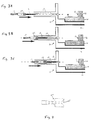
- Figures 3A, 3B, and 3C show in sequence the process of insertion of a fiber through a nose tube in an optoelectronic package according to a preferred embodiment of the invention.
- Figure 4 is a detail view of a seal tube sleeve insert of the preferred embodiment.
- Figure 5 is a cross-sectional view of an optical fiber with a seal tube sleeve insert mounted thereon in accordance with a preferred embodiment of the invention.
- Figures 6A and 6B show the sequence of insertion of a fiber through a solder preform and reflowing the preform according to a preferred embodiment of the invention.
- an optoelectronic package 10 includes an optoelectronic device 11 mounted on a wall 12 extending upward from a substrate 14 on the package floor 16.
- the substrate 14 is preferably a ceramic substrate which can be heated during the package assembly by running an electrical current through it, to create resistive heating.
- An optical fiber 18 extends through a nose tube 19 to an aperture 20 in the package wall 21 which is across form the optoelectronic device 19. This forms a fiber feedthrough joint 22.
- the nose tube 19 is preferably a Kovar tube with a gold-plated interior which is brazed to the side wall 21 of the package.
- the feedthrough joint 22 is hermetically sealed with a solder in a manner discussed below.
- the fiber 18 is held in alignment with the optoelectronic device 11 by a fiber lock joint 23, described in detail below.
- the fiber 18 will be a commercially available sleeved gold metallized optical fiber.
- the sleeving 17 is preferably a high temperature plastic that is physically and chemically stable over a wide temperature range. Examples of suitable sleeving materials which are readily commercially available are Teflon, Tefzel, Hytrel, Polysilicone and Polyfluorosilicone.
- the end of the fiber 18 which protrudes from the sleeving 17 is held in a cylindrical seal tube sleeve insert 24 which is held in place on the fiber end by heat shrink tubing 25.
- the cylindrical seal tube sleeve insert 24 in the pigtail assembly acts as a guide to position the fiber 18 through the nose tube 19 and into the package 10, eliminating the possibility of damaging the fiber during package assembly.
- Figures 2a - 2c illustrate how a fiber may be damaged without the sleeve insert 24 of the present invention.
- the fiber 18 extends from a flexible sleeving 28 of Teflon or the like.
- the fiber 18 sometimes protrudes from the sleeving 26 at an angle of less than 180 degrees.
- the fiber end face occasionally brushes the inside of the nose tube as shown in Figure 2c.
- the fiber end face may then be scratched or chipped, or the fiber may break. Even where damage does not occur, the assembly process can become expensive and time consuming since the operator must intervene by rotating the sleeving 26 until the fiber 18 finds the center of the nose tube 19.
- Figures 3a- 3c show how the seal tube sleeve insert 24 of the present invention guides the fiber 18 through the nose tube 19 so that the fiber 18 is centered within the nose tube 19.
- the sleeve insert 24, shown in detail in Figures 4 and 5, is preferably fabricated from a rigid material such as a ceramic, plastic or metal like copper or brass.
- the rigidity of the seal tube sleeve insert 24 causes the fiber 18 to reproducibly protrude out of the seal tube sleeve insert 24 at an angle very near to 180 degrees. Thus, it is easily guided through the nose tube 19 without contact between the fiber end face and the nose tube wall.
- Excessive fiber bending inside the nose-tube 19 may cause fiber breakage after locking and sealing the fiber into the package.
- the cylindrical insert also limits the amount of bending at the fiber-to-solder hermetic seal interface after the fiber is inserted into the package and/or after the fiber is epoxied inside the package nose tube.
- a seal between the sleeve insert 24 and fiber 18 is provided to prevent the solder flux and cleaning solvents used in the nose tube sealing process (described below) from migrating inside the insert 24 or sleeving 17.
- the sealing material should be a high temperature adhesive that is chemically resistant to solder flux and solder flux cleaning solvents.
- a suitable epoxy may be chosen for this purpose. It is generally difficult to reproducibly dispense and control the flow of sealing material (i.e. epoxy) at the fiber to sleeve insert interface, and the diameter of the epoxy bead. To overcome these difficulties, fabrication of the pigtail assembly is simplified by provision of a cupped cylinder insert end face.
- Figure 5 shows a cross-section of the seal tube sleeve insert 24 with an epoxy bead 27 in the cup 28 on the end face of the insert.
- the cup 28 assures that the epoxy bead 27 will be of a diameter less than that of the sleeving, and also inhibits wicking of the epoxy into the Teflon sleeve.
- a more reproducible fiber-to-sheathing seal joint diameter is obtained which results in less rework, a lower scrap rate, and a higher production yield.
- the optical fiber 18 is held in proper alignment by a fiber lock joint 23 formed from a solder preform 29.
- the preform 29 is heated to flow around the fiber 18 and form the lock joint 23.
- the heating is preferably accomplished by resistive heating of the ceramic substrate 14.
- the feedthrough joint 22 where the fiber 18 enters the package 10 is heated to form a hermetic seal. Since package dimensions are small, heating the feedthrough joint will result in heating of the fiber lock joint area.
- the soldering hierarchy is an important factor to consider in choosing solder materials for the hermetic seal and the fiber lock joint.
- solder material chosen for the lock joint Another important factor is the ability of the solder material chosen for the lock joint to reliably hold the fiber in the desired position.
- soft solders such as SnPb and PbIn, are ill-suited to this application because they lack rigidity and tend to crack and deform over the temperature range they will be exposed to in an avionics environment.
- hard SnAg-based and SnSb-based solders such as 96.5Sn3.5Ag solder and 95Sn5Sb are the preferred choices for fiber locking. They have a relatively high Young's Modulus and exhibit low creep characteristics; i.e., they do not develop appreciable deformation with temperature change and therefore will reliably hold the fiber 18 in proper alignment when cycled through large temperature variations. The liquidus temperatures of these solders are within a workable range when one considers the soldering hierarchy.
- T liquidus for 96.5Sn3.5Ag is 221°C and T liquidus for 95Sn5Sb is 240°C, while T liquidus for the preferred solder seal joint, 80Au20Sn (discussed more fully below), is 280°C. Due to its eutectic property and lower liquidus temperature 96.5Sn3.5Ag is the more preferable choice. Resistance to forming brittle AuSn 4 intermetallic at the metallized ceramic substrate-solder interface is another factor which makes 96.5Sn3.5Ag a preferable choice for the fiber lock joint.
- Heating of the package sidewall 21 to seal the fiber 18 in the feed through joint 22 will cause some heating of the ceramic substrate 14.
- tradeoffs must be made between ceramic substrate thickness, fiber locking solder melting point, distance between the fiber lock joint and the package sidewall, and metal base thermal conductivity and thickness.
- a 96.5Sn3.5Ag fiber locking solder will not reflow when the package sidewall is heated to about 300°C during the sealing process because the ceramic substrate 14 acts as a thermal insulator between the fiber lock joint and the floor 16 of the package.
- the metallurgy of the fiber-solder interface can be a source of performance problems.
- Brittle AuSn intermetallic may be formed at fiber-to-solder interface in solder lock joints containing SnAg-, SnSb- and SnPb-based solders. This brittle intermetallic at the fiber-to-solder interface can cause the fiber to delaminate from the solder. Delamination leads to the formation of metal flake particles which may contribute to electrical shorting, fiber shift, or attenuation of optical signal.
- solder-to-fiber interface The ability of brittle AuSn 4 to form at the solder-to-fiber interface is greatly reduced by selectively pre-tinning the end of the gold plated fiber with a solder such as, e.g., 96.5Sn3.5Ag, 95Sn5Sb, or the like. Fixturing techniques known to those skilled in the art allow the selective tinning process to be performed both simply and reproducibly in a manufacturing environment. The resulting solder lock joint is extremely reliable.
- about 0.100" at the end of the fiber is pre-tinned, so that only the portion of the fiber that contacts the fiber lock joint is pretinned.
- the gold plated area of the fiber that is not tinned is sealed into the nose tube with 80Au20Sn solder. No brittle intermetallic is formed between the gold plating on fiber and nose tube interior and the 80Au20Sn solder.
Landscapes
- Physics & Mathematics (AREA)
- General Physics & Mathematics (AREA)
- Optics & Photonics (AREA)
- Optical Couplings Of Light Guides (AREA)
Claims (10)
- Optoelektronisches Gehäuse (10) mitdadurch gekennzeichnet, dass ein Abschnitt des Endes der Faser (18), der sich innerhalb des Gehäuses befindet, selektiv vorverzinnt worden ist, wobei die Loteinschlussverbindung (23) aus einem ersten Lot gebildet ist, welches wenigstens einen Teil des vorverzinnten Abschnitts der Faser (18) umgibt, um sie so in einer gewünschten Position innerhalb des Gehäuses zu halten, und wobei die Lötverbindung (22) zur hermetischen Abdichtung aus einem zweiten, unterschiedlichen Lot gebildet ist, wobei das zweite Lot Au und Sn enthält.einem Gehäuse mit einer Seitenwand (21) mit einer Öffnung (20) dadurch und einem Boden (16) mit einem Substrat (14) darauf;einer optischen Faser (18) mit einem Ende, welches durch die Öffnung (20) in das Gehäuse ragt;einer Loteinschlussverbindung (23) auf dem Substrat (14);einer Lötverbindung (22), welche eine hermetische Dichtung zwischen der Öffnung (20) und der Faser (18) bildet,
- Gehäuse (10) nach Anspruch 1,
gekennzeichnet durch
einen Rohransatz (19) weicher an der Außenseite des Gehäuses befestigt ist, wobei ein Ende des Rohransatzes (18) die Öffnung (20) umgibt, wodurch sich die Faser (18) durch den Rohransatz (19) und die Öffnung (20) erstreckt, und wobei der Rohransatz (19) einen Au-Überzug an seiner Innenseite aufweist. - Gehäuse nach Anspruch 1 oder 2,
gekennzeichnet durch
einer steife Hülse (24), die um den Abschnitt der Faser (18) herum angeordnet ist, der in dem Rohransatz (19) liegt. - Gehäuse nach Anspruch 1, 2 oder 3,
dadurch gekennzeichnet, dass eine Metallisierung auf der Faser (18) Sn enthält. - Gehäuse nach einem der Ansprüche 1 bis 4,
dadurch gekennzeichnet, dass das erste Lot Sn und Ag enthält. - Gehäuse nach einem der Ansprüche 1 bis 5,
dadurch gekennzeichnet, dass das erste Lot 96,5Sn3,5Ag ist. - Gehäuse nach einem der Ansprüche 1 bis 6,
dadurch gekennzeichnet, dass das erste Lot Sn und Sb enthält. - Gehäuse nach einem der Ansprüche 1 bis 7,
dadurch gekennzeichnet, dass das erste Lot 95Sn5Sb ist. - Gehäuse nach einem der Ansprüche 1 bis 8,
dadurch gekennzeichnet, dass das erste Lot 80Au20Sn ist. - Gehäuse nach einem der Ansprüche 1 bis 9,
gekennzeichnet durch
einen Tropfen Epoxidharz (27), der eine Dichtung zwischen der Faser (18) und dem Ende der Hülse (24) bildet, welche näher an der Öffnung (20) ist, wobei die Hülse einen Napf (28) am Ende aufweist, der zum Aufnehmen des Tropfens (27) Epoxidharz ausgebildet ist.
Applications Claiming Priority (2)
| Application Number | Priority Date | Filing Date | Title |
|---|---|---|---|
| US548179 | 1995-10-25 | ||
| US08/548,179 US5692086A (en) | 1995-10-25 | 1995-10-25 | Optical fiber locking submount and hermetic feedthrough assembly |
Publications (3)
| Publication Number | Publication Date |
|---|---|
| EP0770893A2 EP0770893A2 (de) | 1997-05-02 |
| EP0770893A3 EP0770893A3 (de) | 1999-01-27 |
| EP0770893B1 true EP0770893B1 (de) | 2002-01-02 |
Family
ID=24187745
Family Applications (1)
| Application Number | Title | Priority Date | Filing Date |
|---|---|---|---|
| EP96202945A Expired - Lifetime EP0770893B1 (de) | 1995-10-25 | 1996-10-22 | Subträger zum Einschliessen einer optischen Faser und hermetische Durchführungsanordnung |
Country Status (4)
| Country | Link |
|---|---|
| US (1) | US5692086A (de) |
| EP (1) | EP0770893B1 (de) |
| JP (1) | JPH09166727A (de) |
| DE (1) | DE69618316T2 (de) |
Families Citing this family (36)
| Publication number | Priority date | Publication date | Assignee | Title |
|---|---|---|---|---|
| US6195495B1 (en) * | 1997-01-17 | 2001-02-27 | Ngk Insulators, Ltd. | Optical transmitting member-holding structure |
| JP2943760B2 (ja) | 1997-04-18 | 1999-08-30 | 日本電気株式会社 | 光ファイバ導入部の気密封止方法及び気密封止構造 |
| GB2339300B (en) * | 1998-07-06 | 2002-10-16 | Bookham Technology Ltd | A hermetically sealed optic fibre package and method of assembly |
| US6243528B1 (en) * | 1998-09-25 | 2001-06-05 | Agere Systems Optoelectronics Guardian Corp. | Fiber locking system |
| US6612752B2 (en) * | 1998-12-29 | 2003-09-02 | Corning Oti Spa | Sealed container for optical components and sealed feedthrough for optical fibers |
| US6253011B1 (en) | 1998-12-30 | 2001-06-26 | Mcdonnell Douglas Corporation | Micro-aligner for precisely aligning an optical fiber and an associated fabrication method |
| US6302593B1 (en) | 1998-12-30 | 2001-10-16 | Mcdonnell Douglas Corporation | Fiber optic connector with micro-alignable lenses and associated fabrication method |
| US6280100B1 (en) | 1998-12-30 | 2001-08-28 | Mcdonnell Douglas Corporation | Fiber optic connector with micro-alignable sensing fiber and associated fabrication method |
| US6164837A (en) * | 1998-12-30 | 2000-12-26 | Mcdonnell Douglas Corporation | Integrated microelectromechanical alignment and locking apparatus and method for fiber optic module manufacturing |
| US6174092B1 (en) | 1999-01-11 | 2001-01-16 | Oesys Photonics, Inc. | Method and apparatus for coupling an optical fiber to an optoelectronic device |
| US6427046B1 (en) | 2000-03-30 | 2002-07-30 | Schlumberger Technology Corporation | Optical feedthrough and method of making same |
| US6671450B2 (en) * | 2000-09-01 | 2003-12-30 | Lightwave Microsystems Corporation | Apparatus and method to metallize, reinforce, and hermetically seal multiple optical fibers |
| US6567604B1 (en) | 2000-10-25 | 2003-05-20 | Omm, Inc. | Indium plated package for an optical component and process therefore |
| US6498882B1 (en) * | 2000-11-28 | 2002-12-24 | Lightwave Microsystems Corporation | Assembly and method for reorganizing planar lightwave circuit channels |
| US6530701B2 (en) * | 2001-02-14 | 2003-03-11 | Jds Uniphase Inc. | Hermetic package with optical fiber feedthrough |
| US6627847B1 (en) * | 2001-06-28 | 2003-09-30 | Nortel Networks Limited | Method and apparatus for through-body optical component attachment using laser soldering |
| GB2377276A (en) * | 2001-06-29 | 2003-01-08 | Bookham Technology Plc | Reinforcing the fibre when mounting an optical fibre cable to an optical device |
| US6678458B2 (en) | 2001-08-17 | 2004-01-13 | Zynex Corporation | System and method for precise positioning of microcomponents |
| US6572743B2 (en) * | 2001-08-23 | 2003-06-03 | 3M Innovative Properties Company | Electroplating assembly for metal plated optical fibers |
| US6901203B1 (en) * | 2001-11-09 | 2005-05-31 | Diemat, Inc | Fiber optic feed-through tube and method for making the same |
| JP2003197134A (ja) * | 2001-12-27 | 2003-07-11 | Toshiba Corp | 画像表示装置およびその製造方法 |
| US6950594B2 (en) * | 2002-03-18 | 2005-09-27 | Intel Corporation | Method of attaching an optical fiber to a flexure |
| US6718764B1 (en) | 2002-06-28 | 2004-04-13 | Zyvex Corporation | System and method for microstructure positioning using metal yielding |
| CA2509530C (en) | 2002-12-10 | 2013-07-23 | Picometrix, Inc. | Precision optical fiber attachment using solder glass preform |
| US7341384B2 (en) * | 2005-03-30 | 2008-03-11 | The Boeing Company | Fiber optic transceiver module having built-in test capability and associated method |
| US7500793B2 (en) * | 2005-05-31 | 2009-03-10 | Greene, Tweed Of Delaware, Inc. | High-pressure/high-temperature seals between glass fibers and metals, downhole optical feedthroughs containing the same, and methods of preparing such seals |
| WO2007033611A1 (en) * | 2005-09-26 | 2007-03-29 | Hongkong Applied Science And Technology Research Institute Co., Ltd. | Opto-electronic device for optical fibre applications |
| US8023784B1 (en) * | 2009-03-16 | 2011-09-20 | The United States Of America As Represented By The Secretary Of The Navy | Optical subassembly package configuration |
| US8475056B2 (en) * | 2009-07-28 | 2013-07-02 | Jds Uniphase Corporation | Semiconductor device assembly |
| JP2013519917A (ja) * | 2010-02-12 | 2013-05-30 | エーゲンライト・コーポレーション | 一列に並んだ光ファイバーデバイス用のリード線付き貫通接続部を有する気密性パッケージおよび作製方法 |
| US8632262B2 (en) * | 2011-08-30 | 2014-01-21 | Kestrel Labs, Inc. | Laser to fiber optical coupling in photoplethysmography |
| JP5159939B1 (ja) * | 2011-10-18 | 2013-03-13 | 株式会社フジクラ | 光モジュールの製造方法 |
| CN103325163A (zh) * | 2013-05-18 | 2013-09-25 | 淮阴师范学院 | 电子封条锁及电子封识和查验系统 |
| US10139567B1 (en) * | 2017-10-10 | 2018-11-27 | The United States Of America As Represented By The Secretary Of The Navy | Dematable expanded beam fiber optic connector |
| US10481344B2 (en) * | 2017-11-21 | 2019-11-19 | Lumentum Operations Llc | High density optical fiber feedthrough |
| US11519816B2 (en) | 2019-02-18 | 2022-12-06 | The Boeing Company | Composite ply-by-ply damage assessment using correlation factors between finite element models (FEMs) and non-destructive evaluations (NDEs) |
Family Cites Families (18)
| Publication number | Priority date | Publication date | Assignee | Title |
|---|---|---|---|---|
| US1174137A (en) * | 1911-05-04 | 1916-03-07 | Edward Fulda | Process of making metallic fabric. |
| US2224145A (en) * | 1938-03-26 | 1940-12-10 | Nat Tube Co | Method of making pipe connections |
| US4252457A (en) * | 1978-06-27 | 1981-02-24 | Bell Telephone Laboratories, Incorporated | Optical fiber-to-metal hermetic seal |
| US4346294A (en) * | 1979-07-05 | 1982-08-24 | Burr-Brown Research Corp. | Low profile optical coupling to planar-mounted optoelectronic device |
| US4407561A (en) * | 1980-10-14 | 1983-10-04 | Hughes Aircraft Company | Metallic clad fiber optical waveguide |
| GB8310131D0 (en) * | 1983-04-14 | 1983-05-18 | British Telecomm | Sealing assembly |
| DE3334182A1 (de) * | 1983-09-21 | 1985-04-04 | Siemens AG, 1000 Berlin und 8000 München | Loeteinrichtung, insbesondere zum herstellen von nachtraeglichen verbindungsaenderungen an leiterplatten |
| US4741591A (en) * | 1984-12-20 | 1988-05-03 | Amp Incorporated | Optical fiber connector |
| US5222170A (en) * | 1987-04-03 | 1993-06-22 | Bt&D Technologies Ltd. | Optical fiber device fabrication |
| US5068865A (en) * | 1988-06-09 | 1991-11-26 | Nec Corporation | Semiconductor laser module |
| US5066091A (en) * | 1988-12-22 | 1991-11-19 | Kingston Technologies, Inc. | Amorphous memory polymer alignment device with access means |
| US4997253A (en) * | 1989-04-03 | 1991-03-05 | Tektronix, Inc. | Electro-optical transducer module and a method of fabricating such a module |
| US4936646A (en) * | 1989-08-23 | 1990-06-26 | Tektronix, Inc. | Temperature-compliant tube for fiber optic components |
| US5076688A (en) * | 1990-03-23 | 1991-12-31 | Amp Incorporated | Optical simulator with loop-back attenuator having metalized optical fiber |
| US5228101A (en) * | 1992-03-02 | 1993-07-13 | Motorola, Inc. | Electrical to optical links using metalization |
| US5412748A (en) * | 1992-12-04 | 1995-05-02 | Kabushiki Kaisha Toshiba | Optical semiconductor module |
| US5351329A (en) * | 1992-12-22 | 1994-09-27 | Alcatel Network Systems, Inc. | Method and apparatus for affixing an optic fiber tip in position with respect to a fiber communications circuit outside an optics package |
| US5613026A (en) * | 1993-12-28 | 1997-03-18 | Sumitomo Osaka Cement Co., Ltd. | Package structure for optical element and fibers and composite structure thereof |
-
1995
- 1995-10-25 US US08/548,179 patent/US5692086A/en not_active Expired - Fee Related
-
1996
- 1996-10-22 EP EP96202945A patent/EP0770893B1/de not_active Expired - Lifetime
- 1996-10-22 DE DE69618316T patent/DE69618316T2/de not_active Expired - Fee Related
- 1996-10-24 JP JP8282222A patent/JPH09166727A/ja active Pending
Also Published As
| Publication number | Publication date |
|---|---|
| DE69618316D1 (de) | 2002-02-07 |
| EP0770893A2 (de) | 1997-05-02 |
| US5692086A (en) | 1997-11-25 |
| EP0770893A3 (de) | 1999-01-27 |
| DE69618316T2 (de) | 2002-09-19 |
| JPH09166727A (ja) | 1997-06-24 |
Similar Documents
| Publication | Publication Date | Title |
|---|---|---|
| EP0770893B1 (de) | Subträger zum Einschliessen einer optischen Faser und hermetische Durchführungsanordnung | |
| EP0104882B1 (de) | Montageanordnungen zum Verbinden einer optischen Faser | |
| US4708429A (en) | Optical fiber assembly and optically coupled device package including same | |
| US4615031A (en) | Injection laser packages | |
| US6521989B2 (en) | Methods and apparatus for hermetically sealing electronic packages | |
| JP2706164B2 (ja) | 減結合ファイバ光学貫通アセンブリ | |
| CA1085663A (en) | Package for optical devices including optical fiber- to-metal hermetic seal | |
| EP0100086A2 (de) | Verfahren zur Herstellung von Einkapselungen von Laserdioden und Einkapselungen, die nach einem solchen Verfahren hergestellt sind | |
| JPS59113408A (ja) | 電子光学情報伝送装置用の送信又は受信のための装置 | |
| US5029968A (en) | Optoelectronic hybrid package assembly including integral, self-aligned fiber optic connector | |
| JP2001141969A (ja) | 光電子パッケージおよび集積マウントの製造方法 | |
| US6643446B2 (en) | Hermetic fiber ferrule and feedthrough | |
| JPH06300943A (ja) | 半導体素子モジュール | |
| US4168883A (en) | Arrangement to connect a laser to an optical fiber transmission line | |
| CA1096024A (en) | Package fpr light-triggered thyristor | |
| US6088504A (en) | In-line solder seal for optical fiber | |
| US7419311B2 (en) | Surface mount optical coupler, method of mounting the same, and method of producing the same | |
| US4741589A (en) | Coupler for optical waveguides | |
| US6474879B1 (en) | Post assembly metallization of a device to form hermetic seal | |
| CN100523883C (zh) | 精密光纤连接 | |
| US20040264889A1 (en) | Optoelectronic housings and methods of assembling optoelectronic packages | |
| JP2003107281A (ja) | 光ファイバ固定具 | |
| JPH0476446B2 (de) | ||
| JP2001066471A (ja) | 光モジュール | |
| JPH04130307A (ja) | 光半導体素子モジュール |
Legal Events
| Date | Code | Title | Description |
|---|---|---|---|
| PUAI | Public reference made under article 153(3) epc to a published international application that has entered the european phase |
Free format text: ORIGINAL CODE: 0009012 |
|
| AK | Designated contracting states |
Kind code of ref document: A2 Designated state(s): DE FR GB |
|
| PUAL | Search report despatched |
Free format text: ORIGINAL CODE: 0009013 |
|
| AK | Designated contracting states |
Kind code of ref document: A3 Designated state(s): DE FR GB |
|
| 17P | Request for examination filed |
Effective date: 19990709 |
|
| 17Q | First examination report despatched |
Effective date: 19990819 |
|
| GRAG | Despatch of communication of intention to grant |
Free format text: ORIGINAL CODE: EPIDOS AGRA |
|
| GRAG | Despatch of communication of intention to grant |
Free format text: ORIGINAL CODE: EPIDOS AGRA |
|
| GRAH | Despatch of communication of intention to grant a patent |
Free format text: ORIGINAL CODE: EPIDOS IGRA |
|
| GRAH | Despatch of communication of intention to grant a patent |
Free format text: ORIGINAL CODE: EPIDOS IGRA |
|
| GRAA | (expected) grant |
Free format text: ORIGINAL CODE: 0009210 |
|
| REG | Reference to a national code |
Ref country code: GB Ref legal event code: IF02 |
|
| AK | Designated contracting states |
Kind code of ref document: B1 Designated state(s): DE FR GB |
|
| REF | Corresponds to: |
Ref document number: 69618316 Country of ref document: DE Date of ref document: 20020207 |
|
| ET | Fr: translation filed | ||
| PLBE | No opposition filed within time limit |
Free format text: ORIGINAL CODE: 0009261 |
|
| STAA | Information on the status of an ep patent application or granted ep patent |
Free format text: STATUS: NO OPPOSITION FILED WITHIN TIME LIMIT |
|
| 26N | No opposition filed | ||
| PGFP | Annual fee paid to national office [announced via postgrant information from national office to epo] |
Ref country code: GB Payment date: 20031015 Year of fee payment: 8 |
|
| PGFP | Annual fee paid to national office [announced via postgrant information from national office to epo] |
Ref country code: FR Payment date: 20031020 Year of fee payment: 8 |
|
| PGFP | Annual fee paid to national office [announced via postgrant information from national office to epo] |
Ref country code: DE Payment date: 20031201 Year of fee payment: 8 |
|
| PG25 | Lapsed in a contracting state [announced via postgrant information from national office to epo] |
Ref country code: GB Free format text: LAPSE BECAUSE OF NON-PAYMENT OF DUE FEES Effective date: 20041022 |
|
| PG25 | Lapsed in a contracting state [announced via postgrant information from national office to epo] |
Ref country code: DE Free format text: LAPSE BECAUSE OF NON-PAYMENT OF DUE FEES Effective date: 20050503 |
|
| GBPC | Gb: european patent ceased through non-payment of renewal fee |
Effective date: 20041022 |
|
| PG25 | Lapsed in a contracting state [announced via postgrant information from national office to epo] |
Ref country code: FR Free format text: LAPSE BECAUSE OF NON-PAYMENT OF DUE FEES Effective date: 20050630 |
|
| REG | Reference to a national code |
Ref country code: FR Ref legal event code: ST |