EP0770751A1 - Device for holding a wing ajar - Google Patents
Device for holding a wing ajar Download PDFInfo
- Publication number
- EP0770751A1 EP0770751A1 EP96440080A EP96440080A EP0770751A1 EP 0770751 A1 EP0770751 A1 EP 0770751A1 EP 96440080 A EP96440080 A EP 96440080A EP 96440080 A EP96440080 A EP 96440080A EP 0770751 A1 EP0770751 A1 EP 0770751A1
- Authority
- EP
- European Patent Office
- Prior art keywords
- opening
- operating rod
- keeper
- relative
- door
- Prior art date
- Legal status (The legal status is an assumption and is not a legal conclusion. Google has not performed a legal analysis and makes no representation as to the accuracy of the status listed.)
- Granted
Links
Images

Classifications
-
- E—FIXED CONSTRUCTIONS
- E05—LOCKS; KEYS; WINDOW OR DOOR FITTINGS; SAFES
- E05C—BOLTS OR FASTENING DEVICES FOR WINGS, SPECIALLY FOR DOORS OR WINDOWS
- E05C17/00—Devices for holding wings open; Devices for limiting opening of wings or for holding wings open by a movable member extending between frame and wing; Braking devices, stops or buffers, combined therewith
- E05C17/02—Devices for holding wings open; Devices for limiting opening of wings or for holding wings open by a movable member extending between frame and wing; Braking devices, stops or buffers, combined therewith by mechanical means
- E05C17/04—Devices for holding wings open; Devices for limiting opening of wings or for holding wings open by a movable member extending between frame and wing; Braking devices, stops or buffers, combined therewith by mechanical means with a movable bar or equivalent member extending between frame and wing
- E05C17/12—Devices for holding wings open; Devices for limiting opening of wings or for holding wings open by a movable member extending between frame and wing; Braking devices, stops or buffers, combined therewith by mechanical means with a movable bar or equivalent member extending between frame and wing consisting of a single rod
- E05C17/24—Devices for holding wings open; Devices for limiting opening of wings or for holding wings open by a movable member extending between frame and wing; Braking devices, stops or buffers, combined therewith by mechanical means with a movable bar or equivalent member extending between frame and wing consisting of a single rod pivoted at one end, and with the other end running along a guide member
Definitions
- the invention relates to a locking fitting for a window, French window, door or the like, comprising a locking mechanism of the lever type comprising at least one operating rod extending at least partly in the rebate of the opening and controlled by movement by a drive mechanism actuated by a control element of the handle, key cylinder or the like type.
- the present invention will find its application in the field of building hardware.
- the locking fittings for tilt-and-turn window which not only allow the opening of the window by pivoting about a vertical axis of rotation, but also allow the ajar opening of this opening by tilting towards the interior of the dwelling around a horizontal axis of rotation materialized by the lower crossmember.
- the means for opening the opening are in the form of a compass arm connecting the upper cross member of the opening to a hinge fitting secured to the frame. This compass can be made free to rotate relative to the opening only under the action of a locking mechanism in the form of an operating rod.
- this type of locking device for a tilt-and-turn window is particularly convenient since the same handle allowing the user to lock or unlock the window also serves as a control for the ajar opening of the window. opening it.
- the present invention is intended to solve the aforementioned problems through a locking fitting provided with a device for holding the door in a partially open position which is capable of being activated by means of the locking mechanism, so that it turns out to be of great convenience of use.
- this locking fitting offers the possibility to limit the French opening angle of this opening in order to gain security, knowing that it can also, in certain cases, limit this angle of rotation of the opening relative to the sleeping frame to avoid damaging the window itself.
- a locking fitting for window, French window, door or the like comprising a locking mechanism, of the lever type, comprising at least one rod. of maneuver extending at least partly into the rebate of the opening and controlled in displacement by a drive mechanism actuated by a control element of the handle, key cylinder or the like, this locking fitting comprising at least one device to maintain, in a ajar position, the opening of said window or the like, this device being defined by a support fixed on the frame and on which one of the ends of a compass arm is articulated, the opposite end of which is fitted with hooking means, such as a nipple or a roller capable of sliding inside a keeper associated with a support mounted integral in displacement with an operating rod placed on the opening, this in order to limit the pivoting angle of the latter relative to the frame, said attachment means being able to disengage from said keeper as a result of a displacement of said operating rod under the impulse of the control element acting on the drive
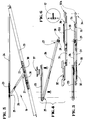
- the present invention relates to a locking fitting 1 visible in FIG. 2 which, inter alia, makes it possible to maintain in a ajar position 2 the opening 3 corresponding, as shown in FIG. 1, to a window, French window , door or the like 4.
- FIG. 1 a window whose opening 3 is pivotally mounted, about a vertical axis of rotation 5, on a frame 6.
- the present invention is in no way limited to such an opening mode which, when the opening 3 pivots towards the interior of the dwelling is usually defined as a French opening.
- the locking fitting 1 is also applicable to openings pivotally mounted about a horizontal axis of rotation on the frame, of the Italian-opening type.
- this locking fitting 1 comprises a locking mechanism 7 of the lever type, an embodiment of which is illustrated in FIG. 2. More precisely, this locking mechanism 7 comprises at least one operating rod 8, 8A; 9, 9A extending at least partially into the rebate 10 of the opening 3. The movement of these operating rods 8, 8A; 9, 9A is obtained by means of a drive mechanism 11 actuated by a control element 12 of the handle, button, key cylinder type, etc.
- this control element 12 can be mounted on the front upright 13 of the opening 3 so as to cooperate with one or more operating rods 8, 9 extending in rebate, upwards or downwards along this front upright 13 so as to intervene, for example, on one or more locking members 14, of the roller type or the like, capable of cooperating with keepers 15 arranged in concordance on the frame 6. Note that if the drive mechanism 11 intervenes on several operating rods 8, 9, these can move simultaneously in the same direction or in opposite directions .
- this or these operating rods 8; 9 can transmit their movement, through an appropriate bevel gear 18, 19, to sections of operating rod 8A; 9A, extending along the upper 20 and lower 21 crosspieces.
- this locking fitting 1 comprises a device 1A for keeping the opening leaf 3 ajar relative to the frame 6.
- a device 1A is intended to cooperate with one of said operating rods, 8, 8A ; 9, 9A.
- this device 1A in the context of the embodiment illustrated in the figures and which will now be described, there is talk of cooperation of this device 1A with one of the operating rods 8A; 9A extending along the upper 20 and lower 21 crosspieces of the opening 3.
- the locking fitting 1 comprises two devices 1A cooperating with each of the operating rods 8A; 9A being located, precisely, at the level of these upper 20 and lower 21 crosspieces of the opening 3.
- the present invention is in no way limited to such a design and it could perfectly be envisaged to implant a device 1A at the level of the front upright 13 of this opening 3 in cooperation with the front upright 22 of the frame 6, if it was a pivoting opening or the Italian for example.
- this device 1A comprises, according to the invention and as shown in Figures 3 to 10, a support 23 fixedly mounted on the frame 6, in this case in rabbet on the upper crosspiece 24 of the latter.
- a support 23 fixedly mounted on the frame 6, in this case in rabbet on the upper crosspiece 24 of the latter.
- a compass arm 26 On this fixed support 23 is articulated one of the ends of a compass arm 26, the opposite end 27 of which is fitted with hooking means 28 which, as visible in the various figures 4, 7, 8 and 10 can take the form of a circular stud 29, of axial T-shaped section.
- hooking means 28 which, as visible in the various figures 4, 7, 8 and 10 can take the form of a circular stud 29, of axial T-shaped section.
- these hooking means 28 must perform.
- these must be able to slide inside a keeper 30 associated with a support 31 mounted integral in displacement of an operating rod, in this case, 8A, placed on the opening 3.
- the keeper 30 has a T-
- this device 1A can advantageously serve to limit the opening angle of the opening 3 relative to the frame 6.
- this device 1A of the pivot axis 5 of the leaf 3 and the more the length of the compass arm 26 is increased the more this leaf 3 can pivot by a large angle of rotation relative to the frame 6.
- this angle of rotation it is , for example, possible to limit this angle of rotation to 90 ° this so as to avoid that the opening 3 cannot be supported on a possible lateral spine corresponding to the frame and which could, otherwise, serve as a lever arm to this opening 3 for a forced action on the articulation fittings which connect it to the frame 6.
- the locking fitting 1 can be equipped with two devices 1A, one of which intervenes, effectively, as a means allowing the door to be kept in a slightly ajar position, while the other, placed more near the pivot axis of the opening 3, limits the rotation of the latter when the first of these devices 1A is released.
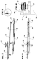
- Figures 4 and 5 illustrate, on the one hand, in perspective and exploded, and, on the other hand, in the form of a representation in elevation the arrangement made by the different elements composing the device 1A, precisely when the opening 3 is brought into such a ajar position.
- Figures 4 and 5, as well as Figures 7 and 8 illustrate, also, an embodiment of the means 32 allowing the connection of the support 31 at the end of an operating rod 8A, knowing, in this regard, that this support 31 can also be inserted in a longer operating rod 8A. Under these conditions, it is equipped with connection means 32, 32A at each of its ends 33, 34.
- the hooking means 28 equipping the end 27 of the compass arm 26 are able to disengage from said keeper 30 following a displacement consequently communicated to the support 31 by the operating rod 8A to which it is connected.
- this keeper 30 comprises, at one of its ends 35, an opening 36 authorizing the engagement and release through the latter, of the stud 29 constituting the hooking means 28 in the T-groove 30A.
- the locking mechanism 7, fitted to the window or the like 4 must be designed so that it is possible, once the opening 3 unlocked, to confer on the element 12, therefore on the operating rod 8A , at least two positions, one of which activates the device 1A to authorize only a cracking of this opening 3 and the other of which generates free rotation or a rotation of greater amplitude of this opening 3 by relative to the frame 6, this, for example, to allow cleaning of the exterior glazed surface of a window.
- the locking fitting 1 comprises two devices 1A, one of which is disposed closer than the other to the pivot axis 5 of the leaf 3, it can be provided that, during 'A first rotation of the handle 12, one simply obtains the unlocking allowing the first of these devices 1A to play its role of maintaining the opening 3 in a partially open position.
- the attachment means 28 corresponding to this first device 1A are able to release from the keeper 30, making, finally, this first device 1A inactive.
- the second device 1A, placed closer to the pivot axis 5 of the opening 3 may itself remain active.
- the opening 3 is able to open wide, while its rotation relative to the frame 6 remains limited.
- the device 1 can receive, at the height of the fixed support 23, for example, retaining means 37, shown in the form of an elastic clamp in the attached drawings, capable of holding the compass arm 26 in a position parallel to this fixed support 23 during a command for complete opening of the opening 3.
- retaining means 37 prevent, when the device 1A is deactivated, that the compass arm 26 does not pivot, freely in the direction of the opening 3 and, if necessary, opposes the closing of the latter.
- Said retaining means 37 in the form of an elastic clamp, are illustrated in detail in FIG. 10. Thus, they can be either fixed on the fixed support 23 or attached with the latter to the frame 6.
- the device 1 retains the same configuration, whether it is located at the level of the upper crosspieces 20, 24, respectively, of the leaf 3 and of the frame 6 or at the level of their lower crosspiece .
- this device 1 it is also visible that it suffices to turn this device 1 in one direction or the other depending on whether the operating rod or rods 8, 8A; 9, 9A move in one direction or another or that the opening opens to the left or to the right.
Abstract
Description
L'invention concerne une ferrure de verrouillage pour fenêtre, porte-fenêtre, porte ou analogue, comportant un mécanisme de verrouillage du type crémone comprenant au moins une tringle de manoeuvre s'étendant au moins en partie en feuillure de l'ouvrant et commandé en déplacement par un mécanisme d'entraînement actionné par un élément de commande du type poignée, barillet à clé ou analogue.The invention relates to a locking fitting for a window, French window, door or the like, comprising a locking mechanism of the lever type comprising at least one operating rod extending at least partly in the rebate of the opening and controlled by movement by a drive mechanism actuated by a control element of the handle, key cylinder or the like type.
La présente invention trouvera son application dans le domaine de la quincaillerie du bâtiment.The present invention will find its application in the field of building hardware.
On connaît déjà un bon nombre de ferrures de verrouillage répondant à la description ci-dessus. A ce propos, l'on connaît tout particulièrement, les ferrures de verrouillage pour ouvrant oscillo-battant qui, non seulement, autorisent l'ouverture de l'ouvrant par pivotement autour d'un axe de rotation vertical, mais, en outre, permettent l'ouverture entrebâillée de cet ouvrant par basculement vers l'intérieur de l'habitation autour d'un axe de rotation horizontal matérialisé par la traverse inférieure. En fait, dans ce cas d'espèce, les moyens permettant d'entrebâiller l'ouvrant se présentent sous forme d'un bras de compas reliant la traverse supérieure de l'ouvrant à une ferrure d'articulation solidaire du dormant. Ce compas ne peut être rendu libre en rotation par rapport à l'ouvrant que sous l'action d'un mécanisme de verrouillage sous forme d'une tringle de manoeuvre. Celle-ci est placée en feuillure au niveau du chant supérieur de cet ouvrant et dont la commande en déplacement est assurée par l'intermédiaire d'un mécanisme d'entraînement approprié. Sur ce dernier agit l'usager au moyen d'un élément de commande, tel qu'une poignée. Plus précisément, sous l'action de cette poignée et, donc, du déplacement de la tringle de manoeuvre, il en résulte le déplacement d'un organe d'accrochage, sous forme d'un téton associé à la tringle de manoeuvre, par rapport à une gâche précisément positionnée sur ledit bras de compas. Ce n'est que dans ces conditions que ledit bras de compas peut, effectivement, librement pivoter sur l'ouvrant.A good number of locking fittings corresponding to the above description are already known. In this regard, we particularly know, the locking fittings for tilt-and-turn window which not only allow the opening of the window by pivoting about a vertical axis of rotation, but also allow the ajar opening of this opening by tilting towards the interior of the dwelling around a horizontal axis of rotation materialized by the lower crossmember. In fact, in this case, the means for opening the opening are in the form of a compass arm connecting the upper cross member of the opening to a hinge fitting secured to the frame. This compass can be made free to rotate relative to the opening only under the action of a locking mechanism in the form of an operating rod. This is placed in a rebate at the upper edge of this opening and the movement control of which is ensured by means of an appropriate drive mechanism. The user acts on the latter by means of a control element, such as a handle. More precisely, under the action of this handle and, therefore, of the displacement of the operating rod, this results in the displacement of a fastening member, in the form of a stud associated with the operating rod, relative to a keeper precisely positioned on said compass arm. It is only under these conditions that said compass arm can, in fact, freely pivot on the leaf.
Mécaniquement parlant, ce type de dispositif de verrouillage pour ouvrant oscillo-battant est particulièrement commode dans la mesure où la même poignée permettant à l'usager de verrouiller ou de déverrouiller la fenêtre, lui sert, également, de commande pour l'ouverture entrebâillée de l'ouvrant.Mechanically speaking, this type of locking device for a tilt-and-turn window is particularly convenient since the same handle allowing the user to lock or unlock the window also serves as a control for the ajar opening of the window. opening it.
Toutefois, comme on peut le constater dans le cadre de ces fenêtres ou portes-fenêtres oscillo-battantes, lorsqu'elles sont amenées dans leur position entrebâillée, l'aération se produit, nécessairement, en partie supérieure de l'ouvrant. Or, il est de plus en plus usuel que de telles fenêtres ou portesfenêtres s'étendent quasiment jusqu'au plafond d'une pièce. Il est évident, dans ces conditions, que l'aération peut s'avérer insuffisante, obligeant les usagers à ouvrir la fenêtre ou porte-fenêtre à la française pour obtenir le résultat recherché. Toutefois, il sont obligés du même coup, à renoncer à la sécurité que leur procure la position en abattant. Tout particulièrement, il est évident que dans une telle position en abattant, il n'y a aucun risque d'accident pour les occupants, ceux-ci ne peuvent pas, en effet, tomber par la fenêtre par inadvertance, ou encore lorsque l'usager a fait usage d'objets hétéroclites, pour bloquer l'ouvrant entrebâillé, lesquels peuvent provoquer le décrochage de l'ouvrant qui peut blesser l'usager lors de sa chute.However, as can be seen in the context of these tilt-and-turn windows or French windows, when they are brought into their ajar position, ventilation necessarily occurs in the upper part of the opening. However, it is more and more common that such windows or glass doors extend almost to the ceiling of a room. It is obvious, under these conditions, that ventilation may prove to be insufficient, forcing users to open the window or French window to obtain the desired result. However, they are forced at the same time, to give up the security that gives them the position by killing. In particular, it is obvious that in such a position when shooting down, there is no risk of accident for the occupants, they cannot, in fact, fall out of the window inadvertently, or even when the user made use of heterogeneous objects, to block the ajar opening, which can cause the opening of the opening which can injure the user during his fall.
L'on comprend, lorsque ces occupants sont des enfants, que l'on ne peut renoncer à cette sécurité en ouvrant un vantail à la française sous prétexte que l'aération obtenue dans la position en abattant est insuffisante.One understands, when these occupants are children, that one cannot give up this security by opening a leaf with the French on the pretext that the ventilation obtained in the position when knocking down is insufficient.
A ce propos, se pose, en outre, le problème technique consistant à faire en sorte que l'ouverture totale de l'ouvrant ne peut être obtenue que sous l'effet qu'une commande volontaire exécutée par des personnes autorisées. Ainsi, s'il faut empêcher, dans les locaux occupés par des enfants, par exemple, que les fenêtres puissent s'ouvrir en grand, il est nécessaire, toutefois, d'autoriser une telle ouverture pour permettre l'accès à la surface vitrée extérieure de la fenêtre en vue du nettoyage et/ou de l'entretien.In this connection, there is also the technical problem of ensuring that the complete opening of the opening can only be obtained under the effect of a voluntary order executed by authorized persons. Thus, if it is necessary to prevent, in rooms occupied by children, for example, that the windows can open wide, it is necessary, however, to authorize such an opening to allow access to the glazed surface window exterior for cleaning and / or maintenance.
Là encore dans une telle position d'ouverture totale de la fenêtre, il est peut être opportun de limiter l'angle de rotation de l'ouvrant par rapport au dormant de manière à éviter de détériorer les ferrures d'articulation. En effet, en raison de contraintes de construction mais aussi d'isolation par l'intérieur d'une habitation, il n'est pas rare qu'une fenêtre soit logée à l'intérieur même de l'encadrement délimitant l'ouverture dans la construction destinée à recevoir cette fenêtre. Dans ces conditions et lors de l'ouverture à la française de l'ouvrant, celui-ci vient prendre appui sur l'épine latérale de cet encadrement et si, par mégarde, on vient exercer une pression sur cet ouvrant en appui sur l'épine latérale, celle-ci crée un bras de levier d'où résulte une transmission démultipliée de la pression sur les ferrures d'articulation qui, bien sûr, ne peuvent pas toujours résister à de telles contraintes.Again in such a fully open position of the window, it may be appropriate to limit the angle of rotation of the opening relative to the frame so as to avoid damaging the hinge fittings. Indeed, due to construction constraints but also to insulation from inside a house, it is not uncommon for a window to be housed inside the frame defining the opening in the construction intended to receive this window. Under these conditions and during the French opening of the opening, it comes to bear on the lateral spine of this frame and if, inadvertently, one comes to exert pressure on this opening bearing on the lateral spine, this creates a lever arm which results in a multiplied transmission of pressure on the hinge fittings which, of course, cannot always resist such stresses.
Il existe déjà un certain nombre d'entrebâilleurs en mesure de limiter le pivotement de l'ouvrant dans le cas, par exemple, de son ouverture à la française. Toutefois, pour activer ce type d'entrebâilleurs, il est nécessaire d'intervenir, le plus fréquemment, sur des moyens de commande différents de ceux autorisant le verrouillage ou le déverrouillage de l'ouvrant. De tels entrebâilleurs rendent obligatoire, de ce fait, l'exécution d'une manipulation supplémentaire, souvent rédhibitoire, pour les activer. Finalement, ces entrebâilleurs nécessitant, le plus souvent, une pose en applique, ils remettent en question l'aspect esthétique de l'ouvrant.There are already a number of ajar devices able to limit the pivoting of the opening in the case, for example, of its French opening. However, to activate this type of gag, it is necessary to intervene, most frequently, on control means different from those authorizing the locking or unlocking of the opening. Such half-openers therefore make it compulsory to carry out an additional manipulation, often prohibitive, to activate them. Finally, these half-openers requiring, more often than not, a surface-mounted installation, they question the aesthetic appearance of the opening.
La présente invention se veut à même de résoudre les problèmes précités au travers d'une ferrure de verrouillage munie d'un dispositif pour maintenir l'ouvrant dans une position entrebâillée qui est susceptible d'être activée à l'aide du mécanisme de verrouillage, de sorte qu'il s'avère d'une grande commodité d'utilisation.The present invention is intended to solve the aforementioned problems through a locking fitting provided with a device for holding the door in a partially open position which is capable of being activated by means of the locking mechanism, so that it turns out to be of great convenience of use.
Ainsi, dans le cas tout particulier d'une fenêtre ou porte-fenêtre à ouverture à la française, c'est-à-dire par pivotement de l'ouvrant autour d'un axe de rotation vertical, cette ferrure de verrouillage offre la possibilité de limiter l'angle d'ouverture à la française de cet ouvrant en vue d'un gain de sécurité, sachant qu'elle peut également, dans certains cas de figure, limiter cet angle de rotation de l'ouvrant par rapport au cadre dormant pour éviter de détériorer la fenêtre proprement dite.Thus, in the very particular case of a window or French window with French opening, that is to say by pivoting of the sash around a vertical axis of rotation, this locking fitting offers the possibility to limit the French opening angle of this opening in order to gain security, knowing that it can also, in certain cases, limit this angle of rotation of the opening relative to the sleeping frame to avoid damaging the window itself.
L'invention telle que caractérisée dans les revendications répond à l'ensemble de ces problèmes et consiste en une ferrure de verrouillage pour fenêtre, porte-fenêtre, porte ou analogue, comportant un mécanisme de verrouillage, du type crémone, comprenant au moins une tringle de manoeuvre s'étendant au moins en partie en feuillure de l'ouvrant et commandée en déplacement par un mécanisme d'entraînement actionné par un élément de commande du type poignée, barillet à clé ou analogue, cette ferrure de verrouillage comportant au moins un dispositif pour maintenir, dans une position entrebâillée, l'ouvrant de ladite fenêtre ou analogue, ce dispositif étant défini par un support fixé sur le dormant et sur lequel est montée articulée l'une des extrémités d'un bras de compas dont l'extrémité opposée est munie de moyens d'accrochage, tels qu'un téton ou un rouleau à même de coulisser à l'intérieur d'une gâche associée à un support monté solidaire en déplacement d'une tringle de manoeuvre placée sur l'ouvrant, ceci pour limiter l'angle de pivotement de ce dernier par rapport au dormant, lesdits moyens d'accrochage étant aptes à se dégager de ladite gâche suite à un déplacement en conséquence de ladite tringle de manoeuvre sous l'impulsion de l'élément de commande agissant sur le mécanisme d'entraînement, en vue d'une ouverture plus importante de l'ouvrant.The invention as characterized in the claims addresses all of these problems and consists of a locking fitting for window, French window, door or the like, comprising a locking mechanism, of the lever type, comprising at least one rod. of maneuver extending at least partly into the rebate of the opening and controlled in displacement by a drive mechanism actuated by a control element of the handle, key cylinder or the like, this locking fitting comprising at least one device to maintain, in a ajar position, the opening of said window or the like, this device being defined by a support fixed on the frame and on which one of the ends of a compass arm is articulated, the opposite end of which is fitted with hooking means, such as a nipple or a roller capable of sliding inside a keeper associated with a support mounted integral in displacement with an operating rod placed on the opening, this in order to limit the pivoting angle of the latter relative to the frame, said attachment means being able to disengage from said keeper as a result of a displacement of said operating rod under the impulse of the control element acting on the drive mechanism, for a larger opening of the opening.
Les avantages découlant de la présente invention consistent, essentiellement, en ce que le dispositif permettant de maintenir l'ouvrant en position entrebâillée peut être directement commandé par la poignée ou le barillet à clé agissant sur le mécanisme de verrouillage. Finalement, ceci rend la ferrure de verrouillage particulièrement commode à manipuler. En outre, l'ensemble des éléments constituant cette ferrure de verrouillage, peuvent être implantés en feuillure de la fenêtre ou analogue ce qui la rend totalement invisible.The advantages arising from the present invention consist essentially in that the device making it possible to maintain the opening in the ajar position can be directly controlled by the handle or the key cylinder acting on the locking mechanism. Finally, this makes the locking fitting particularly convenient to handle. In addition, all of the elements constituting this locking fitting can be installed in the window rebate or the like which makes it completely invisible.
De plus, en venant limiter, au travers de cette ferrure de verrouillage, l'angle de rotation de l'ouvrant par rapport au dormant, dans le cadre d'une ouverture normale, par exemple, à la française, on répond, de manière avantageuse, à la difficulté d'obtenir une aération convenable ce qui n'est pas le cas pour les ouvrants oscillo-batttants installés comme il a été décrit dans la partie introductive. Simultanément, on répond à la notion de sécurité que requiert ce type d'ouverture entrebâillée d'une fenêtre, porte-fenêtre ou analogue.In addition, by limiting, through this locking fitting, the angle of rotation of the opening relative to the frame, in the context of a normal opening, for example, in French, we respond in a manner advantageous, to the difficulty of obtaining suitable ventilation which is not the case for the tilt-and-turn windows installed as described in the introductory part. At the same time, we respond to the concept of security required by this type of ajar opening of a window, French window or the like.
L'invention sera mieux comprise à la lecture de la description qui va suivre accompagnée des dessins se rapportant à un mode de réalisation donné à titre d'exemple.
- la figure 1 représente une vue schématisée et en perspective d'une fenêtre équipée d'une ferrure de verrouillage conforme à l'invention ;
- la figure 2 représente une vue schématisée de cette ferrure de verrouillage venant équiper un ouvrant tel que représenté dans la figure 1 ;
- la figure 3 est une représentation schématisée du dispositif permettant de maintenir entrebâillé l'ouvrant par rapport au cadre dormant ;
- la figure 4 est une vue schématisée en perspective et éclatée du dispositif tel que représenté dans la figure 3, la position prise par les éléments étant celle correspondant à l'ouvrant entrebâillé ;
- la figure 5 est une représentation en élévation de la configuration prise par les éléments du dispositif tel que représenté dans la figure 4 lorsque l'ouvrant est entrebâillé ;
- la figure 6 illustre un élément de commande, sous forme d'une poignée dans une position qui peut correspondre aux situations illustrées dans les figures 4 et 6 ;
- la figure 7 est une vue similaire à la figure 4, les éléments étant représentés dans une position correspondant à la libre rotation de l'ouvrant par rapport au dormant ;
- la figure 8 est une vue similaire à la figure 5 représentant la disposition des différents éléments composant le dispositif à même de maintenir l'ouvrant entrebâillé lorsque celui-ci est susceptible de pivoter, librement, par rapport au dormant ;
- la figure 9 est une vue analogue à la figure 6, illustrant la position prise par la poignée dans les situations représentées dans les figures 7 et 8 ;
- la figure 10 est une vue en coupe selon X-X de la figure 8.
- Figure 1 shows a schematic perspective view of a window fitted with a locking fitting according to the invention;
- 2 shows a schematic view of this locking fitting fitted to an opening as shown in Figure 1;
- Figure 3 is a schematic representation of the device for keeping the opening ajar relative to the frame;
- Figure 4 is a schematic perspective and exploded view of the device as shown in Figure 3, the position taken by the elements being that corresponding to the opening ajar;
- Figure 5 is an elevational representation of the configuration taken by the elements of the device as shown in Figure 4 when the opening is ajar;
- FIG. 6 illustrates a control element, in the form of a handle in a position which can correspond to the situations illustrated in FIGS. 4 and 6;
- Figure 7 is a view similar to Figure 4, the elements being shown in a position corresponding to the free rotation of the opening relative to the frame;
- Figure 8 is a view similar to Figure 5 showing the arrangement of the various elements making up the device able to keep the opening ajar when it is likely to pivot, freely, relative to the frame;
- Figure 9 is a view similar to Figure 6, illustrating the position taken by the handle in the situations shown in Figures 7 and 8;
- FIG. 10 is a sectional view along XX of FIG. 8.
La présente invention est relative à une ferrure de verrouillage 1 visible dans la figure 2 qui, entre autres, permet de maintenir dans une position entrebâillée 2 l'ouvrant 3 correspondant, tel que représenté dans la figure 1, à une fenêtre, porte-fenêtre, porte ou analogue 4.The present invention relates to a locking fitting 1 visible in FIG. 2 which, inter alia, makes it possible to maintain in a ajar position 2 the
A ce propos, il a été représenté dans la figure 1, une fenêtre dont l'ouvrant 3 est monté pivotant, autour d'un axe de rotation vertical 5, sur un dormant 6. Toutefois, la présente invention n'est nullement limitée à un tel mode d'ouverture qui, lorsque l'ouvrant 3 pivote vers l'intérieur de l'habitation est défini, habituellement, comme une ouverture à la française. Plus particulièrement, la ferrure de verrouillage 1 est également applicable à des ouvrants montés pivotants autour d'un axe de rotation horizontal sur le dormant, du type ouvrant à l'italienne.In this regard, it has been represented in FIG. 1, a window whose
Ainsi, cette ferrure de verrouillage 1, conforme à l'invention, comporte un mécanisme de verrouillage 7 du type crémone dont un mode de réalisation est illustré dans la figure 2. Plus précisément, ce mécanisme de verrouillage 7 comporte au moins une tringle de manoeuvre 8, 8A ; 9, 9A s'étendant au moins en partie en feuillure 10 de l'ouvrant 3. Le déplacement de ces tringles de manoeuvre 8, 8A ; 9, 9A est obtenu par l'intermédiaire d'un mécanisme d'entraînement 11 actionné par un élément de commande 12 du type poignée, bouton, barillet à clé, etc...Thus, this locking fitting 1, in accordance with the invention, comprises a
Tel que représenté dans les figures 1 et 2, cet élément de commande 12, plus particulièrement illustré sous forme d'une poignée, peut être monté sur le montant avant 13 de l'ouvrant 3 de manière à coopérer avec une ou plusieurs tringles de manoeuvre 8, 9 s'étendant en feuillure, vers le haut ou vers le bas le long de ce montant avant 13 de manière à intervenir, par exemple, sur un ou plusieurs organes de verrouillage 14, du type rouleau ou analogue, à même de coopérer avec des gâches 15 disposées en concordance sur le dormant 6. A noter que si le mécanisme d'entraînement 11 intervient sur plusieurs tringles de manoeuvre 8, 9, celles-ci peuvent se déplacer, simultanément, dans une même direction ou dans des directions opposées. En outre, à l'extrémité supérieure 16 et/ou inférieure 17 de l'ouvrant 3, cette ou ces tringles de manoeuvre 8 ; 9 peuvent transmettre leur mouvement, au travers d'un renvoi d'angle 18, 19 approprié, à des tronçons de tringle de manoeuvre 8A ; 9A, s'étendant le long des traverses supérieure 20 et inférieure 21.As shown in Figures 1 and 2, this
On se réfère, à présent, à l'ensemble des figures des dessins ci-joints.Reference is now made to all of the figures in the attached drawings.
Selon l'invention, cette ferrure de verrouillage 1 comporte un dispositif 1A pour maintenir entrebâillé l'ouvrant 3 par rapport au dormant 6. En fait, un tel dispositif 1A est destiné à coopérer avec l'une desdites tringles de manoeuvre, 8, 8A ; 9, 9A. A ce propos, dans le cadre du mode de réalisation illustré dans les figures et qui va, à présent, être décrit, il est question d'une coopération de ce dispositif 1A avec l'une des tringles de manoeuvre 8A ; 9A s'étendant le long des traverses supérieure 20 et inférieure 21 de l'ouvrant 3. On note, tout particulièrement que dans ce mode de réalisation illustré dans les figures, la ferrure de verrouillage 1 comporte deux dispositifs 1A coopérant avec chacune des tringles de manoeuvre 8A ; 9A se situant, précisément, au niveau de ces traverses supérieure 20 et inférieure 21 de l'ouvrant 3. Il est évident que la présente invention n'est nullement limitée à une telle conception et il pourrait parfaitement être envisagé une implantation d'un dispositif 1A au niveau du montant avant 13 de cet ouvrant 3 en coopération avec le montant avant 22 du dormant 6, s'il s'agissait d'un ouvrant pivotant où à l'italienne par exemple.According to the invention, this locking fitting 1 comprises a
En outre, de manière à faciliter la compréhension de cette description, il est fait référence, dans les lignes qui suivent, à un dispositif 1A intervenant entre la traverse supérieure 20 de l'ouvrant 3 et la traverse supérieure 24 du dormant 6 sachant que, quelle que soit son implantation et tel que cela ressortira de la description ci-dessous, ce dispositif 1A peut conserver une même configuration, y compris pour une utilisation droite ou gauche sur une fenêtre à ouverture à la française d'une manière générale pour tout type d'ouvrant non coulissant.In addition, in order to facilitate the understanding of this description, reference is made, in the following lines, to a
Ainsi, ce dispositif 1A comporte, selon l'invention et tel que représenté dans les figures 3 à 10, un support 23 monté fixe sur le dormant 6, dans ce cas en feuillure sur la traverse supérieure 24 de ce dernier. Sur ce support fixe 23 est montée articulée l'une 25 des extrémités d'un bras de compas 26 dont l'extrémité opposée 27 est munie de moyens d'accrochage 28 qui, tel que visible dans les différentes figures 4, 7, 8 et 10 peuvent emprunter la forme d'un téton 29 circulaire, de section axiale en forme de T. A noter, cependant, que d'autres formes de réalisation peuvent être envisagées en concordance avec la fonction que doivent assurer ces moyens d'accrochage 28. A ce propos, ceux-ci doivent être à même de coulisser à l'intérieur d'une gâche 30 associée à un support 31 monté solidaire en déplacement d'une tringle de manoeuvre, dans ce cas, 8A, placée sur l'ouvrant 3. En fait, la gâche 30 comporte une rainure en T 30A dans laquelle peut se déplacer le téton 29.Thus, this
En fin de compte, c'est cette mobilité des moyens d'accrochage 28 à l'intérieur de la gâche 30, d'une part, et la longueur du bras de compas 26, d'autre part, sans compter le positionnement du dispositif 1A par rapport à l'axe de pivotement 5 de l'ouvrant 3 qui détermine l'amplitude de la mobilité de ce dernier par rapport au dormant 6 en position entrebâillée.In the end, it is this mobility of the attachment means 28 inside the
A ce propos, il convient de noter que ce dispositif 1A peut servir, avantageusement, de limiteur de l'angle d'ouverture de l'ouvrant 3 par rapport au dormant 6. En effet, l'on constate que plus l'on rapproche ce dispositif 1A de l'axe de pivotement 5 de l'ouvrant 3 et plus on augmente la longueur du bras de compas 26, plus cet ouvrant 3 peut pivoter selon un angle de rotation important par rapport au dormant 6. Tout particulièrement, il est, par exemple, possible de limiter cet angle de rotation à 90° ceci de manière à éviter que l'ouvrant 3 ne puisse prendre appui sur une éventuelle épine latérale correspondant à l'encadrement et qui pourrait, sans quoi, servir de bras de levier à cet ouvrant 3 pour une action forcée sur les ferrures d'articulation qui le relient au dormant 6.In this regard, it should be noted that this
Il est avantageux de noter que la ferrure de verrouillage 1 peut être équipée de deux dispositifs 1A dont l'un intervient, effectivement, en tant que moyen permettant de maintenir l'ouvrant dans une position faiblement entrebâillée, tandis que l'autre, placée plus près de l'axe de pivotement de l'ouvrant 3, limite la rotation de ce dernier lorsque le premier de ces dispositifs 1A est libéré.It is advantageous to note that the locking fitting 1 can be equipped with two
Le fonctionnement d'une telle ferrure de verrouillage, ainsi équipée de deux dispositifs 1A apparaîtra plus en avant dans la description.The operation of such a locking fitting, thus equipped with two
Les figures 4 et 5 illustrent, d'une part, en perspective et en éclaté, et, d'autre part, sous forme d'une représentation en élévation la disposition prise par les différents éléments composant le dispositif 1A, précisément lorsque l'ouvrant 3 est amené dans une telle position entrebâillée. Ces figures 4 et 5, ainsi que les figures 7 et 8 illustrent, également, un mode de réalisation des moyens 32 permettant le raccordement du support 31 à l'extrémité d'une tringle de manoeuvre 8A, sachant, à ce propos, que ce support 31 peut également venir s'intercaler dans une tringle de manoeuvre 8A plus longue. Dans ces conditions, il est équipé de moyens de raccordement 32, 32A à chacune de ses extrémités 33, 34.Figures 4 and 5 illustrate, on the one hand, in perspective and exploded, and, on the other hand, in the form of a representation in elevation the arrangement made by the different elements composing the
Selon l'invention, les moyens d'accrochage 28 équipant l'extrémité 27 du bras de compas 26 sont à même de se dégager de ladite gâche 30 suite à un déplacement en conséquence communiqué au support 31 par la tringle de manoeuvre 8A à laquelle il est raccordé.According to the invention, the hooking means 28 equipping the
Ainsi, cette gâche 30 comporte, à l'une de ses extrémités 35, une ouverture 36 autorisant l'engagement et le dégagement au travers de cette dernière, du téton 29 constituant les moyens d'accrochage 28 dans la rainure en T 30A.Thus, this
En fait, le mécanisme de verrouillage 7, équipant la fenêtre ou analogue 4, doit être conçu de sorte qu'il soit possible, une fois l'ouvrant 3 déverrouillé, de conférer à l'élément 12, donc à la tringle de manoeuvre 8A, au moins deux positions dont une active le dispositif 1A pour n'autoriser qu'un entrebâillement de cet ouvrant 3 et dont l'autre engendre la libre rotation ou une rotation d'amplitude plus importante de cet ouvrant 3 par rapport au dormant 6, ceci, en vue, par exemple, de permettre le nettoyage de la surface vitrée extérieure d'une fenêtre.In fact, the
Par conséquent, dans l'une de ces positions conférées à l'élément de commande 12, il doit en découler le dégagement des moyens d'accrochage 28 par rapport à la gâche 30 et, dans l'autre position, l'engagement de ces moyens d'accrochage 28 dans ladite gâche 30.Consequently, in one of these positions given to the
Ainsi, si l'on prend le cas d'un élément de commande 12 sous forme d'une poignée, l'on observe que cette poignée, lorsqu'elle est abaissée, telle que représentée dans la figure 2, engendre le verrouillage de l'ouvrant 3. Tandis que, ramenée dans une position horizontale, telle qu'illustrée dans la figure 6, les moyens d'accrochage 28 sont, tout comme dans le cas du verrouillage, maintenus engagés dans la gâche 30 correspondant au dispositif 1A n'autorisant qu'une ouverture limitée de l'ouvrant 3. En poursuivant le mouvement communiqué à cette poignée de manière à la ramener dans une position relevée telle qu'illustrée dans la figure 9, il peut en résulter un déplacement suffisant de la tringle de manoeuvre 8A pour obtenir le dégagement des moyens d'accrochage 28 de ladite gâche 30 au travers de son ouverture 36, autorisant, finalement, la libre rotation de l'ouvrant 3 par rapport au dormant 6.Thus, if we take the case of a
A supposer, cependant, que la ferrure de verrouillage 1, comporte deux dispositifs 1A dont l'un est disposé plus près que l'autre de l'axe de pivotement 5 de l'ouvrant 3, il peut être prévu que, au cours d'une première rotation de la poignée 12, l'on obtienne simplement le déverrouillage autorisant le premier de ces dispositifs 1A à jouer son rôle consistant à maintenir l'ouvrant 3 dans une position entrebâillée. Au cours d'une rotation complémentaire les moyens d'accrochage 28 correspondant à ce premier dispositif 1A sont en mesure de se dégager de la gâche 30, rendant, finalement, ce premier dispositif 1A inactif. Toutefois, le second dispositif 1A, placé plus près de l'axe de pivotement 5 de l'ouvrant 3 peut, lui, rester actif. Ainsi, l'ouvrant 3 est en mesure de s'ouvrir en grand, tandis que sa rotation par rapport au dormant 6 reste limitée. L'on peut, alors, imaginer qu'une dernière rotation de la poignée 12 soit possible qui conduit au dégagement des moyens d'accrochage 28 par rapport à la gâche 30 de ce second dispositif 1A de sorte que l'angle de rotation de l'ouvrant 3 par rapport au dormant 6 ne soit plus limité par la ferrure de verrouillage 1, objet de l'invention.Assuming, however, that the locking fitting 1 comprises two
Au vu de la description qui précède, on constate que, au travers de la ferrure de verrouillage 1, conforme à l'invention, il est possible de maintenir entrebâillé un vantail, notamment, à la française, sans qu'il n'y ait de risque pour les occupants, l'ouverture totale de cet ouvrant n'étant obtenue que sous l'effet d'une action volontaire et complémentaire de l'usager sur l'élément de commande 12.In view of the above description, it can be seen that, through the locking fitting 1, in accordance with the invention, it is possible to keep a leaf ajar, in particular, in the French style, without there being any risk for the occupants, the total opening of this opening being obtained only under the effect of a voluntary and complementary action of the user on the
A noter que le dispositif 1 peut recevoir, à hauteur du support fixe 23, par exemple, des moyens de retenue 37, représentés sous forme d'une pince élastique dans les dessins ci-joints, à même de maintenir le bras de compas 26 dans une position parallèle à ce support fixe 23 lors d'une commande d'ouverture complète de l'ouvrant 3. En fait, ces moyens de retenue 37 évitent, lorsque le dispositif 1A est désactivé, que le bras de compas 26 ne pivote, librement, en direction de l'ouvrant 3 et, le cas échéant, s'oppose à la fermeture de ce dernier.Note that the device 1 can receive, at the height of the fixed
Lesdits moyens de retenue 37, sous forme d'une pince élastique, sont illustrés de manière détaillée dans la figure 10. Ainsi, ils peuvent être, soit fixés sur le support fixe 23 soit rapportés avec ce dernier sur le dormant 6.Said retaining means 37, in the form of an elastic clamp, are illustrated in detail in FIG. 10. Thus, they can be either fixed on the fixed
Tel que cela apparaît clairement dans la figure 2, le dispositif 1 conserve une même configuration, qu'il se situe au niveau des traverses supérieures 20, 24, respectivement, de l'ouvrant 3 et du dormant 6 ou à hauteur de leur traverse inférieure. Sur cette même figure 2 il est par ailleurs visible qu'il suffit de retourner ce dispositif 1 dans un sens ou dans l'autre selon que la ou les tringles de manoeuvre 8, 8A ; 9, 9A se déplacent dans une direction ou dans une autre ou que l'ouvrant s'ouvre à gauche ou à droite. De plus, cela explique pourquoi la présente invention peut trouver son application dans tout type d'ouvrant non coulissant. Il est évident que du point de vue de la gestion de la fabrication et du stockage de ces ferrures de verrouillage, conformes à l'invention, cette standardisation présente un intérêt non négligeable.As it clearly appears in FIG. 2, the device 1 retains the same configuration, whether it is located at the level of the
Claims (8)
Applications Claiming Priority (2)
| Application Number | Priority Date | Filing Date | Title |
|---|---|---|---|
| FR9512903 | 1995-10-27 | ||
| FR9512903A FR2740504B1 (en) | 1995-10-27 | 1995-10-27 | DEVICE FOR HOLDING AN OPENING ELEMENT IN A LOCKED POSITION |
Publications (2)
| Publication Number | Publication Date |
|---|---|
| EP0770751A1 true EP0770751A1 (en) | 1997-05-02 |
| EP0770751B1 EP0770751B1 (en) | 2000-06-21 |
Family
ID=9484133
Family Applications (1)
| Application Number | Title | Priority Date | Filing Date |
|---|---|---|---|
| EP96440080A Revoked EP0770751B1 (en) | 1995-10-27 | 1996-10-09 | Device for holding a wing ajar |
Country Status (7)
| Country | Link |
|---|---|
| EP (1) | EP0770751B1 (en) |
| AT (1) | ATE194024T1 (en) |
| DE (1) | DE69608942T2 (en) |
| ES (1) | ES2149441T3 (en) |
| FR (1) | FR2740504B1 (en) |
| GR (1) | GR3034386T3 (en) |
| PT (1) | PT770751E (en) |
Cited By (9)
| Publication number | Priority date | Publication date | Assignee | Title |
|---|---|---|---|---|
| CN1298958C (en) * | 2003-04-06 | 2007-02-07 | 乐清市力兴塑窗配件有限公司 | Sliding door and window transmission lock |
| US7278185B2 (en) * | 2002-08-01 | 2007-10-09 | Securistyle Limited | Restricting device |
| EP2149661A1 (en) * | 2008-07-25 | 2010-02-03 | Sälzer Sicherheitstechnik GmbH | Explosion and burglar resistant building closure |
| CN101956361A (en) * | 2010-09-06 | 2011-01-26 | 徐州凯莫尔重工科技有限公司 | Manual locking mechanism supported by side door of spreading machine |
| CN103161382A (en) * | 2013-02-03 | 2013-06-19 | 深圳宝航建设集团股份有限公司 | Aluminium alloy casement window |
| EP4006277A1 (en) * | 2020-11-25 | 2022-06-01 | Giesse S.P.A. | Device for constraining the opening of doors or windows |
| EP4174265A1 (en) * | 2021-10-26 | 2023-05-03 | Gretsch-Unitas GmbH Baubeschläge | Wing assembly |
| EP4174264A1 (en) * | 2021-10-26 | 2023-05-03 | Gretsch-Unitas GmbH Baubeschläge | Wing assembly |
| EP4174266A1 (en) * | 2021-10-26 | 2023-05-03 | Gretsch-Unitas GmbH Baubeschläge | Wing assembly |
Families Citing this family (2)
| Publication number | Priority date | Publication date | Assignee | Title |
|---|---|---|---|---|
| CN110872769B (en) * | 2018-08-31 | 2022-05-06 | 青岛海尔洗衣机有限公司 | Clothes treating apparatus |
| CN110872768A (en) * | 2018-08-31 | 2020-03-10 | 青岛海尔洗衣机有限公司 | Clothes treating apparatus |
Citations (2)
| Publication number | Priority date | Publication date | Assignee | Title |
|---|---|---|---|---|
| FR2520038A1 (en) * | 1982-01-20 | 1983-07-22 | Ds Croisee | Clamp for holding door open - has wedge jamming connecting rod in slide guide in leaf |
| EP0380440A1 (en) * | 1989-01-25 | 1990-08-01 | Usm U. Schaerer Soehne Ag | Door or window |
-
1995
- 1995-10-27 FR FR9512903A patent/FR2740504B1/en not_active Expired - Fee Related
-
1996
- 1996-10-09 DE DE69608942T patent/DE69608942T2/en not_active Expired - Fee Related
- 1996-10-09 AT AT96440080T patent/ATE194024T1/en not_active IP Right Cessation
- 1996-10-09 EP EP96440080A patent/EP0770751B1/en not_active Revoked
- 1996-10-09 PT PT96440080T patent/PT770751E/en unknown
- 1996-10-09 ES ES96440080T patent/ES2149441T3/en not_active Expired - Lifetime
-
2000
- 2000-09-13 GR GR20000402076T patent/GR3034386T3/en not_active IP Right Cessation
Patent Citations (2)
| Publication number | Priority date | Publication date | Assignee | Title |
|---|---|---|---|---|
| FR2520038A1 (en) * | 1982-01-20 | 1983-07-22 | Ds Croisee | Clamp for holding door open - has wedge jamming connecting rod in slide guide in leaf |
| EP0380440A1 (en) * | 1989-01-25 | 1990-08-01 | Usm U. Schaerer Soehne Ag | Door or window |
Cited By (12)
| Publication number | Priority date | Publication date | Assignee | Title |
|---|---|---|---|---|
| US7278185B2 (en) * | 2002-08-01 | 2007-10-09 | Securistyle Limited | Restricting device |
| CN1298958C (en) * | 2003-04-06 | 2007-02-07 | 乐清市力兴塑窗配件有限公司 | Sliding door and window transmission lock |
| EP2149661A1 (en) * | 2008-07-25 | 2010-02-03 | Sälzer Sicherheitstechnik GmbH | Explosion and burglar resistant building closure |
| CN101956361A (en) * | 2010-09-06 | 2011-01-26 | 徐州凯莫尔重工科技有限公司 | Manual locking mechanism supported by side door of spreading machine |
| CN101956361B (en) * | 2010-09-06 | 2012-02-15 | 徐州凯莫尔重工科技有限公司 | Manual locking mechanism supported by side door of spreading machine |
| CN103161382A (en) * | 2013-02-03 | 2013-06-19 | 深圳宝航建设集团股份有限公司 | Aluminium alloy casement window |
| CN103161382B (en) * | 2013-02-03 | 2016-09-14 | 重庆慧思克科技有限公司 | A kind of aluminum alloy casement window |
| EP4006277A1 (en) * | 2020-11-25 | 2022-06-01 | Giesse S.P.A. | Device for constraining the opening of doors or windows |
| US11866966B2 (en) | 2020-11-25 | 2024-01-09 | Giesse S.P.A. | Device for constraining the opening of doors or windows |
| EP4174265A1 (en) * | 2021-10-26 | 2023-05-03 | Gretsch-Unitas GmbH Baubeschläge | Wing assembly |
| EP4174264A1 (en) * | 2021-10-26 | 2023-05-03 | Gretsch-Unitas GmbH Baubeschläge | Wing assembly |
| EP4174266A1 (en) * | 2021-10-26 | 2023-05-03 | Gretsch-Unitas GmbH Baubeschläge | Wing assembly |
Also Published As
| Publication number | Publication date |
|---|---|
| PT770751E (en) | 2000-11-30 |
| ATE194024T1 (en) | 2000-07-15 |
| DE69608942T2 (en) | 2001-02-01 |
| ES2149441T3 (en) | 2000-11-01 |
| FR2740504A1 (en) | 1997-04-30 |
| EP0770751B1 (en) | 2000-06-21 |
| DE69608942D1 (en) | 2000-07-27 |
| GR3034386T3 (en) | 2000-12-29 |
| FR2740504B1 (en) | 1998-02-27 |
Similar Documents
| Publication | Publication Date | Title |
|---|---|---|
| EP0770751B1 (en) | Device for holding a wing ajar | |
| EP0274975B1 (en) | Door or window locking device having means for locking the spindle | |
| FR2858008A3 (en) | MEANS OF TRANSPORT AND LIGHT TAMING DEVICE FOR USE WITH THIS MEDIUM MEANS, AND WINDOW COMPRISING THIS MEDIUM MEANS | |
| EP0436452A2 (en) | Door or window fitting, comprising means for holding the wing in open position | |
| FR2777588A1 (en) | LOCKING DEVICE FOR SLIDING DOOR | |
| EP0715048B1 (en) | Fastener for door, window or the like | |
| FR2844539A1 (en) | Operating handle e.g. for door or window of building, includes lever handle articulatingly connected to operating bar fixed to lock spindle that enables lever handle to be accommodated in handle body when not in use | |
| EP1329579B1 (en) | Lock fitting for barn door | |
| EP0769602B1 (en) | Hinge for a door, window or the like | |
| EP0924377B1 (en) | Hinge fitting for door, window or similar | |
| EP1842996B1 (en) | Espagnolette fitting capable of being embedded in a groove of a frame and comprising at least one lock follower | |
| EP0742333B1 (en) | Stay for door, window or similar | |
| EP1004735A1 (en) | Device preventing incorrect operation of doors, windows and the like comprising an espagnolette or an espagnolette lock | |
| EP0805250B1 (en) | Stay for door, window or the like | |
| EP1164244A2 (en) | Lifting device for a sash of a door, window or the like | |
| FR2497864A1 (en) | ADJUSTABLE CORNER FITTING ASSEMBLY LOCATED ON THE SIDE OF A SWINGING AND TILTING WINDOW | |
| FR2946682A1 (en) | CREMONE DEVICE FOR DOOR, WINDOW OR SIMILAR | |
| EP0743414A1 (en) | Security check for double winged window, doors or similar | |
| FR2729429A1 (en) | Lockable stay bar for windows and French windows with two leaves | |
| EP0296088A1 (en) | Operating device for an outwards opening wing of a door or a window | |
| EP4008863A1 (en) | Retaining device for joinery | |
| EP0992646B1 (en) | Espagnolette or espagnolette lock for doors, windows or the like | |
| FR3116849A1 (en) | Removable opening limiting and blocking device for sliding doors | |
| FR2845111A1 (en) | Door, gate or shutter retainer with catch on pivoted lever has rotary cam, sprung pusher with stop end and lock | |
| EP1878862B1 (en) | Locking mechanism for a window sash |
Legal Events
| Date | Code | Title | Description |
|---|---|---|---|
| PUAI | Public reference made under article 153(3) epc to a published international application that has entered the european phase |
Free format text: ORIGINAL CODE: 0009012 |
|
| AK | Designated contracting states |
Kind code of ref document: A1 Designated state(s): AT BE CH DE DK ES GB GR LI NL PT SE |
|
| 17P | Request for examination filed |
Effective date: 19970920 |
|
| 17Q | First examination report despatched |
Effective date: 19990519 |
|
| GRAG | Despatch of communication of intention to grant |
Free format text: ORIGINAL CODE: EPIDOS AGRA |
|
| GRAG | Despatch of communication of intention to grant |
Free format text: ORIGINAL CODE: EPIDOS AGRA |
|
| GRAH | Despatch of communication of intention to grant a patent |
Free format text: ORIGINAL CODE: EPIDOS IGRA |
|
| GRAH | Despatch of communication of intention to grant a patent |
Free format text: ORIGINAL CODE: EPIDOS IGRA |
|
| GRAA | (expected) grant |
Free format text: ORIGINAL CODE: 0009210 |
|
| AK | Designated contracting states |
Kind code of ref document: B1 Designated state(s): AT BE CH DE DK ES GB GR LI NL PT SE |
|
| PG25 | Lapsed in a contracting state [announced via postgrant information from national office to epo] |
Ref country code: AT Free format text: LAPSE BECAUSE OF FAILURE TO SUBMIT A TRANSLATION OF THE DESCRIPTION OR TO PAY THE FEE WITHIN THE PRESCRIBED TIME-LIMIT Effective date: 20000621 |
|
| REF | Corresponds to: |
Ref document number: 194024 Country of ref document: AT Date of ref document: 20000715 Kind code of ref document: T |
|
| REG | Reference to a national code |
Ref country code: CH Ref legal event code: EP |
|
| REF | Corresponds to: |
Ref document number: 69608942 Country of ref document: DE Date of ref document: 20000727 |
|
| GBT | Gb: translation of ep patent filed (gb section 77(6)(a)/1977) |
Effective date: 20000830 |
|
| PG25 | Lapsed in a contracting state [announced via postgrant information from national office to epo] |
Ref country code: SE Free format text: LAPSE BECAUSE OF FAILURE TO SUBMIT A TRANSLATION OF THE DESCRIPTION OR TO PAY THE FEE WITHIN THE PRESCRIBED TIME-LIMIT Effective date: 20000921 Ref country code: DK Free format text: LAPSE BECAUSE OF FAILURE TO SUBMIT A TRANSLATION OF THE DESCRIPTION OR TO PAY THE FEE WITHIN THE PRESCRIBED TIME-LIMIT Effective date: 20000921 |
|
| PGFP | Annual fee paid to national office [announced via postgrant information from national office to epo] |
Ref country code: CH Payment date: 20001026 Year of fee payment: 5 |
|
| PGFP | Annual fee paid to national office [announced via postgrant information from national office to epo] |
Ref country code: NL Payment date: 20001031 Year of fee payment: 5 |
|
| REG | Reference to a national code |
Ref country code: ES Ref legal event code: FG2A Ref document number: 2149441 Country of ref document: ES Kind code of ref document: T3 |
|
| REG | Reference to a national code |
Ref country code: PT Ref legal event code: SC4A Free format text: AVAILABILITY OF NATIONAL TRANSLATION Effective date: 20000905 |
|
| PGFP | Annual fee paid to national office [announced via postgrant information from national office to epo] |
Ref country code: BE Payment date: 20001214 Year of fee payment: 5 |
|
| PLBI | Opposition filed |
Free format text: ORIGINAL CODE: 0009260 |
|
| PLBF | Reply of patent proprietor to notice(s) of opposition |
Free format text: ORIGINAL CODE: EPIDOS OBSO |
|
| 26 | Opposition filed |
Opponent name: SIEGENIA-FRANK KG Effective date: 20010320 |
|
| NLR1 | Nl: opposition has been filed with the epo |
Opponent name: SIEGENIA-FRANK KG |
|
| PLBF | Reply of patent proprietor to notice(s) of opposition |
Free format text: ORIGINAL CODE: EPIDOS OBSO |
|
| PGFP | Annual fee paid to national office [announced via postgrant information from national office to epo] |
Ref country code: PT Payment date: 20011009 Year of fee payment: 6 |
|
| PGFP | Annual fee paid to national office [announced via postgrant information from national office to epo] |
Ref country code: GB Payment date: 20011010 Year of fee payment: 6 |
|
| PGFP | Annual fee paid to national office [announced via postgrant information from national office to epo] |
Ref country code: GR Payment date: 20011025 Year of fee payment: 6 |
|
| PGFP | Annual fee paid to national office [announced via postgrant information from national office to epo] |
Ref country code: ES Payment date: 20011026 Year of fee payment: 6 |
|
| PG25 | Lapsed in a contracting state [announced via postgrant information from national office to epo] |
Ref country code: LI Free format text: LAPSE BECAUSE OF NON-PAYMENT OF DUE FEES Effective date: 20011031 Ref country code: CH Free format text: LAPSE BECAUSE OF NON-PAYMENT OF DUE FEES Effective date: 20011031 Ref country code: BE Free format text: LAPSE BECAUSE OF NON-PAYMENT OF DUE FEES Effective date: 20011031 |
|
| REG | Reference to a national code |
Ref country code: GB Ref legal event code: IF02 |
|
| BERE | Be: lapsed |
Owner name: S.A. FERCO INTERNATIONAL FERRURES ET SERRURES DE Effective date: 20011031 |
|
| PG25 | Lapsed in a contracting state [announced via postgrant information from national office to epo] |
Ref country code: NL Free format text: LAPSE BECAUSE OF NON-PAYMENT OF DUE FEES Effective date: 20020501 |
|
| REG | Reference to a national code |
Ref country code: CH Ref legal event code: PL |
|
| NLV4 | Nl: lapsed or anulled due to non-payment of the annual fee |
Effective date: 20020501 |
|
| PG25 | Lapsed in a contracting state [announced via postgrant information from national office to epo] |
Ref country code: GB Free format text: LAPSE BECAUSE OF NON-PAYMENT OF DUE FEES Effective date: 20021009 |
|
| PG25 | Lapsed in a contracting state [announced via postgrant information from national office to epo] |
Ref country code: ES Free format text: LAPSE BECAUSE OF NON-PAYMENT OF DUE FEES Effective date: 20021010 |
|
| PGFP | Annual fee paid to national office [announced via postgrant information from national office to epo] |
Ref country code: DE Payment date: 20021220 Year of fee payment: 7 |
|
| PLAB | Opposition data, opponent's data or that of the opponent's representative modified |
Free format text: ORIGINAL CODE: 0009299OPPO |
|
| R26 | Opposition filed (corrected) |
Opponent name: SIEGENIA-AUBI KG. Effective date: 20010320 |
|
| PG25 | Lapsed in a contracting state [announced via postgrant information from national office to epo] |
Ref country code: PT Free format text: LAPSE BECAUSE OF NON-PAYMENT OF DUE FEES Effective date: 20030430 |
|
| PG25 | Lapsed in a contracting state [announced via postgrant information from national office to epo] |
Ref country code: GR Free format text: LAPSE BECAUSE OF NON-PAYMENT OF DUE FEES Effective date: 20030506 |
|
| GBPC | Gb: european patent ceased through non-payment of renewal fee |
Effective date: 20021009 |
|
| PLBC | Reply to examination report in opposition received |
Free format text: ORIGINAL CODE: EPIDOSNORE3 |
|
| PG25 | Lapsed in a contracting state [announced via postgrant information from national office to epo] |
Ref country code: DE Free format text: LAPSE BECAUSE OF NON-PAYMENT OF DUE FEES Effective date: 20040501 |
|
| REG | Reference to a national code |
Ref country code: ES Ref legal event code: FD2A Effective date: 20031112 |
|
| RDAF | Communication despatched that patent is revoked |
Free format text: ORIGINAL CODE: EPIDOSNREV1 |
|
| RDAG | Patent revoked |
Free format text: ORIGINAL CODE: 0009271 |
|
| STAA | Information on the status of an ep patent application or granted ep patent |
Free format text: STATUS: PATENT REVOKED |
|
| 27W | Patent revoked |
Effective date: 20050723 |