EP0770495B1 - Verfahren zur Herstellung einer lithographischen Druckplatte mit auf der Druckpresse stattfindenden Entwicklung - Google Patents
Verfahren zur Herstellung einer lithographischen Druckplatte mit auf der Druckpresse stattfindenden Entwicklung Download PDFInfo
- Publication number
- EP0770495B1 EP0770495B1 EP96202554A EP96202554A EP0770495B1 EP 0770495 B1 EP0770495 B1 EP 0770495B1 EP 96202554 A EP96202554 A EP 96202554A EP 96202554 A EP96202554 A EP 96202554A EP 0770495 B1 EP0770495 B1 EP 0770495B1
- Authority
- EP
- European Patent Office
- Prior art keywords
- imaging element
- image forming
- heat
- image
- forming layer
- Prior art date
- Legal status (The legal status is an assumption and is not a legal conclusion. Google has not performed a legal analysis and makes no representation as to the accuracy of the status listed.)
- Expired - Lifetime
Links
Images


Classifications
-
- B—PERFORMING OPERATIONS; TRANSPORTING
- B41—PRINTING; LINING MACHINES; TYPEWRITERS; STAMPS
- B41M—PRINTING, DUPLICATING, MARKING, OR COPYING PROCESSES; COLOUR PRINTING
- B41M5/00—Duplicating or marking methods; Sheet materials for use therein
- B41M5/26—Thermography ; Marking by high energetic means, e.g. laser otherwise than by burning, and characterised by the material used
- B41M5/36—Thermography ; Marking by high energetic means, e.g. laser otherwise than by burning, and characterised by the material used using a polymeric layer, which may be particulate and which is deformed or structurally changed with modification of its' properties, e.g. of its' optical hydrophobic-hydrophilic, solubility or permeability properties
- B41M5/366—Thermography ; Marking by high energetic means, e.g. laser otherwise than by burning, and characterised by the material used using a polymeric layer, which may be particulate and which is deformed or structurally changed with modification of its' properties, e.g. of its' optical hydrophobic-hydrophilic, solubility or permeability properties using materials comprising a polymeric matrix containing a polymeric particulate material, e.g. hydrophobic heat coalescing particles
-
- B—PERFORMING OPERATIONS; TRANSPORTING
- B41—PRINTING; LINING MACHINES; TYPEWRITERS; STAMPS
- B41C—PROCESSES FOR THE MANUFACTURE OR REPRODUCTION OF PRINTING SURFACES
- B41C1/00—Forme preparation
- B41C1/10—Forme preparation for lithographic printing; Master sheets for transferring a lithographic image to the forme
- B41C1/1008—Forme preparation for lithographic printing; Master sheets for transferring a lithographic image to the forme by removal or destruction of lithographic material on the lithographic support, e.g. by laser or spark ablation; by the use of materials rendered soluble or insoluble by heat exposure, e.g. by heat produced from a light to heat transforming system; by on-the-press exposure or on-the-press development, e.g. by the fountain of photolithographic materials
- B41C1/1025—Forme preparation for lithographic printing; Master sheets for transferring a lithographic image to the forme by removal or destruction of lithographic material on the lithographic support, e.g. by laser or spark ablation; by the use of materials rendered soluble or insoluble by heat exposure, e.g. by heat produced from a light to heat transforming system; by on-the-press exposure or on-the-press development, e.g. by the fountain of photolithographic materials using materials comprising a polymeric matrix containing a polymeric particulate material, e.g. hydrophobic heat coalescing particles
-
- B—PERFORMING OPERATIONS; TRANSPORTING
- B41—PRINTING; LINING MACHINES; TYPEWRITERS; STAMPS
- B41C—PROCESSES FOR THE MANUFACTURE OR REPRODUCTION OF PRINTING SURFACES
- B41C2210/00—Preparation or type or constituents of the imaging layers, in relation to lithographic printing forme preparation
- B41C2210/04—Negative working, i.e. the non-exposed (non-imaged) areas are removed
-
- B—PERFORMING OPERATIONS; TRANSPORTING
- B41—PRINTING; LINING MACHINES; TYPEWRITERS; STAMPS
- B41C—PROCESSES FOR THE MANUFACTURE OR REPRODUCTION OF PRINTING SURFACES
- B41C2210/00—Preparation or type or constituents of the imaging layers, in relation to lithographic printing forme preparation
- B41C2210/08—Developable by water or the fountain solution
-
- B—PERFORMING OPERATIONS; TRANSPORTING
- B41—PRINTING; LINING MACHINES; TYPEWRITERS; STAMPS
- B41C—PROCESSES FOR THE MANUFACTURE OR REPRODUCTION OF PRINTING SURFACES
- B41C2210/00—Preparation or type or constituents of the imaging layers, in relation to lithographic printing forme preparation
- B41C2210/24—Preparation or type or constituents of the imaging layers, in relation to lithographic printing forme preparation characterised by a macromolecular compound or binder obtained by reactions involving carbon-to-carbon unsaturated bonds, e.g. acrylics, vinyl polymers
Definitions
- the present invention relates to a method for making a lithographic printing plate. More in particular, the present invention relates to a method wherein the lithographic printing plate is developed on the printing press subsequent to image-wise exposure, which image-wise exposure may also be carried out on the printing press.
- Lithography is the process of printing from specially prepared surfaces, some areas of which are capable of accepting lithographic ink, whereas other areas, when moistened with water, will not accept the ink.
- the areas which accept ink form the printing image areas and the ink-rejecting areas form the background areas.
- a photographic material is made imagewise receptive to oily or greasy inks in the photo-exposed (negative-working) or in the non-exposed areas (positive-working) on a hydrophilic background.
- lithographic printing plates also called surface litho plates or planographic printing plates
- a support that has affinity to water or obtains such affinity by chemical treatment is coated with a thin layer of a photosensitive composition.
- Coatings for that purpose include light-sensitive polymer layers containing diazo compounds, dichromate-sensitized hydrophilic colloids and a large variety of synthetic photopolymers. Particularly diazo-sensitized systems are widely used.
- the exposed image areas become insoluble and the unexposed areas remain soluble.
- the plate is then developed with a suitable liquid to remove the diazonium salt or diazo resin in the unexposed areas.
- Lithocraft 10008 FOTOPLATETM is a diazo based printing plate that comprises on a paper support a hydrophilic layer on top of which is provided a diazo based photosensitive layer.
- a plate can be prepared by image-wise exposure of the lithographic printing plate precursor or imaging element, mounting the exposed imaging element on the press and wiping its surface with Lithocraft® 10008 Developer Desensitizer.
- the plate instructions also contemplate a method wherein no developer desensitizer is used. However, such method most often results in poor lithographic preformance so that in practice a Developer Desensitizer is almost always needed.
- a particular disadvantage of photosensitive imaging elements such as described above for making a printing plate is that they have to be shielded from the light. This is a particular disadvantage if on press development is contemplated since mounting the image-wise exposed imaging element is generally done in normal daylight so that the handling time for mounting the imaging element is limited. Moreover, diazo based aluminium type printing plates are completely unsuitable for on press development.
- An imaging element for use in accordance with the present invention is defined in present claim 1.
- the lithographic base comprises a flexible support, such as e.g. paper or plastic film, provided with a cross-linked hydrophilic layer.
- a particularly suitable cross-linked hydrophilic layer may be obtained from a hydrophilic binder cross-linked with a cross-linking agent such as formaldehyde, glyoxal, polyisocyanate or a hydrolysed tetra-alkylorthosilicate. The latter is particularly preferred.
- hydrophilic binder there may be used hydrophilic (co)polymers such as for example, homopolymers and copolymers of vinyl alcohol, acrylamide, methylol acrylamide, methylol methacrylamide, acrylic acid, methacrylic acid, hydroxyethyl acrylate, hydroxyethyl methacrylate or maleic anhydride/vinylmethylether copolymers.
- the hydrophilicity of the (co)polymer or (co)polymer mixture used is preferably the same as or higher than the hydrophilicity of polyvinyl acetate hydrolyzed to at least an extent of 60 percent by weight, preferably 80 percent by weight.
- the amount of crosslinking agent, in particular of tetraalkyl orthosilicate, is preferably at least 0.2 parts by weight per part by weight of hydrophilic binder, preferably between 0.5 and 5 parts by weight, more preferably between 1.0 parts by weight and 3 parts by weight.
- a cross-linked hydrophilic layer in a lithographic base used in accordance with the present embodiment preferably also contains substances that increase the mechanical strength and the porosity of the layer.
- colloidal silica may be used.
- the colloidal silica employed may be in the form of any commercially available water-dispersion of colloidal silica for example having an average particle size up to 40 nm, e.g. 20 nm.
- inert particles of larger size than the colloidal silica can be added e.g. silica prepared according to Stöber as described in J. Colloid and Interface Sci., Vol.
- alumina particles or particles having an average diameter of at least 100 nm which are particles of titanium dioxide or other heavy metal oxides.
- the thickness of a cross-linked hydrophilic layer in a lithographic base in accordance with this embodiment may vary in the range of 0.2 to 25 ⁇ m and is preferably 1 to 10 ⁇ m.
- cross-linked hydrophilic layers for use in accordance with the present invention are disclosed in EP-A 601240, GB-P-1419512, FR-P-2300354, US-P-3971660, US-P-4284705 and EP-A 514490.
- plastic film e.g. substrated polyethylene terephthalate film, cellulose acetate film, polystyrene film, polycarbonate film etc.
- the plastic film support may be opaque or transparent.
- the amount of silica in the adhesion improving layer is 200 mg per m 2 and 750 mg per m 2 .
- the ratio of silica to hydrophilic binder is preferably more than 1 and the surface area of the colloidal silica is preferably at least 300 m 2 per gram, more preferably a surface area of 500 m 2 per gram.
- an image forming layer on top of a hydrophilic surface there is provided an image forming layer.
- an image forming layer in connection with the present invention comprises thermoplastic polymer particles capable of coalescing under the influence of heat and dispersed in a hydrophilic binder.
- Suitable hydrophilic binders for use in an image forming layer in connection with this invention are for example synthetic homo or copolymers such as a polyvinylalcohol, a poly(meth)acrylic acid, a poly(meth)acrylamide, a polyhydroxyethyl(meth)acrylate, a polyvinylmethylether or natural binders such as gelatin, a polysacharide such as e.g. dextran, pullulan, cellulose, arabic gum, alginic acid.
- Hydrophobic thermoplastic polymer particles capable of coalescing under the influence of heat used in connection with the present invention preferably have a coagulation temperature above 35°C and more preferably above 50°C. Coagulation results from softening or melting of the thermoplastic polymer particles under the influence of heat.
- the coagulation temperature of the thermoplastic hydrophobic polymer particles There is no specific upper limit to the coagulation temperature of the thermoplastic hydrophobic polymer particles, however the temperature should be sufficiently below the decomposition of the polymer particles.
- the coagulation temperature is at least 10°C below the temperature at which the decomposition of the polymer particles occurs.
- said polymer particles When said polymer particles are subjected to a temperature above coagulation temperature they coagulate to form a hydrophobic agglomerate in the hydrophilic layer so that at these parts the hydrophilic layer becomes insoluble in plain water or an aqueous liquid.
- hydrophobic polymer particles for use in connection with the present invention are e.g. polyethylene, polyvinyl chloride, polymethyl (meth)acrylate, polyethyl (meth)acrylate, polyvinylidene chloride, polyacrylonitrile, polyvinyl carbazole etc. or copolymers thereof. Most preferably used is polyethylene.
- the weight average molecular weight of the polymers may range from 5,000 to 1,000,000g/mol.
- the hydrophobic particles may have a particle size from 0.01 ⁇ m to 50 ⁇ m, more preferably between 0.05mm and 10mm and most preferably between 0.05 ⁇ m and 2 ⁇ m.
- the polymer particles are present as a dispersion in the aqueous coating liquid of the image forming layer and may be prepared by the methods disclosed in US-P-3.476.937. Another method especially suitable for preparing an aqueous dispersion of the thermoplastic polymer particles comprises:
- the amount of hydrophobic thermoplastic polymer particles capable of coalescing under the influence of heat contained in the image forming layer is preferably between 20% by weight and 65% by weight and more preferably between 25% by weight and 55% by weight and most preferably between 30% by weight and 45% by weight.
- Suitable compounds capable of converting light into heat are preferably infrared absorbing components although the wavelength of absorption is not of particular importance as long as the absorption of the compound used is in the wavelength range of the light source used for image-wise exposure.
- Particularly useful compounds are for example dyes and in particular infrared dyes, carbon black, metal carbides, borides, nitrides, metal carbonitrides, bronze-structured oxides and oxides structurally related to the bronze family but lacking the A component e.g. WO 2.9 .
- conductive polymer dispersion such as polypyrrole or polyaniline-based conductive polymer dispersions.
- the lithographic performance and in particular the print endurance obtained depends on the heat-sensitivity of the imaging element. In this respect it has been found that carbon black yields very good and favorable results.
- a light to heat converting compound in connection with the present invention is most preferably added to the image forming layer but at least part of the light to heat converting compound may also be comprised in a neighbouring layer.
- Such layer can be for example the cross-linked hydrophilic layer of a lithographic base according to the second embodiment of lithographic bases explained above.
- the imaging element is image-wise exposed and subsequently is mounted on a print cylinder of a printing press.
- the printing press is then started and while the print cylinder with the imaging element mounted thereon rotates, the dampener rollers that supply dampening liquid are dropped on the imaging element and subsequent thereto the ink rollers are dropped.
- the dampener rollers that supply dampening liquid are dropped on the imaging element and subsequent thereto the ink rollers are dropped.
- the first clear and useful prints are obtained.
- the ink rollers and dampener rollers may be dropped simultaneously or the ink rollers may be dropped first.
- Suitable dampening liquids that can be used in connection with the present invention are aqueous liquids generally having an acidic pH and comprising an alcohol such as isopropanol.
- dampening liquids useful in the present invention there is no particular limitation and commercially available dampening liquids, also known as fountain solutions, can be used.
- an image-wise exposed imaging element e.g. a cotton pad or sponge soaked with water before mounting the imaging element on the press or at least before the printing press starts running. This will remove some non-image areas but will not actually develop the imaging element.
- it has the advantage that possible substantial contamination of the dampening system of the press and ink used is avoided.
- the imaging element is first mounted on the print cylinder of the printing press and then image-wise exposed directly on the press. Subsequent to exposure, the imaging element can be developed as described above.
- the printing plate of the present invention can also be used in the printing process as a seamless sleeve printing plate.
- the printing plate is soldered in a cylindrical form by means of a laser.
- This cylindrical printing plate which has as diameter the diameter of the print cylinder is slided on the print cylinder instead of applying in a classical way a classically formed printing plate. More details on sleeves are given in "Grafisch Niews" , 15, 1995, page 4 to 6.
- the imaging element may be image-wise exposed and subsequently developed by rinsing it with plain water.
- Image-wise exposure in connection with the present invention is preferably an image-wise scanning exposure involving the use of a laser or L.E.D.. It is highly preferred in connection with the present invention to use a laser emitting in the infrared (IR) and/or near-infrared, i.e. emitting in the wavelength range 700-1500nm. Particularly preferred for use in connection with the present invention are laser diodes emitting in the near-infrared.
- IR infrared
- near-infrared i.e. emitting in the wavelength range 700-1500nm.
- laser diodes emitting in the near-infrared are particularly preferred for use in connection with the present invention.
- a preferred imaging apparatus suitable for image-wise scanning exposure in accordance with the present invention preferably includes a laser output that can be provided directly to the imaging elements surface via lenses or other beam-guiding components, or transmitted to the surface of a blank imaging element from a remotely sited laser using a fiber-optic cable.
- a controller and associated positioning hardware maintains the beam output at a precise orientation with respect to the imaging elements surface, scans the output over the surface, and activates the laser at positions adjacent selected points or areas of the imaging element.
- the controller responds to incoming image signals corresponding to the original document and/or picture being copied onto the imaging element to produce a precise negative or positive image of that original.
- the image signals are stored as a bitmap data file on a computer.
- Such files may be generated by a raster image processor (RIP) or other suitable means.
- a RIP can accept Input data in page-description language, which defines all of the features required to be transferred onto the imaging element, or as a combination of page-description language and one or more image data files.
- the bitmaps are constructed to define the hue of the color as well as screen frequencies and angles in case of amplitude modulation screening.
- the present invention is particularly suitable for use in combination with frequency modulation screening as disclosed in e.g. EP-A 571010, EP-A 620677 and EP-A 620674.
- the imaging apparatus can operate on its own, functioning solely as a platemaker, or can be incorporated directly into a lithographic printing press having means for supplying a dampening liquid. In the latter case, printing may commence immediately after image-wise exposure and development, thereby reducing press set-up time considerably.
- the imaging apparatus can be configured as a flatbed recorder or as a drum recorder, with the lithographic plate blank mounted to the interior or exterior cylindrical surface of the drum.
- the exterior drum design is more appropriate to use in situ, on a lithographic press, in which case the print cylinder itself constitutes the drum component of the recorder or plotter.
- the requisite relative motion between the laser beam and the imaging element is achieved by rotating the drum(and the imaging element mounted thereon) about its axis and moving the beam parallel to the rotation axis, thereby scanning the imaging element circumferentially so the image "grows" in the axial direction.
- the beam can move parallel to the drum axis and, after each pass across the imaging element, increment angularly so that the image on the imaging element "grows" circumferentially.
- an image corresponding to the original will have been applied to the surface of the imaging element.
- the beam is drawn across either axis of the imaging element, and is indexed along the other axis after each pass.
- the requisite relative motion between the beam and the imaging element may be produced by movement of the imaging element rather than (or in addition to) movement of the beam.
- the beam is scanned, it is generally preferable (for reasons of speed) to employ a plurality of lasers and guide their outputs to a single writing array.
- the writing array is then indexed, after completion of each pass across or along the imaging element, a distance determined by the number of beams emanating from the array, and by the desired resolution (i.e. the number of image points per unit length.
- FIG. 1 of the drawings illustrates an exterior drum embodiment of an imaging system suitable for use in connection with the present invention.
- the assembly includes a cylinder 50 around which is wrapped an imaging element 55.
- Cylinder 50 includes a void segment 60, within which the outside margins of imaging element 55 are secured by conventional clamping means (not shown).
- the size of the void segment can vary greatly depending on the environment in which cylinder 50 is employed.
- cylinder 50 is straight forwardly incorporated into the design of a conventional lithographic press having means for supplying dampening liquid to the imaging element, and serves as the print cylinder of the press.
- imaging element 55 receives ink and dampening liquid from an ink train and a sequence of dampening cylinders respectively, whose terminal cylinders are in rolling engagement with cylinder 50.
- the latter cylinder also rotates in contact with a blanket cylinder, which transfers ink to the receiving element which is generally a paper sheet.
- the press may have more than one such printing assembly arranged in a linear array. Alternatively, a plurality of assemblies may be arranged about a large central impression cylinder in rolling engagement with all of the blanket cylinders.
- Cylinder 50 is supported in a frame and rotated by a standard electric motor or other conventional means (illustrated schematically in FIG. 2). The angular position of cylinder 50 is monitored by a shaft encoder (see FIG. 4).
- a writing array 65 mounted for movement on a lead screw 67 and a guide bar 69, traverses imaging element 55 as it rotates.
- Axial movement of writing array 65 results from rotation of a stepper motor 72, which turns lead screw 67 and thereby shifts the axial position of writing array 65.
- Stepper motor 72 is activated during the time writing array 65 is positioned over void 60, after writing array 65 has passed over the entire surface of imaging element 55. The rotation of stepper motor 72 shifts writing array 65 to the appropriate axial location to begin the next imaging pass.
- the axial index distance between successive imaging passes is determined by the number of imaging objects in writing array 65 and their configuration therein, as well as by the desired resolution.
- the lasers are preferably gallium-arsenide models, although any other lasers can be used.
- the cables that carry laser output are collected into a bundle 77 and emerge separately into writing array 65. It may prove desirable, in order to conserve power, to maintain the bundle in a configuration that does not require bending above the fiber's critical angle of refraction (thereby maintaining total internal reflection).
- a controller 80 actuates laser drivers 75 when the associated lasers reach appropriate points opposite imaging element 55, and in addition operates stepper motor 72 and the cylinder drive motor 82.
- Controller 80 receives data from two sources.
- the angular position of cylinder 50 with respect to writing array 65 is constantly monitored by a detector 85, which provides signals indicative of that position to controller 80.
- an image data source e.g., a computer
- the image data define points on imaging element 55 where image spots are to be written.
- Controller 80 therefore, correlates the instantaneous relative positions of writing array 65 and imaging element 55 (as reported by detector 85) with the image data to actuate the appropriate laser drivers at the appropriate times during scan of imaging element 55.
- the control circuitry required to implement this scheme is well-known in the scanner and plotter art.
- the laser output cables terminate in lens assemblies 96, mounted within writing array 65, that preferably precisely focus the beams onto the surface of imaging element 55.
- lens assemblies 96 mounted within writing array 65, that preferably precisely focus the beams onto the surface of imaging element 55.
- a suitable lens-assembly design is described below, for purposes of the present discussion, these assemblies are generically indicated by reference numeral 96.
- a suitable configuration is illustrated in FIG. 3 in this arrangement, lens assemblies 96 are staggered across the face of body 65.
- Controller 80 either receives image data already arranged into vertical columns, each corresponding to a different lens assembly or can progressively sample, in columnar fashion,the contents of a memory buffer containing a complete bitmap representation of the image to be transferred. In either case, controller 80 recognizes the different relative positions of the lens assemblies with respect to imaging element 55 and actuates the appropriate laser only when its associated lens assembly is positioned over a point to be imaged.
- FIG. 4 An alternative array design is illustrated in FIG. 4, which also shows the detector 85 mounted to the cylinder 50.
- the writing array designated by reference numeral 150
- the writing array 150 comprises a long linear body fed by fiber-optic cables drawn from bundle 77.
- the interior of writing array 150, or some portion thereof, contains threads that engage lead screw 67, rotation of which advances writing array 150 along imaging element 55 as discussed previously.
- Individual lens assemblies 96 are evenly spaced a distance B from one another. Distance B corresponds to the difference between the axial length of plate 55 and the distance between the first and last lens assembly; it represents the total axial distance traversed by writing array 150 during the course of a complete scan.
- stepper motor 72 rotates to advance writing array 150 an axial distance equal to the desired distance between imaging passes (i.e., the print density). This distance is smaller by a factor of n than the distance indexed by the previously described embodiment (writing array 65), where n is the number of lens assemblies included in writing array 65.
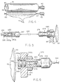
- FIGS. 5-7 Suitable means for guiding laser output to the surface of a imaging element are illustrated in FIGS. 5-7.
- FIG.5 shows a remote laser assembly that utilizes a fiber-optic cable to transmit laser pulses to the imaging element.
- a laser source 250 receives power via an electrical cable 252.
- Laser 250 is seated within the rear segment of a housing 255.
- Mounted within the forepart of housing are two or more focusing lenses 260a. 260b, which focus radiation emanating from laser 250 onto the end face of a fiber-optic cable 265, which is preferably (although not necessarily) secured within housing 255 by a removable retaining cap 267.
- Cable 265 conducts the output of laser 250 to an output assembly 270, which is illustrated in greater detail in FIG. 6.
- fiber-optic cable 265 enters the assembly 270 through a retaining cap 274 (which is preferably removable).
- Retaining cap 274 fits over a generally tubular body 276, which contains a series of threads 278.
- Mounted within the forepart of body 276 are two or more focusing lenses 280a, 280b, cable 265 is carried partway through body 276 by a sleeve 280.
- Body 276 defines a hollow channel between inner lens 280b and the terminus of sleeve 280, so the end face of cable 265 lies a selected distance A from inner lens 280b.
- the distance A and the focal lengths of lenses 280a, 280b are chosen so the at normal working distance from imaging element 55, the beam emanating from cable 265 will be precisely focused on the imaging elements surface. This distance can be altered to vary the size of an image feature.
- Body 276 can be secured to writing array 65 in any suitable manner.
- a nut 282 engages threads 278 and secures an outer flange 284 of body 276 against the outer face of writing array 65.
- the flange may, optionally, contain a transparent window 290 to protect the lenses from possible damage.
- the lens assembly may be mounted within the writing array on a pivot that permits rotation in the axial direction (i.e., with reference to FiG. 6, through the plane of the paper) to facilitate fine axial positioning adjustment. If the angle of rotation is kept to 4° or less, the circumferential error produced by the rotation can be corrected electronically by shifting the image data before it is transmitted to controller 80.
- FIG. 7 illustrates an alternative design in which the laser source irradiates the imaging elements surface directly, without transmission through fiber-optic cabling.
- laser source 250 is seated within the rear segment of an open housing 300.
- Mounted within the forepart of housing 300 are two or more focusing lenses 302a, 302b, which focus radiation emanating from laser 250 onto the surface of imaging element 55.
- the housing may, optionally, include a transparent window 305 mounted flush with the open end, and a heat sink 307.
- a suitable circuit for driving a diode-type (e.g., gallium arsenide) laser is illustrated schematically in FIG. 8. Operation of the circuit is governed by controller 80, which generates a fixed-pulse-width signal (preferably 5 to 20 ⁇ s in duration) to a highspeed, high-current MOSFET driver 325.
- the output terminal of driver 325 is connected to the gate of a MOSFET 327. Because driver 325 is capable of supplying a high output current to quickly charge the MOSFET gate capacitance, the turn-on and turn-off times for MOSFET 327 are very short (preferably within 0.5 ⁇ s) in spite of the capacitive load.
- the source terminal of MOSFET 327 is connected to ground potential.
- MOSFET 327 When MOSFET 327 is placed in a conducting state, current flows through and thereby activates a laser diode 330.
- a variable current-limiting resistor 332 is interposed between MOSFET 327 and laser diode 330 to allow adjustment of diode output. Such adjustment is useful, for example, to correct for different diode efficiencies and produce identical outputs in all lasers in the system, or to vary laser output as a means of controlling image size.
- a capacitor 334 is placed across the terminals of laser diode 330 to prevent damaging current overshoots,e.g., as a result of wire inductance combined with low laser-diode inter-electrode capacitance.
- a 0.2mm thick aluminium foil was degreased by immersing the foil in an aqueous solution containing 5g/l of sodium hydroxide at 50°C and rinsed with demineralised water.
- the foil was then electrochemically grained using an alternating current in an aqueous solution containing 4g/l of hydrochloric acid, 4 g/l of hydroboric acid and 0.5g/l of aluminium ions at a temperature of 35°C and a current density of 1200 A/m 2 to form a surface topography with an average center-line roughness R a of 0.5 ⁇ m.
- the aluminium foil was then etched with an aqueous solution containing 300g/l of sulfuric acid ate 60°C for 180 seconds and rinsed with demineralised water at 25°c for 30 seconds.
- the foil was subsequently subjected to anodic oxidation in an aqueous solution containing 200 g/l of sulfuric acid at a temperature of 45°C, a voltage of about 10V and a current density of 150 A/m 2 for about 300 seconds to form an anodic oxidation film of 3g/m 2 Al 2 O 3 , then washed with demineralised water, post treated with a solution containing 20 g/l of sodium bicarbonated at 40°C for 30s, subsequently rinsed with demineralised water of 20°C during 120s and dried.
- the obtained lithographic base was submersed in an aqueous solution containing 5% by weight of citric acid for 60s, rinsed with demineralised water and dried at 40°C.
- An imaging element according to the invention was produced by preparing the following coating composition and coating it to the above described lithographic base in an amount of 30g/m 2 (wet coating amount) and drying it at 35°C.
- An imaging element as described above was subjected to a scanning Nd YLF infrared laser emitting at 1050nm (scan speed 4m/s, spot size 15 ⁇ m and 670mW power on the surface of the imaging element).
- the obtained image-wise exposed imaging element was mounted on an ABDIC 360TM offset printing press equipped with a VARN KOMPACTM II dampening system.
- ink VanSon RB2329TM and as a dampening liquid G671cTM (3% in water) commercially available from Agfa-Geveart NV were used.
- the press was started by allowing the print cylinder with the imaging element mounted thereon to rotate.
- the dampener rollers of the press were dropped on the imaging elements surface to as to supply dampening liquid to the imaging element and after 10 revolutions of the print cylinder, the ink rollers were dropped to supply ink. After a further 10 revolutions, clear prints were obtained with no ink uptake in the non-image parts.
- An imaging element was prepared as described in example 1 with the exception that the submersion of the lithographic base in a citric acid solution was omitted and the lithographic base was directly coated with the coating composition.
- a printing plate was prepared as in example 1 and after a total of 20 revolutions of the print cylinder, clear prints were obtained without ink uptake in the non-image areas.
- the obtained dispersion was coated on a polyethyleneterephthalate film support (coated with a hydrophilic adhesion layer) to a wet coating thickness of 50 g/m 2 , dried at 30 °C. and subsequently hardened by subjecting it to a temperature of 57 °C for 1 week.
- An imaging element using the above described lithographic base and printing plate therefrom were then prepared as described in example 1. After 20 revolutions, clear prints without ink uptake in the non-image areas were obtained.
Landscapes
- Physics & Mathematics (AREA)
- Optics & Photonics (AREA)
- Thermal Sciences (AREA)
- Engineering & Computer Science (AREA)
- Manufacturing & Machinery (AREA)
- Manufacture Or Reproduction Of Printing Formes (AREA)
- Printing Plates And Materials Therefor (AREA)
Claims (9)
- Ein durch die nachstehenden Schritte gekennzeichnetes Verfahren zur Herstellung einer lithografischen Druckplatte :(1) Aufspannen eines Bilderzeugungselements auf eine Drucktrommel einer Druckpresse, wobei das Bilderzeugungselement :(i) eine lithografische Unterlage, die einen biegsamen Träger und eine vernetzte hydrophile Schicht enthält,(ii) eine bilderzeugende Schicht mit hydrophoben thermoplastischen, in einem hydrophilen, nicht oder nur leicht vernetzten Bindemittel dispergierten Polymerteilchen, die in der Lage sind, unter der Einwirkung von Wärme zu koaleszieren, wobei die bilderzeugende Schicht auf der hydrophilen Schicht vorliegt oder durch eine oder mehrere Zwischenschichten davon getrennt ist, und(iii)eine Verbindung enthält, die Licht in Wärme umzuwandeln vermag und in der bilderzeugenden Schicht oder einer daran grenzenden Schicht enthalten ist,(2) bildmäßiges Belichten des Bilderzeugungselements mittels eines Lasers oder einer LED-Vorrichtung,(3) und Entwickeln eines so erhaltenen bildmäßig belichteten Bilderzeugungselements, indem der bilderzeugenden Schicht unter drehender Trommel Feuchtwasser und/oder Druckfarbe zugeführt wird (werden).
- Ein Verfahren nach Anspruch 1, dadurch gekennzeichnet, daß die Verbindung, die Licht in Wärme umzuwandeln vermag, aus der Gruppe bestehend aus einem infrarotabsorbierenden Farbstoff, Gasruß, einem Metallborid, einem Metallcarbid, einem Metallnitrid, einem Metallcarbonitrid und einem leitfähigen polymeren Teilchen gewählt wird.
- Ein Verfahren nach einem der vorstehenden Ansprüche, dadurch gekennzeichnet, daß die bildmäßige Belichtung mit einem Infrarotlaser oder mehreren Infrarotlasern vorgenommen wird.
- Ein Verfahren nach einem der vorstehenden Ansprüche, dadurch gekennzeichnet, daß die Verbindung, die Licht in Wärme umzuwandeln vermag, in der bilderzeugenden Schicht enthalten ist.
- Ein Verfahren nach einem der vorstehenden Ansprüche, dadurch gekennzeichnet, daß die thermoplastischen Polymerteilchen, die in der Lage sind, unter der Einwirkung von Wärme zu koaleszieren, eine Koagulationstemperatur von zumindest 35°C aufweisen.
- Ein Verfahren nach einem der vorstehenden Ansprüche, dadurch gekennzeichnet, daß das hydrophile Bindemittel in der bilderzeugenden Schicht aus der Gruppe bestehend aus einem Polyvinylalkohol, einer Poly(meth)acrylsäure, einem Poly(meth)acrylamid, einem Polyhydroxyethyl(meth)acrylat, einem Polyvinylmethylether oder einem Polysaccharid gewählt wird.
- Ein Verfahren nach einem der vorstehenden Ansprüche, dadurch gekennzeichnet, daß die hydrophoben thermoplastischen Polymerteilchen, die in der Lage sind, unter der Einwirkung von Wärme zu koaleszieren, aus der Gruppe bestehend aus Polyethylen, Polystyrol, Polymethyl(meth)acrylat, Polyvinylchlorid, Polyethyl(meth)acrylat, Polyvinylidenchlorid, Polyacrylnitril und Polyvinylcarbazol gewählt werden.
- Ein Verfahren nach einem der vorstehenden Ansprüche, dadurch gekennzeichnet, daß das Bilderzeugungselement (i) die lithografische Unterlage und auf der hydrophilen Schicht der lithografischen Unterlage (ii) die bilderzeugende Schicht mit hydrophoben thermoplastischen, in einem hydrophilen, nicht oder nur leicht vernetzten Bindemittel dispergierten Polymerteilchen, die in der Lage sind, unter der Einwirkung von Wärme zu koaleszieren, und (iii) die Verbindung enthalt, die Licht in Wärme umzuwandeln vermag und in der bilderzeugenden Schicht oder einer daran grenzenden Schicht enthalten ist.
- Ein Verfahren nach einem der vorstehenden Ansprüche, dadurch gekennzeichnet, daß die so hergestellte lithografische Druckplatte eine nahtlose Hülsendruckplatte ist.
Priority Applications (1)
| Application Number | Priority Date | Filing Date | Title |
|---|---|---|---|
| EP96202554A EP0770495B1 (de) | 1995-10-24 | 1996-09-12 | Verfahren zur Herstellung einer lithographischen Druckplatte mit auf der Druckpresse stattfindenden Entwicklung |
Applications Claiming Priority (3)
| Application Number | Priority Date | Filing Date | Title |
|---|---|---|---|
| EP95202871 | 1995-10-24 | ||
| EP95202871 | 1995-10-24 | ||
| EP96202554A EP0770495B1 (de) | 1995-10-24 | 1996-09-12 | Verfahren zur Herstellung einer lithographischen Druckplatte mit auf der Druckpresse stattfindenden Entwicklung |
Publications (2)
| Publication Number | Publication Date |
|---|---|
| EP0770495A1 EP0770495A1 (de) | 1997-05-02 |
| EP0770495B1 true EP0770495B1 (de) | 2002-06-19 |
Family
ID=26139731
Family Applications (1)
| Application Number | Title | Priority Date | Filing Date |
|---|---|---|---|
| EP96202554A Expired - Lifetime EP0770495B1 (de) | 1995-10-24 | 1996-09-12 | Verfahren zur Herstellung einer lithographischen Druckplatte mit auf der Druckpresse stattfindenden Entwicklung |
Country Status (1)
| Country | Link |
|---|---|
| EP (1) | EP0770495B1 (de) |
Cited By (5)
| Publication number | Priority date | Publication date | Assignee | Title |
|---|---|---|---|---|
| US6884563B2 (en) | 2003-05-20 | 2005-04-26 | Eastman Kodak Company | Thermal imaging material containing combustible nitro-resin particles |
| US7723010B2 (en) | 2006-08-24 | 2010-05-25 | American Dye Source, Inc. | Reactive near infrared absorbing polymeric particles, methods of preparation and uses thereof |
| US8468942B2 (en) | 2007-11-30 | 2013-06-25 | Agfa Graphics, N.V. | Method for treating a lithographic printing plate |
| US9482944B2 (en) | 2009-09-15 | 2016-11-01 | Mylan Group | Copolymers, polymeric particles comprising said copolymers and copolymeric binders for radiation-sensitive coating compositions for negative-working radiation-sensitive lithographic printing plates |
| US9822206B2 (en) | 2010-09-14 | 2017-11-21 | Mylan Group | Copolymers for near-infrared radiation-sensitive coating compositions for positive-working thermal lithographic printing plates |
Families Citing this family (65)
| Publication number | Priority date | Publication date | Assignee | Title |
|---|---|---|---|---|
| US6022667A (en) * | 1997-05-27 | 2000-02-08 | Agfa-Gevaert, N.V. | Heat sensitive imaging element and a method for producing lithographic plates therewith |
| EP0881096B1 (de) * | 1997-05-27 | 2001-10-17 | Agfa-Gevaert N.V. | Wärmempfindliches Aufzeichnungselement und Verfahren zur Herstellung von Flachdruckplatten damit |
| EP0931647B1 (de) * | 1998-01-23 | 2003-04-02 | Agfa-Gevaert | Wärmeempfindliches Aufzeichnungselement und Verfahren um damit Flachdruckplatten herzustellen |
| US6511782B1 (en) | 1998-01-23 | 2003-01-28 | Agfa-Gevaert | Heat sensitive element and a method for producing lithographic plates therewith |
| WO2000043446A1 (en) | 1999-01-20 | 2000-07-27 | Cabot Corporation | Aggregates having attached polymer groups and polymer foams |
| EP2316875A1 (de) | 1999-01-20 | 2011-05-04 | Cabot Corporation | Aggregate mit angehängten Polymergruppen und Polymerschaumstoffen |
| US6357353B1 (en) * | 1999-02-23 | 2002-03-19 | Agfa-Gevaert | Dry method for preparing a thermal lithographic printing plate precursor |
| DE19911907B4 (de) * | 1999-03-17 | 2005-01-20 | Maschinenfabrik Wifag | Belichtungsverfahren und Belichtungsvorrichtung zur Bebilderung einer Druckform für einen Nassoffsetdruck |
| US6124425A (en) | 1999-03-18 | 2000-09-26 | American Dye Source, Inc. | Thermally reactive near infrared absorption polymer coatings, method of preparing and methods of use |
| DE69907867T2 (de) * | 1999-04-27 | 2004-03-11 | Agfa-Gevaert | Verfahren zur Herstellung einer lithographischen Druckplatte |
| US6190828B1 (en) | 1999-04-27 | 2001-02-20 | Agfa-Gevaert, N.V. | Method for making a lithographic printing master |
| US6550387B1 (en) * | 1999-08-31 | 2003-04-22 | Agfa-Gevaert | Processless thermal printing plate with well defined nanostructure |
| US6479216B1 (en) * | 1999-09-15 | 2002-11-12 | Agfa-Gevaert | Method for obtaining a heat sensitive element by spray-coating |
| US6485889B1 (en) * | 1999-09-15 | 2002-11-26 | Agfa-Gevaert | Method for obtaining a heat sensitive element by spray-coating |
| US6596462B2 (en) * | 1999-12-17 | 2003-07-22 | Konica Corporation | Printing plate element and preparation method of printing plate |
| EP1118471B1 (de) * | 2000-01-18 | 2004-12-22 | Agfa-Gevaert | Flachdruckverfahren mit einer wiederverwendbaren Trägeroberfläche |
| US6460458B2 (en) | 2000-01-18 | 2002-10-08 | Agfa-Gevaert | Method of planographic printing with a reusable substrate |
| EP1118470B1 (de) * | 2000-01-18 | 2004-03-24 | Agfa-Gevaert | Flachdruckverfahren mit einer wiederverwendbaren Trägeroberfläche |
| US6484638B2 (en) | 2000-01-18 | 2002-11-26 | Agfa-Gevaert | Method of offset printing with a reusable substrate |
| US6352028B1 (en) * | 2000-02-24 | 2002-03-05 | Presstek, Inc. | Wet lithographic imaging with metal-based printing members |
| ATE421558T1 (de) | 2000-07-06 | 2009-02-15 | Cabot Corp | Modifizierte pigmente, deren dispersionen und zusammensetzungen die diese enthalten |
| EP1188579B1 (de) * | 2000-09-18 | 2004-01-28 | Agfa-Gevaert | Flachdruckverfahren mit einer wiederverwendbaren Trägeroberfläche |
| US6802258B2 (en) | 2000-12-07 | 2004-10-12 | Agfa-Gevaert | Method of lithographic printing with a reusable substrate |
| JP4177967B2 (ja) * | 2001-02-06 | 2008-11-05 | 富士フイルム株式会社 | 平版印刷版用原版 |
| EP1228871A1 (de) * | 2001-02-06 | 2002-08-07 | Agfa-Gevaert | Gerät zur Oberflächenreinigung |
| EP1232858B1 (de) | 2001-02-16 | 2003-10-15 | Agfa-Gevaert | Lithographische Druckplatte mit auf der Druckpresse stattfindender Beschichtung und Entwicklung |
| EP1232859B1 (de) | 2001-02-16 | 2003-11-26 | Agfa-Gevaert | Lithographische Druckplatte mit auf der Druckpresse stattfindender Beschichtung und Entwicklung |
| EP1243433B1 (de) | 2001-03-22 | 2004-05-26 | Agfa-Gevaert | Lithographisches Druckverfahren mit einer Einzelflüssigkeittinte |
| US6551757B1 (en) | 2001-05-24 | 2003-04-22 | Eastman Kodak Company | Negative-working thermal imaging member and methods of imaging and printing |
| JP3686361B2 (ja) | 2001-09-06 | 2005-08-24 | 三菱重工業株式会社 | 印刷版材用塗布液および印刷用版材の作製方法 |
| EP1321309A2 (de) | 2001-12-21 | 2003-06-25 | Agfa-Gevaert | Verfahren zur Herstellung einer lithographischen Druckplatte |
| US6749993B2 (en) * | 2002-02-06 | 2004-06-15 | Konica Corporation | Planographic printing precursor and printing method employing the same |
| JP2005178238A (ja) * | 2003-12-22 | 2005-07-07 | Konica Minolta Medical & Graphic Inc | 印刷方法とそれに用いる印刷版材料 |
| US7348126B2 (en) | 2004-04-27 | 2008-03-25 | Agfa Graphics N.V. | Negative working, heat-sensitive lithographic printing plate precursor |
| DE602004006099T2 (de) | 2004-06-11 | 2008-03-13 | Agfa Graphics N.V. | Negativ arbeitende wärmeempfindlicher lithographischer Druckplattenvorläufer |
| US7195861B2 (en) | 2004-07-08 | 2007-03-27 | Agfa-Gevaert | Method for making a negative working, heat-sensitive lithographic printing plate precursor |
| US7354696B2 (en) | 2004-07-08 | 2008-04-08 | Agfa Graphics Nv | Method for making a lithographic printing plate |
| US7425405B2 (en) | 2004-07-08 | 2008-09-16 | Agfa Graphics, N.V. | Method for making a lithographic printing plate |
| DE102004045305A1 (de) * | 2004-09-16 | 2006-03-23 | Merck Patent Gmbh | Lasermarkierbare und laserschweißbare polymere Materialien |
| EP1834764B1 (de) | 2006-03-17 | 2009-05-27 | Agfa Graphics N.V. | Negativ arbeitender, hitzeempfindlicher Lithographiedruckformvorläufer |
| ES2530792T3 (es) | 2006-05-17 | 2015-03-05 | American Dye Source Inc | Nuevos materiales para recubrimientos de planchas litográficas, planchas litográficas y recubrimientos que contienen los mismos, métodos de preparación y uso |
| DE602006010342D1 (de) | 2006-05-24 | 2009-12-24 | Agfa Graphics Nv | Verfahren zur Herstellung einer Lithografiedruckform |
| EP1859935B1 (de) | 2006-05-24 | 2009-11-25 | Agfa Graphics N.V. | Negativ arbeitender hitzeempfindlicher Lithographiedruckformvorläufer |
| DE602006009919D1 (de) | 2006-08-03 | 2009-12-03 | Agfa Graphics Nv | Flachdruckplattenträger |
| EP1892576B1 (de) * | 2006-08-25 | 2013-06-12 | XPOSE Holding AG | Belichtungsvorrichtung zur Herstellung von Siebdruckschablonen |
| EP2002987B1 (de) | 2007-06-13 | 2014-04-23 | Agfa Graphics N.V. | Verfahren zur Behandlung einer Lithografiedruckplatte |
| WO2009030279A1 (en) | 2007-09-07 | 2009-03-12 | Agfa Graphics Nv | A heat-sensitive lithographic printing plate precursor |
| EP2062728B1 (de) | 2007-11-13 | 2011-08-31 | Agfa Graphics N.V. | Verfahren zur Herstellung einer Lithographiedruckform |
| CN101952247B (zh) | 2007-12-20 | 2015-08-19 | 爱克发印艺公司 | 用于制备中位取代的花菁染料、份菁染料和氧杂菁染料的中间体化合物 |
| EP2095948B1 (de) | 2008-02-28 | 2010-09-15 | Agfa Graphics N.V. | Verfahren zur Herstellung einer Lithografiedruckplatte |
| EP2098376B1 (de) | 2008-03-04 | 2013-09-18 | Agfa Graphics N.V. | Verfahren zur Herstellung eines Lithographiedruckplattenträgers |
| ES2365885T3 (es) | 2008-03-31 | 2011-10-13 | Agfa Graphics N.V. | Un método para tratar una plancha de impresión litográfica. |
| US8778590B2 (en) | 2008-12-18 | 2014-07-15 | Agfa Graphics Nv | Lithographic printing plate precursor |
| PL2243628T3 (pl) | 2009-04-24 | 2013-05-31 | Agfa Nv | Sposób wytwarzania litograficznych płyt drukowych |
| US8221960B2 (en) | 2009-06-03 | 2012-07-17 | Eastman Kodak Company | On-press development of imaged elements |
| ATE555905T1 (de) | 2009-10-27 | 2012-05-15 | Agfa Graphics Nv | Neuartige cyaninfarbstoffe und lithografische druckerplattenvorläufer mit den farbstoffen |
| CN102482310B (zh) | 2009-10-29 | 2015-08-19 | 米兰集团 | 用于平版印刷版涂料组合物的棓单宁类化合物 |
| ES2601846T3 (es) | 2013-11-07 | 2017-02-16 | Agfa Graphics Nv | Precursor termosensible negativo de plancha de impresión litográfica |
| EP3032334B1 (de) | 2014-12-08 | 2017-10-18 | Agfa Graphics Nv | System zur Reduzierung von Ablationsrückständen |
| US20190072856A1 (en) | 2016-03-16 | 2019-03-07 | Agfa Nv | Method for processing a lithographic printing plate |
| EP3239184A1 (de) | 2016-04-25 | 2017-11-01 | Agfa Graphics NV | Thermoplastische polymerpartikel und ein lithografiedruckplattenvorläufer |
| EP3441223B1 (de) | 2017-08-07 | 2024-02-21 | Eco3 Bv | Lithographiedruckplattenvorläufer |
| EP3637188A1 (de) | 2018-10-08 | 2020-04-15 | Agfa Nv | Sprudelnder entwicklervorläufer zur verarbeitung eines lithografischen druckplattenvorläufers |
| EP3715140A1 (de) | 2019-03-29 | 2020-09-30 | Agfa Nv | Verfahren zum drucken |
| EP4382306A1 (de) | 2022-12-08 | 2024-06-12 | Eco3 Bv | Make-ready-verfahren für eine lithographische druckmaschine |
Family Cites Families (9)
| Publication number | Priority date | Publication date | Assignee | Title |
|---|---|---|---|---|
| GB1208414A (en) * | 1966-10-24 | 1970-10-14 | Agfa Gevaert Nv | Improvements relating to thermo recording |
| FR2287715A1 (fr) * | 1974-10-10 | 1976-05-07 | Hoechst Ag | Procede pour confectionner des plaques pour l'impression a plat, a l'aide de rayons laser |
| DE2607207C2 (de) * | 1976-02-23 | 1983-07-14 | Hoechst Ag, 6230 Frankfurt | Verfahren zur Herstellung von Flachdruckformen mit Laserstrahlen |
| DE3438882A1 (de) * | 1984-10-24 | 1986-04-24 | Heidelberger Druckmaschinen Ag, 6900 Heidelberg | Flachdruckform fuer den plattenzylinder einer offsetdruckmaschine |
| US4911075A (en) * | 1988-08-19 | 1990-03-27 | Presstek, Inc. | Lithographic plates made by spark discharges |
| FR2683766A1 (fr) * | 1991-11-15 | 1993-05-21 | Heidelberger Druckmasch Ag | Machine a imprimer dont le cliche est modifiable par voie electrochimique. |
| AU674518B2 (en) * | 1992-07-20 | 1997-01-02 | Presstek, Inc. | Lithographic printing plates for use with laser-discharge imaging apparatus |
| JP2592225B2 (ja) * | 1993-02-09 | 1997-03-19 | アグフア−ゲヴエルト・ナームローゼ・フエンノートシヤツプ | ヒートモード記録材料及びそれを用いたリス印刷乾版の製造法 |
| EP0689096B1 (de) * | 1994-06-16 | 1999-09-22 | Kodak Polychrome Graphics LLC | Lithographische Druckplatten mit einer oleophilen bilderzeugenden Schicht |
-
1996
- 1996-09-12 EP EP96202554A patent/EP0770495B1/de not_active Expired - Lifetime
Non-Patent Citations (1)
| Title |
|---|
| J. VERMEERSCH: "A LITHOGRAPHIC PRINTING PLATE", RESEARCH DISCLOSURE, vol. 333, no. 003, 10 January 1992 (1992-01-10), EMSWORTH, GB, pages 2 - 3 * |
Cited By (5)
| Publication number | Priority date | Publication date | Assignee | Title |
|---|---|---|---|---|
| US6884563B2 (en) | 2003-05-20 | 2005-04-26 | Eastman Kodak Company | Thermal imaging material containing combustible nitro-resin particles |
| US7723010B2 (en) | 2006-08-24 | 2010-05-25 | American Dye Source, Inc. | Reactive near infrared absorbing polymeric particles, methods of preparation and uses thereof |
| US8468942B2 (en) | 2007-11-30 | 2013-06-25 | Agfa Graphics, N.V. | Method for treating a lithographic printing plate |
| US9482944B2 (en) | 2009-09-15 | 2016-11-01 | Mylan Group | Copolymers, polymeric particles comprising said copolymers and copolymeric binders for radiation-sensitive coating compositions for negative-working radiation-sensitive lithographic printing plates |
| US9822206B2 (en) | 2010-09-14 | 2017-11-21 | Mylan Group | Copolymers for near-infrared radiation-sensitive coating compositions for positive-working thermal lithographic printing plates |
Also Published As
| Publication number | Publication date |
|---|---|
| EP0770495A1 (de) | 1997-05-02 |
Similar Documents
| Publication | Publication Date | Title |
|---|---|---|
| EP0770495B1 (de) | Verfahren zur Herstellung einer lithographischen Druckplatte mit auf der Druckpresse stattfindenden Entwicklung | |
| EP0770494B1 (de) | Verfahren zur Herstellung einer lithographische Druckplatte mit auf der Druckpresse stattfindenden Entwicklung | |
| EP1092555B1 (de) | Verfahren zur Herstellung einer lithographischen Druckplatte mit auf der Druckpresse stattfindender Entwicklung | |
| US6030750A (en) | Method for making a lithographic printing plate involving on press development | |
| EP0770496B1 (de) | Vorrichtung zur Herstellung einer lithographischen Druckplatte mit auf der Druckpresse stattfindenden Entwicklung | |
| US6001536A (en) | Method for making a lithographic printing plate involving development by plain water | |
| US6110644A (en) | Method for making a lithographic printing plate involving on press development | |
| JP2983477B2 (ja) | 印刷機上現像を含む平版印刷版の製造方法 | |
| JP2894549B2 (ja) | 感熱性像形成要素およびそれを用いて印刷版を製造する方法 | |
| EP0773112B1 (de) | Wärmeempfindliches Aufzeichnungselement und Verfahren zur Herstellung einer Druckform damit | |
| JP2894550B2 (ja) | 感熱性像形成要素およびそれらを用いて印刷版を製造する方法 | |
| CA2100517C (en) | Lithographic printing plates for use with laser-discharge imaging apparatus | |
| EP0931647A1 (de) | Wärmeempfindliches Aufzeichnungselement und Verfahren zur Herstellung von Flacdruckplatten damit | |
| EP0839647B2 (de) | Verfahren zur Herstellung einer lithographischen Druckplatte mit verbesserten Druckfarbe-Aufnahme | |
| US6391516B1 (en) | Heat sensitive imaging element and method for making a printing plate therewith | |
| EP0773113B1 (de) | Wärmeempfindliches Aufzeichnungselement und Verfahren zur Herstellung einer lithographischen Druckform damit | |
| JP2938398B2 (ja) | 印刷機上現像を含む平版印刷版の製造方法 | |
| US6071369A (en) | Method for making an lithographic printing plate with improved ink-uptake | |
| EP1065049B1 (de) | Wärmeempfindliches Aufzeichnungselement mit einer Deckschicht zur Herstellung lithographischer Druckplatten | |
| US20030017417A1 (en) | Method for obtaining a lithographic printing surface using a metal complex | |
| US20020155374A1 (en) | Thermally convertible lithographic printing precursor comprising an organic base | |
| DE69619764T2 (de) | Vorrichtung zur Herstellung einer lithographischen Druckplatte mit auf der Druckpresse stattfindenden Entwicklung | |
| WO2003010005A1 (en) | Thermally convertible lithographic printing master and precursor comprising a metal complex |
Legal Events
| Date | Code | Title | Description |
|---|---|---|---|
| PUAI | Public reference made under article 153(3) epc to a published international application that has entered the european phase |
Free format text: ORIGINAL CODE: 0009012 |
|
| AK | Designated contracting states |
Kind code of ref document: A1 Designated state(s): DE FR GB |
|
| 17P | Request for examination filed |
Effective date: 19971103 |
|
| 17Q | First examination report despatched |
Effective date: 19980306 |
|
| GRAG | Despatch of communication of intention to grant |
Free format text: ORIGINAL CODE: EPIDOS AGRA |
|
| GRAG | Despatch of communication of intention to grant |
Free format text: ORIGINAL CODE: EPIDOS AGRA |
|
| GRAH | Despatch of communication of intention to grant a patent |
Free format text: ORIGINAL CODE: EPIDOS IGRA |
|
| GRAH | Despatch of communication of intention to grant a patent |
Free format text: ORIGINAL CODE: EPIDOS IGRA |
|
| RAP1 | Party data changed (applicant data changed or rights of an application transferred) |
Owner name: AGFA-GEVAERT |
|
| GRAA | (expected) grant |
Free format text: ORIGINAL CODE: 0009210 |
|
| AK | Designated contracting states |
Kind code of ref document: B1 Designated state(s): DE FR GB |
|
| REG | Reference to a national code |
Ref country code: GB Ref legal event code: FG4D |
|
| REF | Corresponds to: |
Ref document number: 69621896 Country of ref document: DE Date of ref document: 20020725 |
|
| ET | Fr: translation filed | ||
| PLBE | No opposition filed within time limit |
Free format text: ORIGINAL CODE: 0009261 |
|
| STAA | Information on the status of an ep patent application or granted ep patent |
Free format text: STATUS: NO OPPOSITION FILED WITHIN TIME LIMIT |
|
| 26N | No opposition filed |
Effective date: 20030320 |
|
| PG25 | Lapsed in a contracting state [announced via postgrant information from national office to epo] |
Ref country code: FR Free format text: LAPSE BECAUSE OF NON-PAYMENT OF DUE FEES Effective date: 20050531 |
|
| REG | Reference to a national code |
Ref country code: FR Ref legal event code: ST |
|
| REG | Reference to a national code |
Ref country code: FR Ref legal event code: D3 |
|
| REG | Reference to a national code |
Ref country code: GB Ref legal event code: 732E |
|
| REG | Reference to a national code |
Ref country code: FR Ref legal event code: TP |
|
| PGFP | Annual fee paid to national office [announced via postgrant information from national office to epo] |
Ref country code: DE Payment date: 20130726 Year of fee payment: 18 |
|
| PGFP | Annual fee paid to national office [announced via postgrant information from national office to epo] |
Ref country code: GB Payment date: 20130726 Year of fee payment: 18 Ref country code: FR Payment date: 20130726 Year of fee payment: 18 |
|
| REG | Reference to a national code |
Ref country code: DE Ref legal event code: R119 Ref document number: 69621896 Country of ref document: DE |
|
| GBPC | Gb: european patent ceased through non-payment of renewal fee |
Effective date: 20140912 |
|
| REG | Reference to a national code |
Ref country code: DE Ref legal event code: R119 Ref document number: 69621896 Country of ref document: DE Effective date: 20150401 |
|
| REG | Reference to a national code |
Ref country code: FR Ref legal event code: ST Effective date: 20150529 |
|
| PG25 | Lapsed in a contracting state [announced via postgrant information from national office to epo] |
Ref country code: GB Free format text: LAPSE BECAUSE OF NON-PAYMENT OF DUE FEES Effective date: 20140912 Ref country code: DE Free format text: LAPSE BECAUSE OF NON-PAYMENT OF DUE FEES Effective date: 20150401 |
|
| PG25 | Lapsed in a contracting state [announced via postgrant information from national office to epo] |
Ref country code: FR Free format text: LAPSE BECAUSE OF NON-PAYMENT OF DUE FEES Effective date: 20140930 |