EP0770028B1 - Web rewinding machine, adaptable to different core diameters - Google Patents
Web rewinding machine, adaptable to different core diameters Download PDFInfo
- Publication number
- EP0770028B1 EP0770028B1 EP95922711A EP95922711A EP0770028B1 EP 0770028 B1 EP0770028 B1 EP 0770028B1 EP 95922711 A EP95922711 A EP 95922711A EP 95922711 A EP95922711 A EP 95922711A EP 0770028 B1 EP0770028 B1 EP 0770028B1
- Authority
- EP
- European Patent Office
- Prior art keywords
- web material
- winding roller
- core
- rewinding machine
- channel
- Prior art date
- Legal status (The legal status is an assumption and is not a legal conclusion. Google has not performed a legal analysis and makes no representation as to the accuracy of the status listed.)
- Expired - Lifetime
Links
- 238000004804 winding Methods 0.000 claims abstract description 81
- 239000000463 material Substances 0.000 claims abstract description 49
- 238000005096 rolling process Methods 0.000 claims abstract description 16
- 238000003780 insertion Methods 0.000 claims abstract description 14
- 230000037431 insertion Effects 0.000 claims abstract description 14
- 230000015572 biosynthetic process Effects 0.000 claims abstract description 5
- 238000013016 damping Methods 0.000 claims description 3
- 238000007599 discharging Methods 0.000 claims 1
- 238000011144 upstream manufacturing Methods 0.000 claims 1
- 230000002093 peripheral effect Effects 0.000 description 12
- 230000033001 locomotion Effects 0.000 description 6
- 238000004519 manufacturing process Methods 0.000 description 5
- 230000010355 oscillation Effects 0.000 description 5
- 230000008859 change Effects 0.000 description 4
- 230000005540 biological transmission Effects 0.000 description 3
- 230000000694 effects Effects 0.000 description 3
- 238000004026 adhesive bonding Methods 0.000 description 2
- 230000007246 mechanism Effects 0.000 description 2
- 238000000034 method Methods 0.000 description 2
- GAVWTGYPIYDINO-UHFFFAOYSA-N 6-[4-(4-methylpiperazin-1-yl)phenyl]-n-[3-(4-piperidin-1-ylpiperidin-1-yl)propyl]pyridine-2-carboxamide Chemical compound C1CN(C)CCN1C1=CC=C(C=2N=C(C=CC=2)C(=O)NCCCN2CCC(CC2)N2CCCCC2)C=C1 GAVWTGYPIYDINO-UHFFFAOYSA-N 0.000 description 1
- 241000239290 Araneae Species 0.000 description 1
- 230000002745 absorbent Effects 0.000 description 1
- 239000002250 absorbent Substances 0.000 description 1
- 230000006978 adaptation Effects 0.000 description 1
- 239000000853 adhesive Substances 0.000 description 1
- 230000001070 adhesive effect Effects 0.000 description 1
- 239000000872 buffer Substances 0.000 description 1
- 238000005520 cutting process Methods 0.000 description 1
- 230000003247 decreasing effect Effects 0.000 description 1
- 238000010586 diagram Methods 0.000 description 1
- 230000005489 elastic deformation Effects 0.000 description 1
- 239000013013 elastic material Substances 0.000 description 1
- 230000006872 improvement Effects 0.000 description 1
- 230000000670 limiting effect Effects 0.000 description 1
- 239000013641 positive control Substances 0.000 description 1
- 230000009467 reduction Effects 0.000 description 1
- 230000000717 retained effect Effects 0.000 description 1
- 238000006467 substitution reaction Methods 0.000 description 1
Images

Classifications
-
- B—PERFORMING OPERATIONS; TRANSPORTING
- B65—CONVEYING; PACKING; STORING; HANDLING THIN OR FILAMENTARY MATERIAL
- B65H—HANDLING THIN OR FILAMENTARY MATERIAL, e.g. SHEETS, WEBS, CABLES
- B65H19/00—Changing the web roll
- B65H19/22—Changing the web roll in winding mechanisms or in connection with winding operations
- B65H19/2238—The web roll being driven by a winding mechanism of the nip or tangential drive type
- B65H19/2269—Cradle
-
- B—PERFORMING OPERATIONS; TRANSPORTING
- B65—CONVEYING; PACKING; STORING; HANDLING THIN OR FILAMENTARY MATERIAL
- B65H—HANDLING THIN OR FILAMENTARY MATERIAL, e.g. SHEETS, WEBS, CABLES
- B65H19/00—Changing the web roll
- B65H19/22—Changing the web roll in winding mechanisms or in connection with winding operations
- B65H19/26—Cutting-off the web running to the wound web roll
- B65H19/267—Cutting-off the web running to the wound web roll by tearing or bursting
-
- B—PERFORMING OPERATIONS; TRANSPORTING
- B65—CONVEYING; PACKING; STORING; HANDLING THIN OR FILAMENTARY MATERIAL
- B65H—HANDLING THIN OR FILAMENTARY MATERIAL, e.g. SHEETS, WEBS, CABLES
- B65H2301/00—Handling processes for sheets or webs
- B65H2301/40—Type of handling process
- B65H2301/41—Winding, unwinding
- B65H2301/417—Handling or changing web rolls
- B65H2301/418—Changing web roll
- B65H2301/4181—Core or mandrel supply
- B65H2301/41812—Core or mandrel supply by conveyor belt or chain running in closed loop
-
- B—PERFORMING OPERATIONS; TRANSPORTING
- B65—CONVEYING; PACKING; STORING; HANDLING THIN OR FILAMENTARY MATERIAL
- B65H—HANDLING THIN OR FILAMENTARY MATERIAL, e.g. SHEETS, WEBS, CABLES
- B65H2301/00—Handling processes for sheets or webs
- B65H2301/40—Type of handling process
- B65H2301/41—Winding, unwinding
- B65H2301/417—Handling or changing web rolls
- B65H2301/4187—Relative movement of core or web roll in respect of mandrel
- B65H2301/4189—Cutting
- B65H2301/41894—Cutting knife moving on circular or acuate path, e.g. pivoting around winding roller
-
- B—PERFORMING OPERATIONS; TRANSPORTING
- B65—CONVEYING; PACKING; STORING; HANDLING THIN OR FILAMENTARY MATERIAL
- B65H—HANDLING THIN OR FILAMENTARY MATERIAL, e.g. SHEETS, WEBS, CABLES
- B65H2408/00—Specific machines
- B65H2408/20—Specific machines for handling web(s)
- B65H2408/23—Winding machines
- B65H2408/235—Cradles
Definitions
- the invention relates to a rewinding machine for the formation of rolls or logs of web material, for example and in particular a web of paper for the production of rolls of toilet paper, rolls of absorbent paper for domestic use, industrial rolls, and similar.
- the invention relates to automatic peripheral rewinding machines in which rewinding takes place at least partially with the roll or log in formation in contact with a system of rotating winding rollers.
- the object of the present invention is to provide an improvement of the machine described in application PCT/IT94/00031, which makes the machine particularly versatile in respect of the variation of the diameter of the winding core on which the roll is wound, and which makes it possible, with minimal intervention and without replacement of parts, to change from the production of logs with a tubular core of a certain diameter to the production of logs with a tubular core with a diameter which is greater or lesser, possibly by several tens of millimetres.
- the rolling surface forming the said channel is made at least partially with an oscillating cradle as disclosed in claim 1.
- the rolling surface forming the channel before the nip between the first and second winding rollers is divided into two, or preferably three parts: the first is the area of insertion of the cores, in a fixed position with respect to the insertion means; the second is formed by the said oscillating cradle; and the third is formed by a linking surface which is fixed with respect to the axis of the second winding roller.
- the first is the area of insertion of the cores, in a fixed position with respect to the insertion means
- the second is formed by the said oscillating cradle
- the third is formed by a linking surface which is fixed with respect to the axis of the second winding roller.
- the core Before entering the nip delimited by the winding rollers, the core (with the web material which is being wound on it) passes from the oscillating cradle to the linking surface which, being fixed with respect to the second winding roller, can always be disposed in a position where it substantially forms a tangent to the cylindrical surface of the said second roller, so that the core always passes from the rolling surface before the nip to the winding roller without impact and without stress, regardless of the diameter of the core and the oscillation of the cradle.
- the channel is formed between the curved rolling surface and the cylindrical surface of the first winding roller, but different solutions and configurations, as proposed in the application PCT/IT94/00031, are not excluded.
- the distance between the centres of the first and second rollers may be fixed or variable during the processing of a type of log with a core of predetermined diameter.
- the size of the nip between the winding rollers may be slightly less than the diameter of the core (increased by the thickness of the first windings of the web material which is wound on it before the nip is reached). In this case, the passage of the core through the nip is entirely due to the radial yielding of the core which is made of cardboard or similar.
- the distance between the centres of the winding rollers may be made to vary cyclically during operation, for example by means of a cam or an electronic control system with an independent motor, or by another method known to those skilled in the art.
- the second winding roller and the linking surface are made to be carried by a moving unit whose position with respect to the first winding roller is adjustable according to the diameter of the cores used at different times.
- the oscillating cradle and the insertion means may also be carried by a moving unit whose position with respect to the first winding roller is variable to adapt the size of the channel to the diameter of the core.
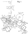
- the rewinder has a set of rollers for feeding the web material N, only one of which is visible in Fig. 1 and is indicated there by the number 1.
- the web material typically paper in one or more plies, is fed at high speed (of the order of 400-1000 m/min.) through a perforating unit, indicated in a general way by 5, comprising (in the illustrated example) a fixed support 7 and a rotating cylinder 9.
- the fixed support carries a counter-blade 11 interacting with a plurality of blades 13 carried by the rotating cylinder 9.
- a first winding roller 15, around which the web material N is run, and a second winding roller 17 are disposed after the perforating unit 5.
- the two rollers 15 and 17 rotate in the same direction (anti-clockwise in the figures). They form a nip 19 through which the web material N is fed.
- the number 21 indicates a third roller rotating in the same direction as the rollers 15 and 17 and carried by an oscillating arm 23 hinged to the structure of the machine.
- An actuator 27 controls the oscillation of the arm 23 to permit the control of the growth of the log being wound in the machine.
- the winding rollers 15, 17 and 21 form the area where the winding of each individual log is completed according to the procedures described in the following text.
- a curved rolling surface 33 consisting of an oscillating cradle 35 formed from a plurality of parallel strips which form a comb-shaped structure, for the purposes stated below.
- the oscillating cradle 35 forms, together with the cylindrical surface of the first winding roller 15, a channel 39 into which the winding cores are inserted in succession.
- the oscillating cradle 35 is hinged at 37 to a moving unit 40 carried by a sliding block 41 whose position is adjustable along a guide 43 carried by a cross-piece 45 integral with the supporting structure of the machine.
- the oscillating cradle 35 is acted on elastically by an elastic member 47 which pushes the oscillating cradle 35 into a position in which it bears on a receiving element 49 forming the first entrance portion of the channel 39, and is provided with a damping element made of elastomeric or similar material.
- the receiving element 49 is integral with the moving unit 40 and forms the initial entrance portion of the surface 33.
- the radius of curvature of the entrance portion of the said surface is approximately equal to the radius of the first winding roller 15 plus the minimum diameter of the core, reduced by a few millimetres (approximately 2 to 5 mm) to ensure a sufficient forcing of the core against the winding roller 15 in any operating conditions.
- the oscillating cradle 35 and the rolling surface 33 do not extend as far as the nip 19, but are interrupted at a certain distance from it.
- the second winding roller 17 is associated with a linking surface 53 consisting of a plurality of parallel strips 55 spaced apart to form a comb-shaped structure similar to the structure of the oscillating cradle 35.
- the strips 55 forming the comb-shaped structure extend into annular channels 17A in the roller 17 so that the surface 53 formed by the strips 55 provides a continuous link to the cylindrical surface of the roller 17.
- the strips 55 forming the linking surface 53 are carried by a moving unit 57 which also carries the second winding roller 17.
- the moving unit 57 is integral with a sliding block 59 whose position is adjustable along a guide 61 which is integral with a cross-piece 63 carried by the fixed structure of the machine.
- the adjustment of the position of the sliding block 59 and consequently of the moving unit 57 changes the centre spacing of the winding rollers 15 and 17 and consequently the size of the nip 19 formed between them.
- a rotating element 71 carrying means 73 of interrupting the web material N, these means interacting with the cylindrical surface of the winding roller 15, is disposed under the strips 35 forming the rolling surface 33.
- the interrupting means 73 are in the form of pressers, buffers or elastic pressure members which press lightly on the surface of the roller 15 during the stage of interruption or tearing of the web material.
- other configurations are possible, for example with plain or serrated blades, continuous or discontinuous in the direction of the axis of the roller 15, which interact with channels or counter-blades in the cylindrical surface of the roller 15.
- the rotating element 71 rotates intermittently, in the clockwise direction in the example illustrated.
- the pressers 73 move along a theoretical cylindrical surface C which has a circular section and has its axis coinciding with the axis 71A of rotation of the element 71 and forming an approximate tangent to the cylindrical surface of the roller 15, or with a slight interference with the latter surface.
- the cores A are inserted into the channel 39 by means of a conveyor indicated in a general way by 77, comprising a flexible continuous member 79 carrying a plurality of pushers 81 and running around a pulley 83.
- a gluing device which applies an adhesive to each core in defined areas, particularly in annular areas.
- the cores A are discharged from the conveyor 77 on to a slide 85 whose lower end is fixed to or rests on the unit 40 to guide the cores towards the channel 39.
- An elastic retaining member 87 is disposed in front of the slide 85, and retains the core on the slide 85 in a position from which the core is pushed into the channel 39 at the appropriate time by a pusher 89 rotating intermittently about its own axis of rotation 89A.
- Fig. 1 shows the terminal stage of winding of a log L.
- the first winding roller 15, the second winding roller 17 and the third winding roller 21 rotate with the same peripheral speed, equal to the speed of the feed of the web material N.
- a new core A has been discharged from the conveyor 77 on to the slide 85 and is retained by the retaining member 87.
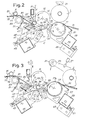
- Fig. 2 shows the start of the exchange operation, in other words the substitution of a new core for the log whose winding has been completed.
- the speed of the second winding roller 17 is decreased, and at the same time the rotating element 71 is made to rotate about the axis 71A and the pusher 89 is made to rotate about the axis 89A.
- This change of state has the following effects:
- the peripheral speed of the means 73 of interrupting the web material N is slightly lower than the speed of the feed of the web material, and therefore also slightly lower than the peripheral speed of the winding roller 15. Consequently, the web material N is torn at a point lying between the completed log L and the point of pinching between the means 73 and the roller 15. In this way a free edge of web material is generated and adheres to the core A, which in the meantime has begun to rotate in the channel 39 (Fig. 3).
- the operation described up to this point does not differ substantially from that illustrated in PCT/ IT94/00031.
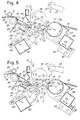
- the surface 33 formed by the oscillating cradle 35 has a curvature and position such that the channel 39 tapers from the entrance towards the nip 19.
- the capacity of the cradle 35 to oscillate with the yielding of the elastic member 47 enables the channel 39 to be adapted to the size of the core in transit. Variations in the diameter of the core are therefore compensated by a greater or lesser oscillation of the cradle 35, so that the rewinding machine can operate with cores of different diameters without requiring any intervention on the oscillating cradle 35.
- the linking surface 53 is positioned in such a way that when the core is at the final edge of the rolling surface 33 it can continue to roll continuously on to the linking surface 53 and from this to the second winding roller 17, as may be seen in the sequence illustrated in Figs. 4 and 5.
- the oscillating cradle 35 When the core A leaves the rolling surface 33, the oscillating cradle 35 is pushed by the elastic return member 47 into the position in which it bears on the damping members 49. These attenuate the impact and reduce to a minimum the noise and mechanical stress. It is possible to make the strips forming the oscillating cradle 35 of elastic material in such a way that it is the strips themselves that deform elastically to allow the core to pass.
- the term "oscillating cradle” includes a cradle made in this way, in other words one in which the oscillation is obtained by the elastic deformation of the members forming the cradle.
- Fig. 6 shows the intermediate state in which the log L in formation is in contact with the three rollers.
- the rotation of the rotating element 71 and the pusher 89 may stop at the same time, these stopping approximately in the angular positions shown in Fig. 1. They remain in this position until the start of a new exchange cycle on completion of the winding of the new log.
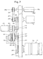
- Fig. 7 shows, for guidance, a section of a particularly advantageous embodiment of the control mechanisms for the above members.
- the number 173 indicates the side of the machine, on which are supported, together with other parts, the second winding roller 17, the rotating element 71 and the cylinder 89B (with the axis 89A) supporting the pusher 89.
- the number 175 indicates a motor which forms the actuator of the rotating element 71.
- a first toothed pulley 179 on which a toothed belt 181 runs and transmits the motion through a further pulley 183 to the rotating element 71, is keyed to the shaft 177 of the motor 175.
- a second toothed pulley 185 keyed to the shaft 177, transmits the motion through a toothed belt 187 to a toothed pulley 189.
- the pulley 189 is keyed to a first input axle of an epicyclic gear indicated in a general way by 191.
- the casing or spider of the epicyclic gear 191 is integral with a pulley 193 around which runs a belt 195 which takes the motion from a member of the machine, not shown, rotating at a speed proportional to the speed of the feed of the web material N.
- the said member may consist of any of the rollers for guiding and feeding the web material, for example the winding roller 15.
- the number 197 indicates the output axle of the epicyclic gear 191.
- a toothed pulley 199 which, through a toothed belt 201, transmits the motion to a toothed pulley 203 keyed to the shaft of the second winding roller 17, is keyed to the said output axle.
- a further pulley 205 which, through a belt 207, transmits the motion to a pulley 209 keyed on the shaft 89B of the pusher 89, is keyed to the shaft of the rotating element 71.
- the motor 175 In the stage of winding of the log L between the rollers 15, 17 and 21, the motor 175 is stationary. The winding roller 17 is made to rotate directly by the belt 195. The transmission ratio of the differential and of the pulleys used is such that a peripheral speed of the roller 17 equal to the peripheral speed of the roller 15 is obtained. When the winding of the log L is almost completed, the motor 175 is made to rotate.
- the oscillating cradle 35 does not have to be replaced, since it can be easily adapted to any core diameter.
- the adjustment of the position of the unit 40 enables the size of the entrance of the channel 39 to be adapted.
- a sliding block 59 whose position is adjustable and which carries the unit 57 supporting the winding roller 17 and the linking surface 53, it is possible to provide a system in which the position of the lower winding roller 17 is controlled by an electronic cam or by an electronically controlled actuator.
- the winding roller 17 may thus be moved even during each winding cycle, for example in order to change the size of the nip 19 during the transit of the core A.
- the adaptation to the diameters of the individual cores may be carried out by an intervention in the machine control program, possibly through the control panel.
- the adjustments of the unit 40 and the unit 57 may also be carried out rapidly and precisely by providing for example a system of adjustment with a threaded rod and an electronically controlled motor, as indicated schematically in Fig. 1. In this way the individual positions of the members of the machine may easily be changed from the control panel, using, if necessary, data stored for different core diameters.
- the movement of the adjustment of the unit 40 may advantageously take place in a direction F1 (Fig. 1) parallel to a plane passing through the line T1, containing the axis of the winding roller 15 and of the roller 89B supporting the pusher 89.
- the adjustment of the unit 57 takes place in a direction F2 parallel to a plane passing through the line T2 containing the axes of the two winding rollers 15 and 17.
- the size of the pusher 89 may be adjusted radially (for example by making it in two telescopically sliding parts which may be locked in any position with respect to each other), in such a way that it never interferes with the winding roller 15 but still securely grips the core, regardless of its diameter.
Landscapes
- Replacement Of Web Rolls (AREA)
- Winding Of Webs (AREA)
- Storage Of Web-Like Or Filamentary Materials (AREA)
- Basic Packing Technique (AREA)
- Rolls And Other Rotary Bodies (AREA)
- Packaging Of Special Articles (AREA)
- Insulators (AREA)
- Dowels (AREA)
- Reduction Rolling/Reduction Stand/Operation Of Reduction Machine (AREA)
- Battery Electrode And Active Subsutance (AREA)
- Fixed Capacitors And Capacitor Manufacturing Machines (AREA)
- Preliminary Treatment Of Fibers (AREA)
Applications Claiming Priority (3)
| Application Number | Priority Date | Filing Date | Title |
|---|---|---|---|
| ITFI940124 | 1994-06-16 | ||
| ITFI940124A IT1269116B (it) | 1994-06-16 | 1994-06-16 | Macchina ribobinatrice perfezionata per la formazione di rotoli di materiale nastriforme, adattabile a diversi diametri dell'anima di avvolgimento |
| PCT/IT1995/000098 WO1995034498A1 (en) | 1994-06-16 | 1995-06-07 | Web rewinding machine, adaptable to different core diameters |
Publications (2)
| Publication Number | Publication Date |
|---|---|
| EP0770028A1 EP0770028A1 (en) | 1997-05-02 |
| EP0770028B1 true EP0770028B1 (en) | 1999-09-08 |
Family
ID=11350934
Family Applications (1)
| Application Number | Title | Priority Date | Filing Date |
|---|---|---|---|
| EP95922711A Expired - Lifetime EP0770028B1 (en) | 1994-06-16 | 1995-06-07 | Web rewinding machine, adaptable to different core diameters |
Country Status (18)
| Country | Link |
|---|---|
| US (1) | US5769352A (es) |
| EP (1) | EP0770028B1 (es) |
| JP (1) | JP3587527B2 (es) |
| KR (1) | KR100202229B1 (es) |
| CN (1) | CN1063720C (es) |
| AT (1) | ATE184256T1 (es) |
| AU (1) | AU2751695A (es) |
| BR (1) | BR9508005A (es) |
| CA (1) | CA2192992C (es) |
| DE (1) | DE69512072T2 (es) |
| ES (1) | ES2136296T3 (es) |
| FI (1) | FI964955A7 (es) |
| GR (1) | GR3031635T3 (es) |
| IL (1) | IL114069A (es) |
| IT (1) | IT1269116B (es) |
| PL (1) | PL177066B1 (es) |
| RU (1) | RU2128617C1 (es) |
| WO (1) | WO1995034498A1 (es) |
Families Citing this family (64)
| Publication number | Priority date | Publication date | Assignee | Title |
|---|---|---|---|---|
| US6648266B1 (en) * | 1993-03-24 | 2003-11-18 | Fabio Perini S.P.A. | Rewinding machine and method for the formation of logs of web material with means for severing the web material |
| IT1286563B1 (it) * | 1996-03-05 | 1998-07-15 | Perini Fabio Spa | Macchina ribobinatrice incorporante un incollatore per i rotoli completati e relativo metodo di avvolgimento |
| DE19624716A1 (de) * | 1996-06-21 | 1996-11-21 | Voith Sulzer Papiermasch Gmbh | Wickelmaschine zum Aufwickeln einer laufenden Papierbahn |
| US5820064A (en) * | 1997-03-11 | 1998-10-13 | C.G. Bretting Manufacturing Company, Inc. | Winding control finger surface rewinder with core insert finger |
| US5772149A (en) * | 1996-09-18 | 1998-06-30 | C. G. Bretting Manufacturing Company, Inc. | Winding control finger surface rewinder |
| US6056229A (en) * | 1998-12-03 | 2000-05-02 | Paper Converting Machine Co. | Surface winder with pinch cutoff |
| IT1313815B1 (it) * | 1999-11-03 | 2002-09-23 | Giovanni Gambini | Dispositivo di introduzione di un'anima di avvolgimento in unamacchina ribobinatrice |
| US6372064B1 (en) * | 1999-12-13 | 2002-04-16 | C. G. Bretting Manufacturing Company, Inc. | Tail sealer apparatus and method |
| IT249984Y1 (it) * | 2000-12-27 | 2003-07-07 | Gambini Giovanni | Dispositivo di ribobinatura per formare un rotolo di carta in unamacchina ribobinatrice |
| US6595459B2 (en) | 2001-01-30 | 2003-07-22 | Kimberly-Clark Worldwide, Inc. | Apparatus and process for winding webbed material upon cores |
| ATE325766T1 (de) * | 2001-02-16 | 2006-06-15 | Mtc Macchine Trasformazione | Verfahren zum vorlegen von hülsen in einer wickelmaschine zum herstellen von rollen aus blattmaterial |
| ITMI20010306U1 (it) † | 2001-06-01 | 2002-12-02 | Gambini Giovanni | Dispositivo per la ribobinatura e la formazione di un rotolo di cartain una macchina ribobinatrice |
| US7406901B2 (en) * | 2001-12-20 | 2008-08-05 | Kimberly Clark Worldwide, Inc. | Auto sheet threading and cutting device and method |
| US6877689B2 (en) | 2002-09-27 | 2005-04-12 | C.G. Bretting Mfg. Co., Inc. | Rewinder apparatus and method |
| US7175127B2 (en) | 2002-09-27 | 2007-02-13 | C.G. Bretting Manufacturing Company, Inc. | Rewinder apparatus and method |
| ITFI20020227A1 (it) * | 2002-11-20 | 2004-05-21 | Perini Fabio Spa | Macchina ribobinatrice con un dispositivo incollatore per incollare il lembo finale del rotolo formato e relativo metodo di avvolgimento |
| DE60318487D1 (de) * | 2002-12-03 | 2008-02-14 | Perini Fabio Spa | Aufwickler zur herstellung von bahnmaterialrollen |
| ITFI20030311A1 (it) * | 2003-12-05 | 2005-06-06 | Perini Fabio Spa | Macchina ribobinatrice, metodo per la produzione di |
| EP1689661B1 (en) * | 2003-12-05 | 2008-02-27 | Fabio Perini S.p.A. | Method and machine for the production of logs of web material |
| ITFI20040061A1 (it) * | 2004-03-18 | 2004-06-18 | Perini Fabio Spa | Macchina ribobinatrice combinata periferica e centrale |
| US7210648B2 (en) * | 2004-09-28 | 2007-05-01 | Catalyst Paper Corporation | Disposable/reusable core adapters |
| US7222813B2 (en) * | 2005-03-16 | 2007-05-29 | Chan Li Machinery Co., Ltd. | Multiprocessing apparatus for forming logs of web material and log manufacture process |
| ITFI20050087A1 (it) * | 2005-05-02 | 2006-11-03 | Perini Fabio Spa | Metodo e dispositivo per produrre rotoli di materiale nastriforme con una fasciatura esterna |
| FR2886929B1 (fr) * | 2005-06-08 | 2007-09-14 | Georgia Pacific France Soc En | Rouleau avec moyen de maintien des spires |
| US7455260B2 (en) * | 2005-08-31 | 2008-11-25 | The Procter & Gamble Company | Process for winding a web material |
| US7392961B2 (en) * | 2005-08-31 | 2008-07-01 | The Procter & Gamble Company | Hybrid winder |
| US8800908B2 (en) * | 2005-11-04 | 2014-08-12 | The Procter & Gamble Company | Rewind system |
| US7546970B2 (en) * | 2005-11-04 | 2009-06-16 | The Procter & Gamble Company | Process for winding a web material |
| US8459586B2 (en) * | 2006-03-17 | 2013-06-11 | The Procter & Gamble Company | Process for rewinding a web material |
| US7559503B2 (en) * | 2006-03-17 | 2009-07-14 | The Procter & Gamble Company | Apparatus for rewinding web materials |
| CN101376468B (zh) * | 2007-08-28 | 2012-05-23 | 全利机械股份有限公司 | 具反向拨断机构的薄纸卷绕装置 |
| WO2009080890A1 (en) * | 2007-12-20 | 2009-07-02 | Metso Paper, Inc. | Reel and a method of reeling a fiber web |
| CN101497406B (zh) * | 2008-01-31 | 2011-12-28 | 全利机械股份有限公司 | 具预卷轮的薄纸卷绕及截断装置 |
| CN101423152B (zh) * | 2008-11-27 | 2010-06-09 | 丁戎江 | 一种包装带收卷机 |
| IT1392403B1 (it) * | 2008-12-23 | 2012-03-02 | Gambini Int Sa | Gruppo e metodo perfezionato di avvolgimento di carta attorno ad un'anima per realizzare un rotolo di carta |
| CN101891076B (zh) * | 2009-05-22 | 2013-05-29 | 金红叶纸业(苏州工业园区)有限公司 | 将纸张卷到卷芯上的复卷机及其方法 |
| US8157200B2 (en) * | 2009-07-24 | 2012-04-17 | The Procter & Gamble Company | Process for winding a web material |
| US8162251B2 (en) * | 2009-07-24 | 2012-04-24 | The Procter & Gamble Company | Hybrid winder |
| IT1398260B1 (it) * | 2010-02-23 | 2013-02-22 | Perini Fabio Spa | Macchina ribobinatrice e relativo metodo di avvolgimento. |
| CN101817460B (zh) * | 2010-04-27 | 2011-08-03 | 双钱集团(重庆)轮胎有限公司 | 重绕机 |
| US20130015228A1 (en) | 2011-07-15 | 2013-01-17 | Frank Stephen Hada | Method and Apparatus for Breaking a Web Using a Cut-off Assembly |
| ITFI20120142A1 (it) * | 2012-07-11 | 2014-01-12 | United Converting Srl | Macchina ribobinatrice |
| US9284147B2 (en) | 2012-09-21 | 2016-03-15 | Paper Converting Machine Company | Method and apparatus for producing coreless rolls of paper |
| ITMI20130953A1 (it) * | 2013-06-10 | 2014-12-11 | Gambini Int Sa | Gruppo e metodo di alimentazione di un'anima provvista di colla ad una ribobinatrice periferica e relativa ribobinatrice. |
| ITAR20130039A1 (it) * | 2013-09-27 | 2015-03-28 | Idea Pcm Srl | Macchina ribobinatrice del tipo perfezionata, particolarmente per la produzione di rotoli tissue e simili. |
| ITAR20130037A1 (it) * | 2013-09-27 | 2015-03-28 | Idea Pcm Srl | Macchina ribobinatrice del tipo perfezionata, particolarmente per la produzione di rotoli tissue e simili. |
| ITAR20130038A1 (it) * | 2013-09-27 | 2015-03-28 | Idea Pcm Srl | Macchina ribobinatrice del tipo perfezionata, particolarmente per la produzione di rotoli tissue e simili. |
| US20150307315A1 (en) | 2014-04-28 | 2015-10-29 | Paper Converting Machine Company Italia Spa | Flexible winding mandrel with core segments for producing rolls of wound paper |
| CN106715300B (zh) * | 2014-07-31 | 2019-03-05 | 法比奥·泼尼股份公司 | 用于生产幅材材料的卷筒的方法和复卷机 |
| ES2731338T3 (es) * | 2015-06-19 | 2019-11-15 | Futura Spa | Rebobinadora para la producción de bobinas de papel |
| US9809417B2 (en) | 2015-08-14 | 2017-11-07 | The Procter & Gamble Company | Surface winder |
| US10427902B2 (en) | 2016-03-04 | 2019-10-01 | The Procter & Gamble Company | Enhanced introductory portion for a surface winder |
| US10427903B2 (en) * | 2016-03-04 | 2019-10-01 | The Procter & Gamble Company | Leading edge device for a surface winder |
| US10442649B2 (en) * | 2016-03-04 | 2019-10-15 | The Procter & Gamble Company | Surface winder for producing logs of convolutely wound web materials |
| ES2940654T3 (es) | 2017-11-29 | 2023-05-10 | Paper Converting Machine Co | Rebobinadora de superficie con asistencia central y correa y tambor de enrollamiento que forman un nido de enrollamiento |
| EP3502022B1 (en) * | 2017-12-22 | 2020-09-16 | GAMBINI S.p.A. | Rewinding machine and relative method for rewinding and forming a roll of paper |
| CA3105935A1 (en) * | 2018-07-10 | 2020-01-16 | Maxima S.R.L. | Device for loading rolls on a machine and a machine comprising said device |
| DE102018008127B4 (de) | 2018-10-13 | 2022-06-09 | Hosokawa Alpine Aktiengesellschaft | Blaskopf und Verfahren zur Herstellung einer Mehrschichtschlauchfolie |
| US11247863B2 (en) | 2018-11-27 | 2022-02-15 | Paper Converting Machine Company | Flexible drive and core engagement members for a rewinding machine |
| DE102018009632B4 (de) | 2018-12-11 | 2021-12-09 | Hosokawa Alpine Aktiengesellschaft | Vorrichtung zum Aufwickeln und Wickelwechsel von bahnförmigem Material und ein Verfahren dafür |
| US11383946B2 (en) | 2019-05-13 | 2022-07-12 | Paper Converting Machine Company | Solid roll product formed from surface rewinder with belt and winding drum forming a winding nest |
| DE102020000334A1 (de) | 2020-01-21 | 2021-07-22 | Hosokawa Alpine Aktiengesellschaft | Vorrichtung und Verfahren zur monaxialen Längenänderung von Folienbahnen |
| IT202100019676A1 (it) * | 2021-07-23 | 2023-01-23 | Giotto Tech S R L | Macchina ribobinatrice e relativa culla di introduzione anime adattabile ad anime di diametri diversi |
| DE102022000351A1 (de) | 2022-01-29 | 2023-08-03 | Hosokawa Alpine Aktiengesellschaft | Verfahren und Vorrichtung zur Foliendickenregelung von gereckter im Folienblasverfahren hergestellter Schlauchfolie |
Family Cites Families (9)
| Publication number | Priority date | Publication date | Assignee | Title |
|---|---|---|---|---|
| IT1165998B (it) * | 1979-09-21 | 1987-04-29 | Fabio Perini | Dispositivo avvolgitore continuo per nastri di carta ed altro nella produzione di carta igienica e manufatti analoghi |
| DE3404225A1 (de) * | 1983-04-22 | 1984-10-25 | Paper Converting Machine Co., Green Bay, Wis. | Wickelvorrichtung |
| US4909452A (en) * | 1988-02-29 | 1990-03-20 | Paper Converting Machine Company | Surface winder and method |
| IT1233708B (it) * | 1989-07-11 | 1992-04-14 | Perini Navi Spa | Macchina ribobinatrice per la formazione di rotoli o bastoni, e metodo di avvolgimento |
| IT1246226B (it) * | 1991-01-09 | 1994-11-16 | Consani Alberto Spa | Perfezionamenti alle ribobinatrici per materiali in foglio |
| US5104055A (en) * | 1991-02-05 | 1992-04-14 | Paper Converting Machine Company | Apparatus and method for making convolutely wound logs |
| IT1240907B (it) * | 1991-07-16 | 1993-12-21 | Perini Fabio Spa | Metodo per la produzione di rotoli o logs di materiale nastriforme,e macchina per l'esecuzione di detto metodo |
| US5505405A (en) * | 1993-02-18 | 1996-04-09 | Paper Converting Machine Company | Surface rewinder and method having minimal drum to web slippage |
| US5421536A (en) * | 1993-07-19 | 1995-06-06 | Paper Coverting Machine Company | Surface winder with recycled mandrels and method |
-
1993
- 1993-06-07 RU RU97100738A patent/RU2128617C1/ru active
-
1994
- 1994-06-16 IT ITFI940124A patent/IT1269116B/it active IP Right Grant
-
1995
- 1995-06-07 CN CN95193598A patent/CN1063720C/zh not_active Expired - Fee Related
- 1995-06-07 US US08/750,286 patent/US5769352A/en not_active Expired - Lifetime
- 1995-06-07 EP EP95922711A patent/EP0770028B1/en not_active Expired - Lifetime
- 1995-06-07 DE DE69512072T patent/DE69512072T2/de not_active Expired - Lifetime
- 1995-06-07 ES ES95922711T patent/ES2136296T3/es not_active Expired - Lifetime
- 1995-06-07 JP JP50191196A patent/JP3587527B2/ja not_active Expired - Fee Related
- 1995-06-07 BR BR9508005A patent/BR9508005A/pt not_active IP Right Cessation
- 1995-06-07 AU AU27516/95A patent/AU2751695A/en not_active Abandoned
- 1995-06-07 PL PL95317756A patent/PL177066B1/pl not_active IP Right Cessation
- 1995-06-07 KR KR1019960707197A patent/KR100202229B1/ko not_active Expired - Fee Related
- 1995-06-07 CA CA002192992A patent/CA2192992C/en not_active Expired - Fee Related
- 1995-06-07 AT AT95922711T patent/ATE184256T1/de not_active IP Right Cessation
- 1995-06-07 WO PCT/IT1995/000098 patent/WO1995034498A1/en not_active Ceased
- 1995-06-08 IL IL11406995A patent/IL114069A/xx not_active IP Right Cessation
-
1996
- 1996-12-11 FI FI964955A patent/FI964955A7/fi unknown
-
1999
- 1999-10-27 GR GR990402724T patent/GR3031635T3/el unknown
Non-Patent Citations (1)
| Title |
|---|
| "Sincro: l'evoluzione del periferico", PERINI JOURNAL, no. 8, 1 February 1994 (1994-02-01), pages 04 - 07 * |
Also Published As
| Publication number | Publication date |
|---|---|
| PL317756A1 (en) | 1997-04-28 |
| DE69512072D1 (de) | 1999-10-14 |
| GR3031635T3 (en) | 2000-02-29 |
| EP0770028A1 (en) | 1997-05-02 |
| KR100202229B1 (ko) | 1999-06-15 |
| RU2128617C1 (ru) | 1999-04-10 |
| JP3587527B2 (ja) | 2004-11-10 |
| IL114069A0 (en) | 1995-10-31 |
| CA2192992A1 (en) | 1995-12-21 |
| ES2136296T3 (es) | 1999-11-16 |
| ITFI940124A1 (it) | 1995-12-16 |
| DE69512072T2 (de) | 2000-05-25 |
| CA2192992C (en) | 2000-04-25 |
| PL177066B1 (pl) | 1999-09-30 |
| WO1995034498A1 (en) | 1995-12-21 |
| FI964955A0 (fi) | 1996-12-11 |
| JPH10501786A (ja) | 1998-02-17 |
| IT1269116B (it) | 1997-03-21 |
| AU2751695A (en) | 1996-01-05 |
| ITFI940124A0 (it) | 1994-06-16 |
| FI964955A7 (fi) | 1996-12-11 |
| BR9508005A (pt) | 1997-11-18 |
| US5769352A (en) | 1998-06-23 |
| IL114069A (en) | 2000-02-17 |
| CN1150786A (zh) | 1997-05-28 |
| CN1063720C (zh) | 2001-03-28 |
| ATE184256T1 (de) | 1999-09-15 |
Similar Documents
| Publication | Publication Date | Title |
|---|---|---|
| EP0770028B1 (en) | Web rewinding machine, adaptable to different core diameters | |
| US5368252A (en) | Apparatus and method for winding rolls of web material with severing of web by roll acceleration | |
| US7318562B2 (en) | Rewinding machine and method for the formation of logs of web material with means for severing the web material | |
| US5979818A (en) | Rewinding machine and method for the formation of logs of web material with means for severing the web material | |
| US4962897A (en) | Web winding machine and method | |
| KR0163449B1 (ko) | 권취중의 로그를 지지하는 표면을 가진, 원단재료의 로그의 무코어권취용 개량권취기 | |
| EP0580561B1 (en) | Machine and method for the formation of coreless logs of web material | |
| EP2539259B1 (en) | Rewinding machine and method | |
| US5248106A (en) | Rewinder with means for changing the number of perforations provided around each log in the course of formation | |
| EP0199285A2 (en) | Web winding machine and method | |
| US5249756A (en) | Apparatus for changing the frequency of motion of a pusher | |
| EP3148906B1 (en) | Rewinding machine and rewinding method | |
| CA1322357C (en) | Web winding machine and method | |
| CA2100797C (en) | Machine and method for the formation of coreless logs of web material |
Legal Events
| Date | Code | Title | Description |
|---|---|---|---|
| PUAI | Public reference made under article 153(3) epc to a published international application that has entered the european phase |
Free format text: ORIGINAL CODE: 0009012 |
|
| 17P | Request for examination filed |
Effective date: 19961221 |
|
| AK | Designated contracting states |
Kind code of ref document: A1 Designated state(s): AT CH DE ES FR GB GR LI NL SE |
|
| 17Q | First examination report despatched |
Effective date: 19980211 |
|
| GRAG | Despatch of communication of intention to grant |
Free format text: ORIGINAL CODE: EPIDOS AGRA |
|
| GRAG | Despatch of communication of intention to grant |
Free format text: ORIGINAL CODE: EPIDOS AGRA |
|
| GRAH | Despatch of communication of intention to grant a patent |
Free format text: ORIGINAL CODE: EPIDOS IGRA |
|
| GRAH | Despatch of communication of intention to grant a patent |
Free format text: ORIGINAL CODE: EPIDOS IGRA |
|
| GRAA | (expected) grant |
Free format text: ORIGINAL CODE: 0009210 |
|
| AK | Designated contracting states |
Kind code of ref document: B1 Designated state(s): AT CH DE ES FR GB GR LI NL SE |
|
| REF | Corresponds to: |
Ref document number: 184256 Country of ref document: AT Date of ref document: 19990915 Kind code of ref document: T |
|
| REG | Reference to a national code |
Ref country code: CH Ref legal event code: NV Representative=s name: BOVARD AG PATENTANWAELTE Ref country code: CH Ref legal event code: EP |
|
| REF | Corresponds to: |
Ref document number: 69512072 Country of ref document: DE Date of ref document: 19991014 |
|
| REG | Reference to a national code |
Ref country code: ES Ref legal event code: FG2A Ref document number: 2136296 Country of ref document: ES Kind code of ref document: T3 |
|
| ET | Fr: translation filed | ||
| PGFP | Annual fee paid to national office [announced via postgrant information from national office to epo] |
Ref country code: SE Payment date: 20000517 Year of fee payment: 6 |
|
| PGFP | Annual fee paid to national office [announced via postgrant information from national office to epo] |
Ref country code: CH Payment date: 20000613 Year of fee payment: 6 |
|
| PGFP | Annual fee paid to national office [announced via postgrant information from national office to epo] |
Ref country code: GR Payment date: 20000616 Year of fee payment: 6 |
|
| PGFP | Annual fee paid to national office [announced via postgrant information from national office to epo] |
Ref country code: AT Payment date: 20000623 Year of fee payment: 6 |
|
| PGFP | Annual fee paid to national office [announced via postgrant information from national office to epo] |
Ref country code: NL Payment date: 20000630 Year of fee payment: 6 |
|
| PLBE | No opposition filed within time limit |
Free format text: ORIGINAL CODE: 0009261 |
|
| STAA | Information on the status of an ep patent application or granted ep patent |
Free format text: STATUS: NO OPPOSITION FILED WITHIN TIME LIMIT |
|
| 26N | No opposition filed | ||
| PG25 | Lapsed in a contracting state [announced via postgrant information from national office to epo] |
Ref country code: AT Free format text: LAPSE BECAUSE OF NON-PAYMENT OF DUE FEES Effective date: 20010607 |
|
| PG25 | Lapsed in a contracting state [announced via postgrant information from national office to epo] |
Ref country code: SE Free format text: LAPSE BECAUSE OF NON-PAYMENT OF DUE FEES Effective date: 20010608 |
|
| PG25 | Lapsed in a contracting state [announced via postgrant information from national office to epo] |
Ref country code: LI Free format text: LAPSE BECAUSE OF NON-PAYMENT OF DUE FEES Effective date: 20010630 Ref country code: CH Free format text: LAPSE BECAUSE OF NON-PAYMENT OF DUE FEES Effective date: 20010630 |
|
| PG25 | Lapsed in a contracting state [announced via postgrant information from national office to epo] |
Ref country code: GR Free format text: LAPSE BECAUSE OF NON-PAYMENT OF DUE FEES Effective date: 20011231 |
|
| PG25 | Lapsed in a contracting state [announced via postgrant information from national office to epo] |
Ref country code: NL Free format text: LAPSE BECAUSE OF NON-PAYMENT OF DUE FEES Effective date: 20020101 |
|
| REG | Reference to a national code |
Ref country code: GB Ref legal event code: IF02 |
|
| EUG | Se: european patent has lapsed |
Ref document number: 95922711.7 |
|
| REG | Reference to a national code |
Ref country code: CH Ref legal event code: PL |
|
| NLV4 | Nl: lapsed or anulled due to non-payment of the annual fee |
Effective date: 20020101 |
|
| PGFP | Annual fee paid to national office [announced via postgrant information from national office to epo] |
Ref country code: ES Payment date: 20120530 Year of fee payment: 18 |
|
| PGFP | Annual fee paid to national office [announced via postgrant information from national office to epo] |
Ref country code: GB Payment date: 20130605 Year of fee payment: 19 Ref country code: DE Payment date: 20130626 Year of fee payment: 19 |
|
| PGFP | Annual fee paid to national office [announced via postgrant information from national office to epo] |
Ref country code: FR Payment date: 20130726 Year of fee payment: 19 |
|
| REG | Reference to a national code |
Ref country code: DE Ref legal event code: R119 Ref document number: 69512072 Country of ref document: DE |
|
| GBPC | Gb: european patent ceased through non-payment of renewal fee |
Effective date: 20140607 |
|
| REG | Reference to a national code |
Ref country code: DE Ref legal event code: R119 Ref document number: 69512072 Country of ref document: DE Effective date: 20150101 |
|
| REG | Reference to a national code |
Ref country code: FR Ref legal event code: ST Effective date: 20150227 |
|
| PG25 | Lapsed in a contracting state [announced via postgrant information from national office to epo] |
Ref country code: DE Free format text: LAPSE BECAUSE OF NON-PAYMENT OF DUE FEES Effective date: 20150101 |
|
| PG25 | Lapsed in a contracting state [announced via postgrant information from national office to epo] |
Ref country code: FR Free format text: LAPSE BECAUSE OF NON-PAYMENT OF DUE FEES Effective date: 20140630 Ref country code: GB Free format text: LAPSE BECAUSE OF NON-PAYMENT OF DUE FEES Effective date: 20140607 |
|
| REG | Reference to a national code |
Ref country code: ES Ref legal event code: FD2A Effective date: 20150728 |
|
| PG25 | Lapsed in a contracting state [announced via postgrant information from national office to epo] |
Ref country code: ES Free format text: LAPSE BECAUSE OF NON-PAYMENT OF DUE FEES Effective date: 20140608 |