EP0769159B1 - Systeme de focalisation automatique pour microscopie a balayage - Google Patents
Systeme de focalisation automatique pour microscopie a balayage Download PDFInfo
- Publication number
- EP0769159B1 EP0769159B1 EP95925491A EP95925491A EP0769159B1 EP 0769159 B1 EP0769159 B1 EP 0769159B1 EP 95925491 A EP95925491 A EP 95925491A EP 95925491 A EP95925491 A EP 95925491A EP 0769159 B1 EP0769159 B1 EP 0769159B1
- Authority
- EP
- European Patent Office
- Prior art keywords
- focus
- weight
- autofocus
- averaged
- image
- Prior art date
- Legal status (The legal status is an assumption and is not a legal conclusion. Google has not performed a legal analysis and makes no representation as to the accuracy of the status listed.)
- Expired - Lifetime
Links
Images


Classifications
-
- G—PHYSICS
- G02—OPTICS
- G02B—OPTICAL ELEMENTS, SYSTEMS OR APPARATUS
- G02B21/00—Microscopes
- G02B21/24—Base structure
- G02B21/241—Devices for focusing
- G02B21/244—Devices for focusing using image analysis techniques
-
- G—PHYSICS
- G01—MEASURING; TESTING
- G01N—INVESTIGATING OR ANALYSING MATERIALS BY DETERMINING THEIR CHEMICAL OR PHYSICAL PROPERTIES
- G01N15/00—Investigating characteristics of particles; Investigating permeability, pore-volume, or surface-area of porous materials
- G01N15/10—Investigating individual particles
- G01N15/14—Electro-optical investigation, e.g. flow cytometers
- G01N15/1468—Electro-optical investigation, e.g. flow cytometers with spatial resolution of the texture or inner structure of the particle
- G01N15/147—Electro-optical investigation, e.g. flow cytometers with spatial resolution of the texture or inner structure of the particle the analysis being performed on a sample stream
-
- G—PHYSICS
- G01—MEASURING; TESTING
- G01N—INVESTIGATING OR ANALYSING MATERIALS BY DETERMINING THEIR CHEMICAL OR PHYSICAL PROPERTIES
- G01N21/00—Investigating or analysing materials by the use of optical means, i.e. using sub-millimetre waves, infrared, visible or ultraviolet light
- G01N21/62—Systems in which the material investigated is excited whereby it emits light or causes a change in wavelength of the incident light
- G01N21/63—Systems in which the material investigated is excited whereby it emits light or causes a change in wavelength of the incident light optically excited
- G01N21/64—Fluorescence; Phosphorescence
- G01N21/645—Specially adapted constructive features of fluorimeters
- G01N21/6456—Spatial resolved fluorescence measurements; Imaging
- G01N21/6458—Fluorescence microscopy
-
- G—PHYSICS
- G02—OPTICS
- G02B—OPTICAL ELEMENTS, SYSTEMS OR APPARATUS
- G02B21/00—Microscopes
- G02B21/0004—Microscopes specially adapted for specific applications
- G02B21/002—Scanning microscopes
Definitions
- the present invention relates to autofocusing and, more particularly, to a system for microscope autofocusing.
- Microscope slide surface irregularity is another source of error. Standard optical quality mirror flatness is about 1.5 ⁇ m over 25 mm. Given that mirrors are ground glass and microscope slides are float glass, microscope slide surface irregularity could be much greater. According to the definition by others, such as Frantig (Françon M: Progress in Microscopy. Row, Peterson, Evanston, I11., 1961), the theoretical microscope depth of field for an objective with numerical aperture (NA) 0.75 is 0.74 ⁇ m at a wavelength of 500 nm. Best focus can vary through a range of about 25 ⁇ m in a horizontal scan of 50 mm across a microscope slide. Whatever the source of instability, autofocus can compensate given that the positional variations have relatively long time constants.
- Position sensing methods such as interferometry, require independent calibration of the best focus location and, more importantly. a single well-defined surface from which to reflect light or sound. In light microscopy there are often two reflective surfaces, the coverslip and slide. In addition, tissue specimens can have significant depth and best focus is not necessarily achieved at the surface of the glass. These problems make absolute position sensing methods impractical for use in light microscopy.
- Image content analysis functions such as used by the present invention for autofocusing the microscope, on the other hand, depend only on characteristics measured directly from the image. Best focus is found by comparison of these characteristics in a series of images acquired at different vertical positions. This method of autofocus requires no independent reference and is not affected significantly by the second reflective surface. Its most important limitation is speed, which is dependent on the video rate, the vertical repositioning time, function calculation time and search range.
- Image content autofocus functions have previously been compared for brightfield microscopy, but apparently not for fluorescence or phase-contrast microscopy.
- Groen, Young and Ligthart (Groen FCA, Young IT, Ligthart G: A comparison of different focus functions for use in autofocus algorithms. Cytometry 6:81-91, 1985) compared 11 autofocus functions under brightfield using an electron microscope grid and a metaphase spread
- Vollath (Vollath D: Automatic Focusing by Correlative Methods. J Microsc 147:279-288, 1987) tested an autocorrelation function under brightfield using a pearlitic steel specimen.
- Groen et al. concluded that three autofocus functions, i.e., two gradient functions and the intensity variance, performed the best. However, some autofocus functions that performed well on one specimen did not perform well on others and the authors cautioned against extrapolating the results to other imaging modes and specimens.
- the signal is weak and antiphotobleaching agents cannot be used because of toxicity, the signal could easily be completely lost in the 5 - 10 video frames of exposure required for autofocus.
- the fluorescence byproducts themselves are toxic, and excessive exposure could alter the results or damage living cells. Therefore it is desirable to find a nondestructive imaging technique for autofocus.
- With brightfield microscopy fluorescent stained cells appear unstained, showing very little contrast.
- Phase-contrast microscopy gives high contrast images of unstained cells and is more useful for autofocus. For these reasons, auto focus function performance was tested for both phase contrast and fluorescence microscopy. More details of different approaches for autofocus can be found in the doctoral dissertation of Jeffrey H. Price entitled Scanning Cytometry for Cell Monolayers, University of California, San Diego, 1990.
- the present solution to the problem of fast and reliable autofocus of cellular components from photosensitive specimens and live cells in a system capable of scanning multiple microscope fields is the instant autofocus system and method as defined in claims 1 and 8, respectively, for scanning microscopy designed to automate, simplify, accelerate, and improve the quality of the process.
- the goal of the autofocus system is to accurately and automatically position the focus positioner, or focus mechanism, of the microscope so as to gather information and present it for further processing.
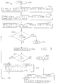
- Figure 1 illustrates the presently preferred embodiment of an autofocus system 100 of the present invention which uses vertical positioning to acquire focus information.
- the hardware components of the system 100 include an epifluorescent microscope 102, a motorized stage 103, controlled by a pair of XY motors 104a and a Z motor 104b, XYZ stage controller 106, a piezoelectric positioner 107, a video camera 108, an image processor 110, and a host processor 112. These components are further described below.
- the cells are imaged on a Nikon Optiphot 102 ( Figure 1) through a CF Fluor DL 20x C, 0.75 NA objective with Ph3 phase contrast.
- This fluorite objective provides high UV transmission.
- the epifluorescence filter cube has a 365 nm ⁇ 10 nm (50% of peak) bandpass excitation filter, a 400 nm dichroic mirror and no barrier filter.
- the images were further magnified through a Nikon CCTV 0.9 - 2.25 zoom lens onto a Dage VE 1000 RS-170 CCD camera 108. Experiments were performed at a zoom of 1.0 except for the sampling experiments, which were carried out at a series of magnifications.
- a Nikon 0.52 NA long working distance condenser is used for phase contrast.
- the microscope stage 103 ( Figure 1) is moved laterally under computer control by stepper motors.
- the stage 103 is built by Syn-Optics (Sunnyvale, CA) and modified by New England affiliated Technologies (Lawrence, MA) for finer stepping and simpler computer control.
- the smallest step size is 0.127 ⁇ m.
- the stage 103 is controlled by a New England affiliated Technologies 103M microstepping driver and an Oregon Micro Systems, Inc. (Beaverton, OR) PCX AT ISA-bus compatible computer board.
- Focus is changed with a piezoelectric objective positioner ("PIFOC") 107 and an E-810.10 closed loop controller (Polytech PI, Costa Mesa, CA).
- the piezo positioner 107 is sandwiched between the objective turret and the objective of the microscope 102.
- Measurements with an oscilloscope reading the built-in linear variable differential transformer (LVDT) sensor output showed that movements of ⁇ 1 ⁇ m occurred in ⁇ 10 milliseconds (ms) with the fluorite objective, and response was dependent on objective mass.
- LVDT linear variable differential transformer
- the 13 mm thick objective positioner significantly reduces image quality if this is not done, but movement through the 100 ⁇ m (0.004") range does not measurably degrade the image.
- Position is controlled by output from a digital-to-analog converter in a Keithley Metrabyte (Taunton, MA) DAS-1600 Data Acquisition Board.
- the 12-bit D/A converter divides the 100 ⁇ m range of the PIFOC 107 into 4096 steps of 24 nm each. Due to the previously discussed temperature and mechanical instabilities of the microscope 102 itself, actual focus accuracy is not better than a few microns over long periods, but for the required focus interval of a fraction of a second, the precision approaches the minimum step size.
- the fluorescence lamp is an Osram 100w HBO W/2 mercury vapor arc lamp in a Nikon HMX-2 lamp house. Variability of ⁇ ⁇ 3% over 3 hours with this lamp is measured by illumination of the cell stain solution described above, modified by an addition of 10 ⁇ g/ml DAPI and 1 mg/ml Herring Sperm DNA (Sigma, St. Louis). This solution is placed in an acrylic well under a sealed coverslip.
- phase contrast exposure is controlled with an EG&G Electro-Optics PS 450AC Power Supply (Salem, MA) and an XSA 80-35S-30171 xenon flash lamp (Advanced Radiation Corp., Santa Clara, CA).
- a Nikon HMX-2 lamp house was modified to house the xenon flash lamp and wired to the 450AC power supply.
- the strobe is triggered by the timer circuit on the data acquisition board.
- the timing for the strobe is supplied by a vertical blank hardware interrupt from the image processor 110 ( Figure 1).
- the data acquisition board has a programmable strobe delay that is set for 14 ms to assure that the objective positioner has completed movement prior to image acquisition.
- the strobe rate is 60 Hertz (Hz) during phase contrast focus testing.
- the average stability of this lamp is better than the mercury vapor arc lamp, but there are occasional intensity spikes.
- the focus position has to be moved in less than 16 ms (for 60 Hz operation), or the position has to be moved at a constant velocity and the image frozen with a strobe.
- the image is collected after movement has been completed. This is done in phase contrast by delaying the strobe 14 ms after the vertical blank in the video signal (when the command to change position is sent to the PIFOC 107). This delay insures that the focus position has changed before the image is collected by the video camera 108.
- the 14 ms delay and the strobe would not be required if the position could be changed during the vertical blank interval of about one ms.
- Better feedback control electronics on the PIFOC 107 would allow movement to occur fast enough to eliminate the need for the strobe.
- FIG. 1 An Imaging Technology, Inc. Series 151 Image Processor 110 ( Figure 1) is used for speeding image operations.
- a block diagram of the preferred image processor 110 is illustrated in Figure 3. It should be observed that while an image processor 110 will generally speed up the autofocus operation of the present invention, if speed is not critical there is no reason why the calculations performed therein could not take place in the host processor 112 ( Figure 1) or any other computer.
- the image processor 110 is preferably configured with six functional units, or boards, as follows: 1) a 512 x 512 8-bit Variable Scan Interface 130 for analog to digital conversion of the video signal generated by the camera 108, 2) a 512 x 512 x 32-bit Frame Buffer 132 for storage of four digital images, 3) a 1024 x 1024 x 32-bit Frame Buffer (not shown, but similar connections are made to the buses of the processor 110 as shown for the frame buffer 132) for storage of sixteen digital images, 4) a Histogram/Feature Extractor 134 for creating a 10-bit intensity histogram, 5) a Real Time Modular Processor (RTMP) 138 with a Real Time Sobel module for 8 x 8 convolutions and a 16-bit look-up-table, and 6) an Arithmetic/Logic Unit 136 for multiplication, subtraction, addition and scaling.
- RTMP Real Time Modular Processor
- the RTMP 138 is a single board with three plug-in connections for sub-modules.
- the Real Time Sobel module utilizes two of these connections and the look-up-table utilizes the third connection. All of these operations proceed at video rates and can be pipelined for parallel operation.
- the key components of this system for testing the autofocus functions are the 8 x 8 convolver (part of RTMP 138) and the histogrammer 134.
- the image is convolved and then histogrammed in a single pipelined video frame or field.
- the histogram is used to calculate the intensity sum, sum of squares and statistics, e.g., variance or standard deviation, with filtered image results truncated to 8 or 10 bits/pixel.
- the calculation results are further used to calculate a measure of focus.
- the image is first transferred to the host computer. Small differences are sometimes observed between the 8-bit and 10-bit results, but no further improvement is observed utilizing 16-bit results. Therefore, only 10-bit data for autofocus of selected fields is reported.
- the host computer 112 ( Figure 1) is preferably an AT-compatible 33 megaHertz (MHz) Intel i486 personal computer (PC).
- the software programs to implement the auto focus process ( Figure 4) and related control functions are written in 'C' and assembler.
- the C routines arc compiled with Metaware High C (Santa Cruz, CA).
- a Phar Lap (Cambridge, MA) assembler is used for the interrupt service routines that are running in the background. All object code is linked with the Phar Lap 386 DOS Extender.
- the Imaging Technology Series 151 C Library source code is also ported to ANSI C and recompiled with Metaware High C. This combination allows use of the full 32-bit capability of the i486 CPU by programs running under 16-bit DOS.
- Figure 2 represents a magnified image of a typical specimen comprising a set of cells, particularly cell nuclei, generally indicated at 116.
- NIH 3T3 cells were plated on washed, autoclaved #1.5 coverslips.
- the cells were maintained in Eagle's minimal essential medium with Earlc's salts, supplemented with 10% fetal bovine serum, 100 ⁇ g/ml gentamicin, and 0.26 mg/ml L-glutamine (final concentrations), in a humidified 5% CO 2 incubator at 37°C.
- the coverslips were washed in phosphate buffered saline (PBS), fixed for 10 minutes in 4% paraformaldehyde in 60% PBS. and stained for one hour.
- PBS phosphate buffered saline
- the stain solution consisted of 50 ng/ml 4',6-diamidino-2-phenylindole dihydrochloride (DAPI, Molecular Probes, Eugene, OR), 10 mM TRIS, 10 mM EDTA, 100 mM NaCl, and 2% 2-mercaptoethanol as described by others, such as Hamada and Fujita (Hamada S, Fujita S: DAPI Staining Improved for Quantitative Cytofluorometry. Histochem 79:219-226, 1983).
- DAPI 4',6-diamidino-2-phenylindole dihydrochloride
- the first three criteria - unimodality, accuracy and reproducibility - are most important for automated scanning.
- the range is less important because focus is usually performed on a field immediately adjacent to one where best focus was just calculated.
- Comparisons of microscope autofocus functions performed by Groen et al., loc. cit. led to the conclusion that the fifth criterion, general applicability for all types of images, cannot necessarily be expected. For a scanning system, however, it is sufficient to require applicability to one microscope imaging method (e.g., phase contrast or fluorescence) for all microscope fields.
- the seventh criterion, video signal compatibility, is hardware dependent and is easily satisfied.
- the eighth criterion, implementation is dependent on computer speed and function complexity.
- autofocus is controlled from the host processor 112 ( Figure 1).
- the host processor 112, or the image processor 110 under control of the host processor can perform a transformation on the image and obtain a value which represents a degree of focus. This value can then be compared with another value obtained from another image after the stage 103 is moved up or down via the XYZ stage controller 106 to indicate the next direction of stage movement or after the objective is adjusted by the PIFOC 107.
- the system 100 proceeds to a state 204 to acquire a digital image of the specimen 114 on the stage 103 at a first vertical position.
- the image is captured by the image processor 110.
- the system 100 applies a filter to the digital image to produce an intermediate or filtered image.
- the presently preferred embodiment utilizes a digital filter, and more specifically, the image sharpening transformation defined in function F 7 of Table 1. Of course, other filters, including analog filters can be used.
- the system 100 applies a measurement function to the intermediate image to obtain a magnitude.
- the presently preferred embodiment uses a contrast measurement function which utilizes the variance or standard deviation of image intensity, or the sum of the squares of the image intensity.
- the system 100 determines if the Nth image has been acquired.
- the value of N utilized varies according to the specific autofocus method employed. For the purposes of this discussion, and as an example, N will be equal to two. Therefore, during the first pass of states 204 to 210, only the first image is acquired, and the flow continues at state 212 wherein the stage 103 is moved by Z motor 104b in a vertical direction to a new (second) vertical position. In the preferred embodiment there are two focus mechanisms, therefore the piezoelectric PIFOC positioner 107 is moved instead of the stage 103 for fast autofocus, and both the PIFOC 107 and the stage 103 are to be moved together to combine fast autofocus and extended focus range.
- the flow continues at state 204, wherein a digital image is acquired at the second vertical position.
- the states 206 and 208 are executed again using the second image to obtain a second magnitude.
- the acquired magnitudes are compared and the focus is adjusted based on the results of the comparison.
- the focus mechanism 107 and the vertical stage stepper motor positioner are both focus positioners.
- the PIFOC is much faster, but has a shorter range (100 ⁇ m or 0.004" in the presently preferred model, 200 ⁇ m in an alternate embodiment.
- the stepper motor moving the entire mass of the stage, rather than just the objective, takes longer and cannot be use din a real time calculation, but has a range limited only by the room between the specimen and objective and the physical design of the microscope. Either or both can be used for autofocus.
- the stage For a slow system with focus in a few seconds, the stage is fast enough. For a fast system requiring focus in a fraction of a second, the PIFOC 107 is necessary. For applications requiring greater range and fast focus, the stage could be focused first and all subsequent focusing done by the PIFOC 107 until the range is exceeded. The stage could then be adjusted as necessary to keep the PIFOC 107 within its range. After the focus has been adjusted at state 214, the autofocus process 200 completes at an end state 216.
- a number of different autofocus functions may carry out one or both of states 206 and/or 208.
- Autofocus process 250 uses the well-known binary search algorithm to move the stage 103 ( Figure 1) and locate best focus.
- the search range is fixed as the distance of focus search interval and the center of the range is the center of focus search interval.
- Binary search autofocus is carried out by defining two focus positions between which focus is thought to exist and sequentially dividing the range in half to narrow down on best focus. The range is narrowed in this manner until it is smaller than the precision needed to identify best focus.
- the binary search autofocus process 250 begins at a start state 252, wherein a user, or an automated scanning program, requests focusing.
- the range is set to an initial value, e.g., 4 microns.
- the system 100 then moves to a state 254 wherein the focus mechanism is positioned at the center of the focus test range.
- the focus mechanism is the PIFOC 107 or the stage 103 (note the vertical control is 104b which moves the stage 103 through a series of gears inside the microscope), or both.
- An image is then acquired, filtered, and histogrammed by using the image processor 110. From the histogram, a single focus function result (Fc) is calculated for that position and stored.
- states 252 through 258 comprise an initialization sequence of the process. The rest of the flow chart states represents the loop that is executed to narrow the range until focus is found.
- a check is range less than minimum
- the minimum is user and application dependent. A practical example of the minimum is between 0.001 ⁇ m and 1.0 ⁇ m depending on the demands of the application.
- the minimum step size of the presently preferred PIFOC 107 is 0.024 ⁇ m and is determined by the digital/analog converter control board in the host computer 112 and the electronics of the PIFOC controller. If the range is small enough focus has been located, and the flow completes at an end state 272. If the range is not less than minimum, as determined at decision state 260, the system 100 continues at state 262 wherein the range is decreased by half.
- the new range will be defined by the old beginning and the center. If not, the focus is closer to the end of the range and the new range will be defined by the old center and end.
- the system moves to state 266, due to the focus value being closer to the beginning of the old range.
- the system 100 sets the new center to a position between the center and start of the old range, and moves the focus mechanism to the new center.
- the system also places the focus value (Fc) at the old center into the storage represented by Fb because this is the new end of the range.
- the system 100 further acquires, filters, histograms and calculates the focus function value for the new image and stores the result in Fc.
- the system 100 loops back to decision state 260 to determine if the range is now less than minimum, as previously described.
- Fa is not greater than Fb, as determined at decision state 264 and asserted at state 268, the system moves to state 270, due to the focus value being closer to the end of the old range.
- the system 100 sets the new center to a position between the old center and old end of the range, and moves the focus mechanism to the new center.
- the system also places the focus value at the old center (Fc) into the storage represented by Fa because this is the new start of the range.
- the system 100 further acquires, filters, histograms and calculates the focus function value for the new image and stores the result in Fc.
- the system 100 loops back to decision state 260, as previously described.
- the sequential autofocus process 300 begins at a start state 302, wherein a user, or an automated scanning program, requests focusing.
- the range is set to an initial value, e.g., 4 microns.
- the system 100 then moves to a state 304 wherein the start position is set to the initial value at the beginning of the range and the position number, n, is set to 0.
- the system 100 begins a loop (states 306 through 310) that positions the focus mechanism and calculates the focus function at each position.
- the focus mechanism is positioned to the 'start position plus (n times the step size)'.
- the step size is the same as the "focus increment" in the experimental table of Figure 12. Focus increments of 0.102, 0.195, 0.244, 0.146, 0.220 and 0.073 micrometers were used in those experiments. Then the image is acquired, filtered, histogrammed and the focus function calculated. The result is stored for later calculation of best focus. Proceeding to a decision state 308, the system 100 determines if 'the current position minus the start position ⁇ range', i.e., whether the focus position sequence finished. If so, the system moves to state 312 to calculate best focus. If not, the system 100 moves to state 310 to increment the position number, n, by one, and continue moving and calculating the focus function results by looping back to state 306.
- the system 100 moves to state 312 and computes the best focus.
- the power weighted average equation (Equation 1) is used to compute the best focus from the focus function values at positions 0 to z F 0 ...F z .
- the system advances to a decision state 314 to determine if the result lies too close to the beginning or end of the range.
- One example of too close is within 1/4 of the range. If the focus search range is 4 micrometers, and if the focus result were within 1 micrometer of either end of the range, then the center of the range would be repositioned and focus repeated. The actual value may vary depending on the application (specimen, required speed, etc.).
- the system 100 proceeds to state 316 to change the center to the end of the range closest to calculated focus and repeat the focus sequence by looping back to state 304, as previously described. Note that the range stays the same, but the process succeeds as long as the focus values increase toward best focus.
- the range can be broadened automatically to speed finding best focus. This feature is important in an application where the focus at an adjacent field is not known, such as for a commercial microscope focus attachment that focuses regardless of the start position. Best focus is achieved if the result is close to the center, as determined at decision state 314, and therefore the system 100 proceeds to state 318 wherein the focus mechanism is positioned at best focus.
- the sequential autofocus process 300 completes at an end state 320.
- One series of tests on the system 100 involved scanning areas of > 1000 microscope fields in a raster pattern automatically. At each new field the best focus for the previous field is used for the center of the test focus range. The microscope is refocused at the beginning of the test sequence on each field until the calculated best focus fell into the inner half of the test range. This allows best focus to be achieved even if the best focus is outside the initial test range. In practice, the test range was wide enough to make refocusing rare. Before autofocus, the intensity of the fluorescence image is summed to verify the presence of at least one cell. If no cells are present, the field is skipped. At the beginning of a new row, the best focus from the beginning of the previous row is the center of the test range.
- a specimen is placed on the microscope, the scanning rectangle chosen, and the corners of the rectangle checked to verify that the foci are within the 100 ⁇ m range.
- focus is performed manually. After the first field there is no human intervention until the scan is complete.
- Focus is calculated 20 times for both phase contrast and fluorescence on each field for statistical analysis of repeatability and comparison of accuracy. Precision is evaluated by the combined standard deviation of all focus trials from the entire scan. The combined standard deviation is computed by taking the square root of the average variance.
- Each focus test sequence is performed at 60 Hz by interrupt service routine control. An interrupt is initiated at the beginning of each vertical blank (60 Hz) by the Variable Scan Interface board on the Series 151 Image Processor. The interrupt service routine controls the strobe, and accounts for the 2 vertical blank delay between image integration on the CCD chip (objective positioner movement) and histogram acquisition on the image processor. Accounting for the delay between positioning and image stabilization enables repositioning and measurement to occur at video rates.
- the path through the image processor is from the digitized image in the Variable Scan Interface through the convolver to the histogrammer.
- the histogrammer input contains a 2-bank, 10-bit look-up table that is used to separate the odd and even fields for 60 Hz positioning and function calculation. Histogrammer look-up-table bank 0 is programmed to pass the even field unchanged and bank 1 is programmed to add 256 to the odd field.
- the interrupt service routine switches banks on alternate vertical blanks. At the end of each odd field the interrupt service routine transfers the resulting 9-bit histogram and independently calculates the odd and even sum, sum of squares and pixel count. These values are placed in arrays accessible to 'C' routines for final calculation of the best focus position.
- the function results are also normalized by the number of pixels.
- the maximum and the weighted average are used to find best focus. If the cells had been thinner than the depth of field of the microscope and the discrimination range of the focus function, the maximum would have been expected to perform well. In practice, however, the cells are thicker than the depth of field and much thicker than the discrimination range of the resolution functions (see Results section hereinbelow). Under these conditions, the function result is considered an estimate of the degree of focus at the corresponding position. A fit, or weighted average, of the data was performed during testing. Based on the ideal shape of the focus data, curve fits to a Gaussian and second and third order polynomials were tested.
- Sequential autofocus has an advantage over binary auto focus. Each focus position tested is defined before the focus routine begins. There is no dependence on the focus function value at previous positions. Therefore, delays, such as between integration of the image on the video camera 108 and digitization in the image processor 110, do not slow execution of the focus routine as much as they would with the binary search.
- the focus position In sequential autofocus, the focus position is moved to a series of locations, and at each location the image is acquired, filtered, and histogrammed. Based on the histogram, a single focus value is calculated and stored. When the focus test sequence is complete, a power-weighted average of the focus function values is used to calculate best focus. Unlike binary autofocus, the calculated best focus position may lie in-between the tested positions.
- Image content autofocus functions are based on the assumptions that images increase in contrast and resolution (edge sharpness) as focus improves.
- contrast model with an image that consists of light and dark regions, the light regions become darker and the dark regions become lighter as the equipment is moved farther from focus.
- This change in contrast can be described mathematically by the change in variance or standard deviation of pixel intensity.
- resolution model detail blurs as the image moves out of focus.
- Resolution can be measured by analyzing the Fourier frequency spectrum or by the application of gradient, or highpass filters that isolate the high frequencies. The magnitude of the high frequencies or gradients can then be used as a measure of resolution, which is defined as a maximum at best focus. The effects of the defocusing on the optical transfer function have been discussed by others.
- German Patent DE 2,910,875 C 2 U.S. Patent 4,350,884, 1982, European Patent 0017726
- the eleven autofocus functions that were tested are summarized in Table 1, along with references and calculation times on the computer hardware used here.
- the functions are divided into the following groups: 1) measures of resolution (F 1 - F 4 ), which are the sum of the squares of the result of a highpass filter; 2) measures of contrast (F 5 , F 6 ), represented by intensity variance or standard deviation, 3) combined measures of resolution and contrast (F 7 , F 8 ), and 4) autocorrelation functions (F 9 - F 11 ), which also incorporate components of resolution and/or contrast.
- measures of resolution F 1 - F 4
- measures of contrast F 5 , F 6
- F 7 , F 8 combined measures of resolution and contrast
- autocorrelation functions F 9 - F 11
- the image is represented by g i,j where i and j are the spatial coordinates and g is the pixel intensity and all sums are double over i and j.
- the dependence of the image and the autofocus function on vertical position is assumed (i.e., a function value is calculated from the image at each position).
- the tested autofocus functions were chosen based on evaluations by other investigators and available computer hardware. Functions such as the thresholded absolute gradient and the thresholded video-signal content by Mendelsohn and Mayall (Mendelsohn ML, Mayall BH: Computer-oriented analysis of human chromosomes-III focus. Comput Biol Med 2:137-150, 1972) were not tested because performance was shown by Groen et al., loc. cit., to depend in part on the arbitrary choice of a threshold. The entropy function, such as described by Shannon (Shannon CE: A mathematical theory of communications. Bell Sys Tech J 27:379-423, 623-656, 1948) was shown by Firestone et al.
- F 1 the squared gradient function described by others, such as Brenner et al. (Brenner JF, Dew BS, Horton JB, King T. Neurath PW, Selles WD: An automated microscope for cytologic research. J Histochem Cytochem 24:100-111, 1976), Erteza, loc. cit., and Muller and Buffington (Muller RA, Buffington A: Real-Time Correction of Atmospherically Degraded Telescope Images Through Image Sharpening. J Opt Soc Am 64:1200, 1974), is an implementation of the first derivative of the image intensity. In spectral terms, this is a bandpass filter that enhances frequencies just below the highest in the image. Squaring the sum magnifies the differences between function values.
- F 2 is the 1D Laplacian also described by Erteza, loc. cit., and Muller and Buffington, loc. cit. This filter is a measure of the second derivative of the image intensity. By operating on immediately adjacent pixels, F 2 has more predominant highpass frequency characteristics than F 1 , measuring resolution at a smaller scale. A variation of the Laplacian, based on lateral inhibition in the eye, was also evaluated by others, such as Harms and Aus (Harms H, Aus HM: Comparison of digital focus criteria for a TV microscope system. Cytometry 5:236-243, 1984).
- F 3 is the sum of the squares of the difference filter as described by Erteza, loc. cit., and Muller and Buffington, loc. cit.
- F 3 has the most predominant highpass frequency characteristics and measures resolution at the smallest scale.
- Similar derivative filters is explored by others, such as Shazeer and Harris (Shazeer D, Harris M: Digital Autofocus Using Scene Content, in Architectures and Algorithms for Digital Image Processing II, SPIE 534:150-158, 1985).
- F 4 a common 2D Laplacian not previously tested, was added for comparison. With square pixels, F 4 would have been a mixture of the highest frequencies. corresponding to the horizontally and vertically adjacent pixels, and the next highest frequencies, corresponding to the diagonally adjacent pixels. With the rectangular pixels and larger vertical sampling period of the RS-170 camera, however, this filter mixed in lower frequencies and did not have a higher frequency response than F 3 .
- F 5 the statistical variance of the intensity as a measure of contrast, was proposed by, for example, the Kernabas scholar Düsseldorf GmbH (Kernabas scholar Düsseldorf GmbH: Maschinen und strig Kunststoff Kunststoff Kunststoff Kunststoff Kunststoffificifs effet für Patent Specification PLA 7907 Düsseldorf, 1979).
- F 6 is the standard deviation of the intensity, or the square root of F 5 . It should be noted that under some conditions contrast achieves a local minimum, rather than a maximum, at best focus. The interference fringes that cause this are more commonly observed in transmission electron microscopy. With the light microscope, one way to observe this phenomenon is by using phase contrast to image a micrometer (e.g., 0.85 NA 40x objective and 10 ⁇ m spacing). Best focus is at a local contrast minimum, and interference produces a series of contrast maxima and minima as focus is changed. Thus, contrast as a measure of focus must be utilized with caution in specimens with nonrandom spacing viewed in brightfield microscope modes.
- F 7 and F 8 combine the variance and standard deviation, respectively, and a 3 x 3 sharpening filter.
- the frequency spectrum is independent of the variance. That is, the variance can be changed by scaling the intensities without altering the relative Fourier power spectrum.
- filtering the image can change the contrast.
- the image statistics measure a property fundamentally different from the Fourier spectrum, or sharpness of the image. This suggested using the variance (or standard deviation) as the basic autofocus measure and modifying the frequency effect by prefiltering the image.
- Correlation can be used to align images by multiplying them at different relative shifts and summing the resulting pixels. A maximum occurs when the images are correctly aligned.
- These correlation functions apparently have not been previously tested on biologic microscope images.
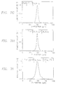
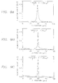
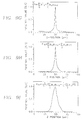
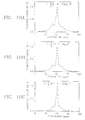
- Table 2 summarizes the peak widths and best focus of each function for fluorescence.
- the widths at 90% of maximum show a clear dependence on the frequency characteristics of the function.
- Functions F 1 , F 2 and F 3 are ordered from lowest to highest frequency enhancement and the peak widths narrow with higher frequency, giving F 3 the narrowest peak.
- F 9 which looks similar to F 2 in spatial filter terms, also has very similar 50% and 90% widths.
- the resolution functions have very narrow peaks, whereas the contrast functions have much wider peaks.
- the combination functions, F 7 and F 8 offer a trade off, with narrower peaks than the contrast functions and wider ranges than the resolution functions.
- the maxima, or best foci, for the predominantly statistical functions, F 5 , F 6 and F 11 differ by 1.07 ⁇ m from the others.
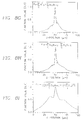
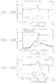
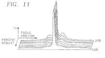
- the data for phase contrast focus on a single cell suggested that the frequency response of the focus function plays an important role in the formation of side peaks. It is likely that these side peaks arise from interference just above and just below best focus. Interference would be expected occur at lower frequencies since the departure from best focus degrades the modulation transfer function (MTF) of the microscope creating a lower frequency cut off. If a focus function measured only the highest frequencies it should be immune from these effects.
- the focus function is only one source of the frequency response.
- the microscope and the camera also have characteristic frequency responses that act prior to the focus function. Ideally, the camera should sample with at least twice the maximum frequency of the optical signal, according to the Nyquist sampling criterion.
- phase contrast and fluorescence autofocus were tested in a series of experiments scanning rectangular areas of > 1000 fields.
- the purpose of these experiments was to test the hypothesis that the weighted average is a good estimate of best focus, measure autofocus precision, determine how small a number of focus positions could be used without compromising precision in an attempt to achieve maximum speed, and compare the best focus between phase contrast and fluorescence.
- F 3 gave a narrow enough range with a single cell (1.03 ⁇ m 50% peak width from Table 5) to be a problem even for scanning microscopy. Therefore, F 7 and F 3 were considered good candidates. Since the real-time implementation utilized the interlaced camera signal, the variation of F 7 substituting a 1D sharpening filter for the 2D filter was used.
- phase contrast the image was strobed near the end of the video field after the piezoelectric focus had stopped at its new position, whereas in fluorescence, each field was integrating on the CCD while focus was changing (30 - 50% of the field duration). Also, as previously discussed, the cellular and nuclear components may have been distributed differently.
- the power-weighted average is the average of the positions, each weighted by a power of the focus value at that position.
- the weighted average is calculated from the array of focus function results.
- Each focus function result is a magnitude resulting from calculation of the function over the entire image frame (245,760 pixels) or field (122,880 pixels) at a single position. The maximum does not account for the magnitude of the values at adjacent positions, while the weighted average does by averaging the function values at all positions.
- the level of autofocus reliability and speed achieved here is an important step in bringing measurements common in flow cytometry closer to practical use in scanning cytometry. Such measurements may have advantages related to in situ analyses, such as morphology, relationship and position not possible with flow cytometry. Position may be a particular advantage for time lapse analysis of living cells where cell-by-cell tracking would be possible with short scan intervals.
Claims (12)
- Procédé pour mettre au point automatiquement un microscope (102), comportant un mécanisme de mise au point, en balayant un spécimen positionné sur une platine (103) du microscope, et en procédant à l'acquisition (204) d'une image numérique du spécimen au niveau de chacune des positions d'une pluralité de positions verticales, suivant un axe Z, consistant à :caractérisé en ce qu'il consiste à répéter les étapes (i) à (iii) pour chacune des positions verticales de la pluralité de positions verticales,(i) appliquer (206) un filtre numérique à une image numérique acquise au niveau de la position verticale, afin d'obtenir une image filtrée,(ii) appliquer (208) une fonction de mesure à l'image filtrée, afin d'obtenir une valeur représentant un degré de mise au point,(iii) appliquer (214, 312) une pondération à la valeur représentant un degré de mise au point, afin d'obtenir une valeur pondérée,appliquer (214, 312) une fonction de calcul de moyenne pondérée non-itérative aux valeurs de la pluralité de valeurs pondérées obtenues à l'étape (iii), afin d'obtenir une position de mise au point calculée par moyenne pondérée, etprovoquer le déplacement (214, 318) de la platine du microscope vers une position verticale correspondant à la position de mise au point calculée par moyenne pondérée.
- Procédé selon la revendication 1, dans lequel la fonction de calcul de moyenne pondérée correspond à :où :
 Wa est la position de mise au point calculée par moyenne pondérée,z est une position verticale de la pluralité de positions verticales,Fz est une valeur représentant un degré de mise au point au niveau de la position verticale, etn est une puissance de pondération.
 - Procédé selon la revendication 2, dans lequel les positions de la pluralité de positions verticales constituent une plage de recherche.
- Procédé selon la revendication 3, dans lequel la plage possède des incréments qui correspondent aux positions de la pluralité de positions verticales, chaque incrément étant inférieur à une profondeur de champ du microscope.
- Procédé selon la revendication 4, dans lequel l'application d'une fonction non-itérative s'effectue une première fois en établissant à une première valeur la puissance de pondération n afin d'obtenir une première position calculée par moyenne pondérée puis, une seconde fois, en établissant à une seconde valeur la puissance de pondération n afin d'obtenir une seconde position calculée par moyenne pondérée, et la position calculée par moyenne pondérée est obtenue en prenant la première position calculée par moyenne pondérée ou la seconde position calculée par moyenne pondérée.
- Procédé selon la revendication 1, dans lequel le filtre numérique effectue une accentuation.
- Procédé selon la revendication 1, dans lequel la fonction de mesure mesure le contraste et/ou la résolution.
- Dispositif de mise au point automatique pour microscope (102) comportant des moyens pour balayer un spécimen positionné sur une platine (103) de microscope, et des moyens pour procéder à l'acquisition d'une image numérique du spécimen au niveau de chacune des positions d'une pluralité de positions, suivant un axe Z, ledit dispositif comportantdes moyens adaptés pour appliquer un filtre numérique à une image numérique acquise au niveau de chaque position verticale de la pluralité de positions verticales, afin d'obtenir une image filtrée,des moyens adaptés pour appliquer une fonction de mesure et une pondération à ladite image filtrée, afin d'obtenir une pluralité de valeurs pondérées, chaque valeur pondérée représentant un degré de mise au point,des moyens adaptés pour appliquer une fonction de calcul de moyenne pondérée non-itérative aux valeurs de ladite pluralité de valeurs pondérées, afin d'obtenir une position de mise au point calculée par moyenne pondérée, etdes moyens pour provoquer le déplacement de la platine du microscope vers une position verticale correspondant à la position de mise au point.
- Dispositif selon la revendication 8, dans lequel la fonction de calcul de moyenne pondérée est :où :
 Wa est la position calculée par moyenne pondérée,z est une position verticale de la pluralité de positions verticales,Fz est une valeur représentant un degré de mise au point au niveau de la position verticale, etn est une puissance de pondération.
 - Dispositif selon la revendication 9, dans lequel les positions de la pluralité de positions verticales constituent une plage de recherche.
- Dispositif selon la revendication 10, dans lequel la plage possède des incréments qui correspondent aux positions de la pluralité de positions verticales, chaque incrément étant inférieur à une profondeur de champ du microscope.
- Dispositif selon la revendication 11, dans lequel les moyens pour appliquer la fonction non-itérative obtiennent tout d'abord une première position calculée par moyenne pondérée en établissant à une première valeur la puissance de pondération n, puis obtiennent une seconde position calculée par moyenne pondérée en établissant à une seconde valeur la puissance de pondération n, et la position de mise au point est obtenue en prenant la première position calculée par moyenne pondérée ou la seconde position calculée par moyenne pondérée.
Priority Applications (2)
| Application Number | Priority Date | Filing Date | Title |
|---|---|---|---|
| EP97120924A EP0834758B1 (fr) | 1994-07-01 | 1995-06-30 | Système d'image en volume continu pour microscopie à balayage |
| GR990402832T GR3031737T3 (en) | 1994-07-01 | 1999-11-03 | Autofocus system for scanning microscopy |
Applications Claiming Priority (3)
| Application Number | Priority Date | Filing Date | Title |
|---|---|---|---|
| US27001794A | 1994-07-01 | 1994-07-01 | |
| US270017 | 1994-07-01 | ||
| PCT/US1995/008424 WO1996001438A1 (fr) | 1994-07-01 | 1995-06-30 | Systeme de focalisation automatique pour microscopie a balayage |
Related Child Applications (1)
| Application Number | Title | Priority Date | Filing Date |
|---|---|---|---|
| EP97120924A Division EP0834758B1 (fr) | 1994-07-01 | 1995-06-30 | Système d'image en volume continu pour microscopie à balayage |
Publications (2)
| Publication Number | Publication Date |
|---|---|
| EP0769159A1 EP0769159A1 (fr) | 1997-04-23 |
| EP0769159B1 true EP0769159B1 (fr) | 1999-03-10 |
Family
ID=23029550
Family Applications (2)
| Application Number | Title | Priority Date | Filing Date |
|---|---|---|---|
| EP95925491A Expired - Lifetime EP0769159B1 (fr) | 1994-07-01 | 1995-06-30 | Systeme de focalisation automatique pour microscopie a balayage |
| EP97120924A Expired - Lifetime EP0834758B1 (fr) | 1994-07-01 | 1995-06-30 | Système d'image en volume continu pour microscopie à balayage |
Family Applications After (1)
| Application Number | Title | Priority Date | Filing Date |
|---|---|---|---|
| EP97120924A Expired - Lifetime EP0834758B1 (fr) | 1994-07-01 | 1995-06-30 | Système d'image en volume continu pour microscopie à balayage |
Country Status (11)
| Country | Link |
|---|---|
| EP (2) | EP0769159B1 (fr) |
| JP (1) | JPH10502466A (fr) |
| AT (2) | ATE177539T1 (fr) |
| AU (1) | AU2960395A (fr) |
| CA (1) | CA2192986C (fr) |
| DE (2) | DE69508248T2 (fr) |
| DK (2) | DK0769159T3 (fr) |
| ES (2) | ES2140178T3 (fr) |
| GR (1) | GR3031737T3 (fr) |
| MX (1) | MX9606683A (fr) |
| WO (1) | WO1996001438A1 (fr) |
Cited By (3)
| Publication number | Priority date | Publication date | Assignee | Title |
|---|---|---|---|---|
| US6970789B2 (en) | 2001-02-02 | 2005-11-29 | Cellomics, Inc. | Method of determining a best initial focal position estimate |
| DE102014104430A1 (de) | 2014-03-28 | 2015-10-01 | Jenoptik Optical Systems Gmbh | Objektiv mit axialem Verstellglied zur aktiven Verstellung von Objektivelementen |
| US9400377B2 (en) | 2009-09-29 | 2016-07-26 | Carl Zeiss Microscopy Gmbh | Automatic focusing method for an optical instrument for magnified viewing of an object |
Families Citing this family (57)
| Publication number | Priority date | Publication date | Assignee | Title |
|---|---|---|---|---|
| US6268611B1 (en) | 1997-12-18 | 2001-07-31 | Cellavision Ab | Feature-free registration of dissimilar images using a robust similarity metric |
| US6640014B1 (en) | 1999-01-22 | 2003-10-28 | Jeffrey H. Price | Automatic on-the-fly focusing for continuous image acquisition in high-resolution microscopy |
| US6743576B1 (en) | 1999-05-14 | 2004-06-01 | Cytokinetics, Inc. | Database system for predictive cellular bioinformatics |
| US7151847B2 (en) | 2001-02-20 | 2006-12-19 | Cytokinetics, Inc. | Image analysis of the golgi complex |
| US6651008B1 (en) | 1999-05-14 | 2003-11-18 | Cytokinetics, Inc. | Database system including computer code for predictive cellular bioinformatics |
| WO2000075709A1 (fr) * | 1999-06-04 | 2000-12-14 | Janssen Pharmaceutica N.V. | Systeme robuste de mise au point pour microscope |
| AU6603100A (en) * | 1999-08-10 | 2001-03-05 | Cellavision Ab | Methods and devices in an optical system |
| US6583865B2 (en) * | 2000-08-25 | 2003-06-24 | Amnis Corporation | Alternative detector configuration and mode of operation of a time delay integration particle analyzer |
| US6804385B2 (en) | 2000-10-24 | 2004-10-12 | Oncosis | Method and device for selectively targeting cells within a three-dimensional specimen |
| US7218764B2 (en) | 2000-12-04 | 2007-05-15 | Cytokinetics, Inc. | Ploidy classification method |
| US6956961B2 (en) | 2001-02-20 | 2005-10-18 | Cytokinetics, Inc. | Extracting shape information contained in cell images |
| US7016787B2 (en) | 2001-02-20 | 2006-03-21 | Cytokinetics, Inc. | Characterizing biological stimuli by response curves |
| DE10115309A1 (de) * | 2001-03-28 | 2002-10-02 | Gnothis Holding Sa Ecublens | Mikroskopanordnung zur Fluoreszenzspektorskopie, insbesondere Fluoreszenzkorrelationsspektroskopie |
| JP2005502907A (ja) | 2001-09-11 | 2005-01-27 | ライカ ミクロジュステムス ヴェツラー ゲーエムベーハー | 対象物の光学的検査をするための方法および装置 |
| DE10234404B4 (de) | 2002-07-29 | 2021-10-14 | Leica Microsystems Cms Gmbh | Verfahren, Anordnung und Software zur Überwachung und Kontrolle eines Mikroskops |
| DE10319182B4 (de) * | 2003-04-29 | 2008-06-12 | Carl Zeiss Jena Gmbh | Verfahren und Anordnung zur Bestimmung der Fokusposition bei der Abbildung einer Probe |
| DE10362244B4 (de) * | 2003-04-29 | 2014-06-26 | Carl Zeiss Microscopy Gmbh | Verfahren zur Bestimmung der Fokusposition und der Verkippung der Fokusebene bei der Abbildung einer Probe |
| EP1646926A2 (fr) | 2003-07-18 | 2006-04-19 | Cytokinetics, Inc. | Caracterisation de stimuli biologiques par courbes de reponse |
| US20050014217A1 (en) | 2003-07-18 | 2005-01-20 | Cytokinetics, Inc. | Predicting hepatotoxicity using cell based assays |
| US7235353B2 (en) | 2003-07-18 | 2007-06-26 | Cytokinetics, Inc. | Predicting hepatotoxicity using cell based assays |
| US8169534B2 (en) | 2004-02-24 | 2012-05-01 | The Invention Science Fund I, Llc | Volumetric imaging using “virtual” lenslets |
| US7232221B2 (en) | 2004-02-24 | 2007-06-19 | Searete, Llc | Volumetric imaging using “virtual” lenslets |
| EP1751599B1 (fr) * | 2004-05-27 | 2018-07-11 | Leica Biosystems Imaging, Inc. | Systeme et procede d'evaluation de la qualite d'image d'une diapositive virtuelle |
| US7323318B2 (en) | 2004-07-15 | 2008-01-29 | Cytokinetics, Inc. | Assay for distinguishing live and dead cells |
| US7417213B2 (en) | 2005-06-22 | 2008-08-26 | Tripath Imaging, Inc. | Apparatus and method for rapid microscopic image focusing having a movable objective |
| US20070031056A1 (en) | 2005-08-02 | 2007-02-08 | Perz Cynthia B | System for and method of focusing in automated microscope systems |
| EP2023127B1 (fr) | 2006-05-31 | 2017-12-20 | Olympus Corporation | Méthode et systéme d'imagerie pour specimens biologiques |
| DE102006055987B4 (de) * | 2006-11-24 | 2011-06-01 | Pentacon Gmbh Foto- Und Feinwerktechnik | Verfahren zur Fokussierung optischer Bilderfassungseinrichtungen |
| US11940413B2 (en) | 2007-02-05 | 2024-03-26 | IsoPlexis Corporation | Methods and devices for sequencing nucleic acids in smaller batches |
| US11035823B2 (en) | 2009-03-17 | 2021-06-15 | Qiagen Sciences, Llc | Methods and devices for sequencing nucleic acids in smaller batches |
| DE112008000363B4 (de) | 2007-02-05 | 2021-12-02 | Qiagen Sciences, LLC (n.d.Ges.d. Staates Delaware) | Vorrichtung zur Detektion und ihre Verwendung |
| US8481259B2 (en) | 2007-02-05 | 2013-07-09 | Intelligent Bio-Systems, Inc. | Methods and devices for sequencing nucleic acids in smaller batches |
| US20090185734A1 (en) * | 2008-01-18 | 2009-07-23 | Hemocue Ab | Apparatus and method for analysis of particles in a liquid sample |
| DE102008015885A1 (de) * | 2008-03-26 | 2009-10-01 | Synentec Gmbh | Vorrichtung und Verfahren zur Autofokussierung von optischen Geräten, insbesondere von Mikroskopen |
| US8774488B2 (en) | 2010-03-11 | 2014-07-08 | Cellscape Corporation | Method and device for identification of nucleated red blood cells from a maternal blood sample |
| US9578227B2 (en) | 2010-06-24 | 2017-02-21 | Koninklijke Philips N.V. | Determining a polar error signal of a focus position of an autofocus imaging system |
| US9522396B2 (en) | 2010-12-29 | 2016-12-20 | S.D. Sight Diagnostics Ltd. | Apparatus and method for automatic detection of pathogens |
| DE102011007751B4 (de) | 2011-04-20 | 2023-10-19 | Carl Zeiss Microscopy Gmbh | Weitfeldmikroskop und Verfahren zur Weitfeldmikroskopie |
| EP2715321A4 (fr) * | 2011-05-25 | 2014-10-29 | Huron Technologies Internat Inc | Scanner de diapositives pour pathologie 3d |
| US10640807B2 (en) | 2011-12-29 | 2020-05-05 | S.D. Sight Diagnostics Ltd | Methods and systems for detecting a pathogen in a biological sample |
| WO2014188405A1 (fr) | 2013-05-23 | 2014-11-27 | Parasight Ltd. | Procédé et système d'imagerie de prélèvement cellulaire |
| IL227276A0 (en) | 2013-07-01 | 2014-03-06 | Parasight Ltd | A method and system for obtaining a monolayer of cells, for use specifically for diagnosis |
| WO2015029032A1 (fr) * | 2013-08-26 | 2015-03-05 | Parasight Ltd. | Systèmes, procédés et produits programmes d'ordinateur de microscopie numérique |
| JP6219214B2 (ja) | 2014-03-31 | 2017-10-25 | 富士フイルム株式会社 | 細胞撮像制御装置および方法並びにプログラム |
| US10482595B2 (en) | 2014-08-27 | 2019-11-19 | S.D. Sight Diagnostics Ltd. | System and method for calculating focus variation for a digital microscope |
| EP3859425B1 (fr) | 2015-09-17 | 2024-04-17 | S.D. Sight Diagnostics Ltd. | Méthodes et appareil de détection d'entité dans un échantillon corporel |
| US9939623B2 (en) * | 2015-10-19 | 2018-04-10 | Molecular Devices, Llc | Microscope system with transillumination-based autofocusing for photoluminescence imaging |
| JP6578928B2 (ja) * | 2015-12-16 | 2019-09-25 | コニカミノルタ株式会社 | 蛍光画像の合焦位置特定システム、合焦位置特定方法および合焦位置特定プログラム |
| US11733150B2 (en) | 2016-03-30 | 2023-08-22 | S.D. Sight Diagnostics Ltd. | Distinguishing between blood sample components |
| EP3455610B1 (fr) | 2016-05-11 | 2023-01-04 | S.D. Sight Diagnostics Ltd. | Porte-échantillon pour mesures optiques |
| EP3455626A1 (fr) | 2016-05-11 | 2019-03-20 | S.D. Sight Diagnostics Ltd. | Conduite de mesures optiques sur un échantillon |
| KR20190139828A (ko) * | 2016-11-25 | 2019-12-18 | 텔레다인 달사 비.브이. | 복수의 엑스선 영상들로부터 2d 영상을 재구성하기 위한 방법 |
| EP3351992B1 (fr) * | 2017-01-24 | 2019-10-23 | Horiba France SAS | Procédé et système de mesure de micro-spectrométrie |
| EP3396430B1 (fr) | 2017-04-27 | 2023-08-16 | Euroimmun Medizinische Labordiagnostika AG | Agencement et procédé de balayage optique |
| US11921272B2 (en) | 2017-11-14 | 2024-03-05 | S.D. Sight Diagnostics Ltd. | Sample carrier for optical measurements |
| US11422349B2 (en) * | 2017-11-28 | 2022-08-23 | Leica Biosystems Imaging, Inc. | Dual processor image processing |
| GB2600996A (en) | 2020-11-17 | 2022-05-18 | Ffei Ltd | Image scanning apparatus and method |
Citations (1)
| Publication number | Priority date | Publication date | Assignee | Title |
|---|---|---|---|---|
| WO1996023240A1 (fr) * | 1995-01-27 | 1996-08-01 | Fraunhofer-Gesellschaft zur Förderung der angewandten Forschung e.V. | Procede et dispositif pour photographier un objet |
Family Cites Families (16)
| Publication number | Priority date | Publication date | Assignee | Title |
|---|---|---|---|---|
| JPS51112114A (en) * | 1975-03-27 | 1976-10-04 | Matsushita Electric Ind Co Ltd | Record reproduction method |
| DE2615841C3 (de) * | 1976-04-10 | 1978-10-19 | Fa. Carl Zeiss, 7920 Heidenheim | Verfahren zum automatischen Nachführen der Scharfeinstellung eines mit einer Fernsehkamera ausgerüsteten Mikroskops |
| JPS5635111A (en) * | 1979-08-31 | 1981-04-07 | Nippon Kogaku Kk <Nikon> | Focus detector of phase contrast microscope |
| US4342905A (en) * | 1979-08-31 | 1982-08-03 | Nippon Kogaku K.K. | Automatic focusing device of a microscope |
| DE3584314D1 (de) * | 1984-04-16 | 1991-11-14 | Image Recognition Systems Ltd | Automatische fokussiereinrichtung. |
| JPS61112114A (ja) * | 1984-11-06 | 1986-05-30 | Mitsubishi Rayon Co Ltd | 自動焦点調節方法 |
| JPS63127148A (ja) * | 1986-11-17 | 1988-05-31 | Kanzaki Paper Mfg Co Ltd | 表面検査装置 |
| JPS6454408A (en) * | 1987-08-25 | 1989-03-01 | Hitachi Ltd | Automatic focusing method |
| JPH0237313A (ja) * | 1988-07-27 | 1990-02-07 | Hitachi Ltd | 自動焦点位置検出方法 |
| DE3828381C2 (de) * | 1988-08-20 | 1997-09-11 | Zeiss Carl Fa | Verfahren und Einrichtung zur automatischen Fokussierung eines optischen Systems |
| JPH02276363A (ja) * | 1989-04-18 | 1990-11-13 | Canon Inc | 画像読取装置 |
| US5239178A (en) | 1990-11-10 | 1993-08-24 | Carl Zeiss | Optical device with an illuminating grid and detector grid arranged confocally to an object |
| JP3267984B2 (ja) * | 1991-04-17 | 2002-03-25 | 株式会社三協精機製作所 | 自動合焦装置及び自動合焦装置における合焦調整方法 |
| US5239170A (en) * | 1991-10-23 | 1993-08-24 | Karl Suss America, Incorporated | Autofocus method and apparatus for imaging microscopy using a predetermined visual imaging feature |
| JPH05210042A (ja) * | 1992-01-23 | 1993-08-20 | Asahi Optical Co Ltd | 自動焦点調節装置 |
| DE4226523B4 (de) * | 1992-08-11 | 2005-01-05 | Universität Stuttgart | Verfahren und Vorrichtung zum automatischen Fokussieren auf Objekte |
-
1995
- 1995-06-30 CA CA002192986A patent/CA2192986C/fr not_active Expired - Fee Related
- 1995-06-30 WO PCT/US1995/008424 patent/WO1996001438A1/fr active IP Right Grant
- 1995-06-30 AU AU29603/95A patent/AU2960395A/en not_active Abandoned
- 1995-06-30 MX MX9606683A patent/MX9606683A/es not_active IP Right Cessation
- 1995-06-30 DE DE69508248T patent/DE69508248T2/de not_active Expired - Lifetime
- 1995-06-30 ES ES97120924T patent/ES2140178T3/es not_active Expired - Lifetime
- 1995-06-30 JP JP8503973A patent/JPH10502466A/ja active Pending
- 1995-06-30 AT AT95925491T patent/ATE177539T1/de not_active IP Right Cessation
- 1995-06-30 ES ES95925491T patent/ES2131838T3/es not_active Expired - Lifetime
- 1995-06-30 AT AT97120924T patent/ATE184113T1/de not_active IP Right Cessation
- 1995-06-30 EP EP95925491A patent/EP0769159B1/fr not_active Expired - Lifetime
- 1995-06-30 DE DE69511903T patent/DE69511903T2/de not_active Expired - Fee Related
- 1995-06-30 EP EP97120924A patent/EP0834758B1/fr not_active Expired - Lifetime
- 1995-06-30 DK DK95925491T patent/DK0769159T3/da active
- 1995-06-30 DK DK97120924T patent/DK0834758T3/da active
-
1999
- 1999-11-03 GR GR990402832T patent/GR3031737T3/el unknown
Patent Citations (1)
| Publication number | Priority date | Publication date | Assignee | Title |
|---|---|---|---|---|
| WO1996023240A1 (fr) * | 1995-01-27 | 1996-08-01 | Fraunhofer-Gesellschaft zur Förderung der angewandten Forschung e.V. | Procede et dispositif pour photographier un objet |
Cited By (4)
| Publication number | Priority date | Publication date | Assignee | Title |
|---|---|---|---|---|
| US6970789B2 (en) | 2001-02-02 | 2005-11-29 | Cellomics, Inc. | Method of determining a best initial focal position estimate |
| US9400377B2 (en) | 2009-09-29 | 2016-07-26 | Carl Zeiss Microscopy Gmbh | Automatic focusing method for an optical instrument for magnified viewing of an object |
| DE102014104430A1 (de) | 2014-03-28 | 2015-10-01 | Jenoptik Optical Systems Gmbh | Objektiv mit axialem Verstellglied zur aktiven Verstellung von Objektivelementen |
| DE102014104430B4 (de) * | 2014-03-28 | 2015-10-29 | Jenoptik Optical Systems Gmbh | Objektiv mit axialem Verstellglied zur aktiven Verstellung von Objektivelementen |
Also Published As
| Publication number | Publication date |
|---|---|
| DE69511903T2 (de) | 2000-04-20 |
| MX9606683A (es) | 1997-12-31 |
| WO1996001438A1 (fr) | 1996-01-18 |
| EP0834758A3 (fr) | 1998-05-06 |
| DE69511903D1 (de) | 1999-10-07 |
| EP0834758B1 (fr) | 1999-09-01 |
| EP0834758A2 (fr) | 1998-04-08 |
| AU2960395A (en) | 1996-01-25 |
| DE69508248D1 (de) | 1999-04-15 |
| CA2192986A1 (fr) | 1996-01-18 |
| ES2131838T3 (es) | 1999-08-01 |
| GR3031737T3 (en) | 2000-02-29 |
| JPH10502466A (ja) | 1998-03-03 |
| ES2140178T3 (es) | 2000-02-16 |
| DK0769159T3 (da) | 1999-09-27 |
| ATE184113T1 (de) | 1999-09-15 |
| DE69508248T2 (de) | 1999-11-04 |
| EP0769159A1 (fr) | 1997-04-23 |
| CA2192986C (fr) | 2002-01-22 |
| ATE177539T1 (de) | 1999-03-15 |
| DK0834758T3 (da) | 1999-12-13 |
Similar Documents
| Publication | Publication Date | Title |
|---|---|---|
| EP0769159B1 (fr) | Systeme de focalisation automatique pour microscopie a balayage | |
| US5790710A (en) | Autofocus system for scanning microscopy | |
| US5932872A (en) | Autofocus system for scanning microscopy having a volume image formation | |
| Price et al. | Comparison of phase‐contrast and fluorescence digital autofocus for scanning microscopy | |
| JP3090679B2 (ja) | 生物標本の複数の光学的特性を測定する方法および装置 | |
| US5499097A (en) | Method and apparatus for checking automated optical system performance repeatability | |
| CA2445780C (fr) | Etage rotatif pour l'imagerie d'echantillon | |
| US5072382A (en) | Methods and apparatus for measuring multiple optical properties of biological specimens | |
| CA2200453C (fr) | Dispositif de controle de l'integrite de la mise au point automatique sur une preparation cytologique | |
| US6839469B2 (en) | Multiparallel three dimensional optical microscopy system | |
| US9389405B2 (en) | Autofocus method for microscope and microscope with autofocus device | |
| JPH10506460A (ja) | 細胞学的システムの映像収集の統合性をチェックするための装置 | |
| US5991462A (en) | Cytological system illumination integrity checking method | |
| Choate | Optical and digital processing techniques in a machine vision metrology system | |
| AU687640C (en) | Method and apparatus for checking automated optical system performance repeatability | |
| AU2002256798B2 (en) | Rotary stage for imaging a specimen | |
| AU721417C (en) | Cytological system image collection integrity checking apparatus | |
| Matyska | Simulation of optical aberrations in confocal microscopy | |
| AU2002256798A1 (en) | Rotary stage for imaging a specimen | |
| WO1999010771A1 (fr) | Mise au point et mise au point automatique pour la lecture optique d'image par laser |
Legal Events
| Date | Code | Title | Description |
|---|---|---|---|
| PUAI | Public reference made under article 153(3) epc to a published international application that has entered the european phase |
Free format text: ORIGINAL CODE: 0009012 |
|
| 17P | Request for examination filed |
Effective date: 19970113 |
|
| AK | Designated contracting states |
Kind code of ref document: A1 Designated state(s): AT BE CH DE DK ES FR GB GR IE IT LI LU MC NL PT SE |
|
| AX | Request for extension of the european patent |
Free format text: LT PAYMENT 970113;LV PAYMENT 970113;SI PAYMENT 970113 |
|
| 17Q | First examination report despatched |
Effective date: 19970430 |
|
| GRAG | Despatch of communication of intention to grant |
Free format text: ORIGINAL CODE: EPIDOS AGRA |
|
| GRAG | Despatch of communication of intention to grant |
Free format text: ORIGINAL CODE: EPIDOS AGRA |
|
| GRAH | Despatch of communication of intention to grant a patent |
Free format text: ORIGINAL CODE: EPIDOS IGRA |
|
| GRAH | Despatch of communication of intention to grant a patent |
Free format text: ORIGINAL CODE: EPIDOS IGRA |
|
| GRAA | (expected) grant |
Free format text: ORIGINAL CODE: 0009210 |
|
| AK | Designated contracting states |
Kind code of ref document: B1 Designated state(s): AT BE CH DE DK ES FR GB GR IE IT LI LU MC NL PT SE |
|
| AX | Request for extension of the european patent |
Free format text: LT PAYMENT 970113;LV PAYMENT 970113;SI PAYMENT 970113 |
|
| LTIE | Lt: invalidation of european patent or patent extension | ||
| PG25 | Lapsed in a contracting state [announced via postgrant information from national office to epo] |
Ref country code: GR Free format text: LAPSE BECAUSE OF NON-PAYMENT OF DUE FEES Effective date: 19990310 |
|
| REF | Corresponds to: |
Ref document number: 177539 Country of ref document: AT Date of ref document: 19990315 Kind code of ref document: T |
|
| REG | Reference to a national code |
Ref country code: CH Ref legal event code: EP |
|
| REF | Corresponds to: |
Ref document number: 69508248 Country of ref document: DE Date of ref document: 19990415 |
|
| REG | Reference to a national code |
Ref country code: IE Ref legal event code: FG4D |
|
| REG | Reference to a national code |
Ref country code: CH Ref legal event code: NV Representative=s name: PATENTANWALTSBUERO FELDMANN AG |
|
| ET | Fr: translation filed | ||
| REG | Reference to a national code |
Ref country code: ES Ref legal event code: FG2A Ref document number: 2131838 Country of ref document: ES Kind code of ref document: T3 |
|
| REG | Reference to a national code |
Ref country code: PT Ref legal event code: SC4A Free format text: AVAILABILITY OF NATIONAL TRANSLATION Effective date: 19990607 |
|
| REG | Reference to a national code |
Ref country code: DK Ref legal event code: T3 |
|
| PLBE | No opposition filed within time limit |
Free format text: ORIGINAL CODE: 0009261 |
|
| STAA | Information on the status of an ep patent application or granted ep patent |
Free format text: STATUS: NO OPPOSITION FILED WITHIN TIME LIMIT |
|
| 26N | No opposition filed | ||
| PGFP | Annual fee paid to national office [announced via postgrant information from national office to epo] |
Ref country code: FR Payment date: 20010531 Year of fee payment: 7 |
|
| PGFP | Annual fee paid to national office [announced via postgrant information from national office to epo] |
Ref country code: AT Payment date: 20010605 Year of fee payment: 7 |
|
| PGFP | Annual fee paid to national office [announced via postgrant information from national office to epo] |
Ref country code: DK Payment date: 20010606 Year of fee payment: 7 |
|
| PGFP | Annual fee paid to national office [announced via postgrant information from national office to epo] |
Ref country code: MC Payment date: 20010607 Year of fee payment: 7 |
|
| PGFP | Annual fee paid to national office [announced via postgrant information from national office to epo] |
Ref country code: PT Payment date: 20010611 Year of fee payment: 7 Ref country code: NL Payment date: 20010611 Year of fee payment: 7 |
|
| PGFP | Annual fee paid to national office [announced via postgrant information from national office to epo] |
Ref country code: LU Payment date: 20010612 Year of fee payment: 7 |
|
| PGFP | Annual fee paid to national office [announced via postgrant information from national office to epo] |
Ref country code: BE Payment date: 20010622 Year of fee payment: 7 |
|
| PGFP | Annual fee paid to national office [announced via postgrant information from national office to epo] |
Ref country code: IE Payment date: 20010628 Year of fee payment: 7 |
|
| PGFP | Annual fee paid to national office [announced via postgrant information from national office to epo] |
Ref country code: ES Payment date: 20010709 Year of fee payment: 7 |
|
| REG | Reference to a national code |
Ref country code: GB Ref legal event code: IF02 |
|
| PG25 | Lapsed in a contracting state [announced via postgrant information from national office to epo] |
Ref country code: MC Free format text: LAPSE BECAUSE OF NON-PAYMENT OF DUE FEES Effective date: 20020630 Ref country code: LU Free format text: LAPSE BECAUSE OF NON-PAYMENT OF DUE FEES Effective date: 20020630 Ref country code: BE Free format text: LAPSE BECAUSE OF NON-PAYMENT OF DUE FEES Effective date: 20020630 Ref country code: AT Free format text: LAPSE BECAUSE OF NON-PAYMENT OF DUE FEES Effective date: 20020630 |
|
| PG25 | Lapsed in a contracting state [announced via postgrant information from national office to epo] |
Ref country code: IE Free format text: LAPSE BECAUSE OF NON-PAYMENT OF DUE FEES Effective date: 20020701 Ref country code: ES Free format text: LAPSE BECAUSE OF NON-PAYMENT OF DUE FEES Effective date: 20020701 |
|
| PG25 | Lapsed in a contracting state [announced via postgrant information from national office to epo] |
Ref country code: DK Free format text: LAPSE BECAUSE OF NON-PAYMENT OF DUE FEES Effective date: 20020731 |
|
| BERE | Be: lapsed |
Owner name: *PRICE JEFFREY H. Effective date: 20020630 |
|
| PG25 | Lapsed in a contracting state [announced via postgrant information from national office to epo] |
Ref country code: PT Free format text: LAPSE BECAUSE OF NON-PAYMENT OF DUE FEES Effective date: 20021231 |
|
| PG25 | Lapsed in a contracting state [announced via postgrant information from national office to epo] |
Ref country code: NL Free format text: LAPSE BECAUSE OF NON-PAYMENT OF DUE FEES Effective date: 20030101 |
|
| REG | Reference to a national code |
Ref country code: DK Ref legal event code: EBP |
|
| PG25 | Lapsed in a contracting state [announced via postgrant information from national office to epo] |
Ref country code: FR Free format text: LAPSE BECAUSE OF NON-PAYMENT OF DUE FEES Effective date: 20030228 |
|
| NLV4 | Nl: lapsed or anulled due to non-payment of the annual fee |
Effective date: 20030101 |
|
| REG | Reference to a national code |
Ref country code: PT Ref legal event code: MM4A Free format text: LAPSE DUE TO NON-PAYMENT OF FEES Effective date: 20021231 |
|
| REG | Reference to a national code |
Ref country code: FR Ref legal event code: ST |
|
| REG | Reference to a national code |
Ref country code: IE Ref legal event code: MM4A |
|
| REG | Reference to a national code |
Ref country code: ES Ref legal event code: FD2A Effective date: 20030711 |
|
| PGFP | Annual fee paid to national office [announced via postgrant information from national office to epo] |
Ref country code: SE Payment date: 20040621 Year of fee payment: 10 |
|
| PGFP | Annual fee paid to national office [announced via postgrant information from national office to epo] |
Ref country code: CH Payment date: 20050622 Year of fee payment: 11 |
|
| PG25 | Lapsed in a contracting state [announced via postgrant information from national office to epo] |
Ref country code: IT Free format text: LAPSE BECAUSE OF NON-PAYMENT OF DUE FEES;WARNING: LAPSES OF ITALIAN PATENTS WITH EFFECTIVE DATE BEFORE 2007 MAY HAVE OCCURRED AT ANY TIME BEFORE 2007. THE CORRECT EFFECTIVE DATE MAY BE DIFFERENT FROM THE ONE RECORDED. Effective date: 20050630 |
|
| PG25 | Lapsed in a contracting state [announced via postgrant information from national office to epo] |
Ref country code: SE Free format text: LAPSE BECAUSE OF NON-PAYMENT OF DUE FEES Effective date: 20050701 |
|
| EUG | Se: european patent has lapsed | ||
| PG25 | Lapsed in a contracting state [announced via postgrant information from national office to epo] |
Ref country code: LI Free format text: LAPSE BECAUSE OF NON-PAYMENT OF DUE FEES Effective date: 20060630 Ref country code: CH Free format text: LAPSE BECAUSE OF NON-PAYMENT OF DUE FEES Effective date: 20060630 |
|
| REG | Reference to a national code |
Ref country code: CH Ref legal event code: PL |
|
| PGFP | Annual fee paid to national office [announced via postgrant information from national office to epo] |
Ref country code: GB Payment date: 20130627 Year of fee payment: 19 |
|
| PGFP | Annual fee paid to national office [announced via postgrant information from national office to epo] |
Ref country code: DE Payment date: 20130729 Year of fee payment: 19 |
|
| REG | Reference to a national code |
Ref country code: DE Ref legal event code: R119 Ref document number: 69508248 Country of ref document: DE |
|
| GBPC | Gb: european patent ceased through non-payment of renewal fee |
Effective date: 20140630 |
|
| REG | Reference to a national code |
Ref country code: DE Ref legal event code: R119 Ref document number: 69508248 Country of ref document: DE Effective date: 20150101 |
|
| PG25 | Lapsed in a contracting state [announced via postgrant information from national office to epo] |
Ref country code: DE Free format text: LAPSE BECAUSE OF NON-PAYMENT OF DUE FEES Effective date: 20150101 |
|
| PG25 | Lapsed in a contracting state [announced via postgrant information from national office to epo] |
Ref country code: GB Free format text: LAPSE BECAUSE OF NON-PAYMENT OF DUE FEES Effective date: 20140630 |