EP0768739A2 - Cable façonné, procédé de fabrication, de celui-ci avec un cable façonné pour une prothèse auditive - Google Patents
Cable façonné, procédé de fabrication, de celui-ci avec un cable façonné pour une prothèse auditive Download PDFInfo
- Publication number
- EP0768739A2 EP0768739A2 EP96116195A EP96116195A EP0768739A2 EP 0768739 A2 EP0768739 A2 EP 0768739A2 EP 96116195 A EP96116195 A EP 96116195A EP 96116195 A EP96116195 A EP 96116195A EP 0768739 A2 EP0768739 A2 EP 0768739A2
- Authority
- EP
- European Patent Office
- Prior art keywords
- connector housing
- housing block
- connector
- cable
- electrical
- Prior art date
- Legal status (The legal status is an assumption and is not a legal conclusion. Google has not performed a legal analysis and makes no representation as to the accuracy of the status listed.)
- Withdrawn
Links
Images


Classifications
-
- H—ELECTRICITY
- H01—ELECTRIC ELEMENTS
- H01R—ELECTRICALLY-CONDUCTIVE CONNECTIONS; STRUCTURAL ASSOCIATIONS OF A PLURALITY OF MUTUALLY-INSULATED ELECTRICAL CONNECTING ELEMENTS; COUPLING DEVICES; CURRENT COLLECTORS
- H01R13/00—Details of coupling devices of the kinds covered by groups H01R12/70 or H01R24/00 - H01R33/00
- H01R13/02—Contact members
- H01R13/025—Contact members formed by the conductors of a cable end
-
- H—ELECTRICITY
- H01—ELECTRIC ELEMENTS
- H01R—ELECTRICALLY-CONDUCTIVE CONNECTIONS; STRUCTURAL ASSOCIATIONS OF A PLURALITY OF MUTUALLY-INSULATED ELECTRICAL CONNECTING ELEMENTS; COUPLING DEVICES; CURRENT COLLECTORS
- H01R43/00—Apparatus or processes specially adapted for manufacturing, assembling, maintaining, or repairing of line connectors or current collectors or for joining electric conductors
- H01R43/20—Apparatus or processes specially adapted for manufacturing, assembling, maintaining, or repairing of line connectors or current collectors or for joining electric conductors for assembling or disassembling contact members with insulating base, case or sleeve
- H01R43/24—Assembling by moulding on contact members
-
- H—ELECTRICITY
- H04—ELECTRIC COMMUNICATION TECHNIQUE
- H04R—LOUDSPEAKERS, MICROPHONES, GRAMOPHONE PICK-UPS OR LIKE ACOUSTIC ELECTROMECHANICAL TRANSDUCERS; DEAF-AID SETS; PUBLIC ADDRESS SYSTEMS
- H04R2225/00—Details of deaf aids covered by H04R25/00, not provided for in any of its subgroups
- H04R2225/57—Aspects of electrical interconnection between hearing aid parts
-
- H—ELECTRICITY
- H04—ELECTRIC COMMUNICATION TECHNIQUE
- H04R—LOUDSPEAKERS, MICROPHONES, GRAMOPHONE PICK-UPS OR LIKE ACOUSTIC ELECTROMECHANICAL TRANSDUCERS; DEAF-AID SETS; PUBLIC ADDRESS SYSTEMS
- H04R25/00—Deaf-aid sets, i.e. electro-acoustic or electro-mechanical hearing aids; Electric tinnitus maskers providing an auditory perception
- H04R25/60—Mounting or interconnection of hearing aid parts, e.g. inside tips, housings or to ossicles
- H04R25/609—Mounting or interconnection of hearing aid parts, e.g. inside tips, housings or to ossicles of circuitry
Definitions
- the invention relates to a prefabricated cable, a method for its production and a hearing aid equipped with a prefabricated cable.
- the invention relates to a prefabricated cable with an electrical connector and a number of each provided with a conductive wire and an insulating jacket electrical cable according to the preamble of claim 13 and a method for manufacturing a prefabricated cable provided with an electrical connector from a number of each a conductive wire and an insulating jacket provided electrical cable according to the preamble of claim 1.
- the invention relates in particular to a hearing aid according to the preamble of claim 30.
- a prefabricated cable with individual insulated conductors bound together by stranding or by means of an additional cable sheath according to the preamble of claim 13 and a method for its production are known.
- the individual conductors are encased at least by a first insulating plastic jacket, which can be surrounded by a second insulating plastic jacket.
- the material of the first insulating plastic sheath has a higher melting and decomposition temperature than the material of the second plastic sheath and that of the plastic sheath enveloping the entire assembled cable.
- the connector housing block is not produced by an injection molding process before being cut to length, but rather by cutting and UV curing of a synthetic resin strip after cutting to length.
- a device and a method for producing a micro connector element and an electrical supply line with at least one micro connector element are known.
- the individual conductors are provided with separate connection elements.
- the known manufacturing process works on a piece-by-piece basis, the micro-connector element being assembled from individual parts with the aid of a special assembly device and then glued together by means of curing an adhesive under IR light.
- the known device consists of a device with which a line can be transported with cycle feed through processing stations, in which the wire of the line is stripped and a contact element is attached to the exposed conductor.
- an injection molding unit which consists of a carrier rotatable about an axis and equipped with at least two injection molds and at least one extruder. The injection molds provided with inlet openings are fastened to the carrier at the same distance from the axis of the carrier in the circumferential direction.
- the inventive method makes it possible to postpone the cutting and separating of the assembled cables compared to the prior art, so that a much larger proportion of the manufacturing process can be carried out quickly and inexpensively in a continuous production cycle with cable material from a storage drum.
- the injection molding process is carried out before the continuous strand is cut.
- a prefabricated cable according to the invention can be produced which has exceptional mechanical properties due to the structure of the structure and the choice of material.
- the invention is particularly suitable for the production of heavily used cable assemblies, such as occur, for example, when connecting electronic hearing aids ("hearing aids") to special control devices; when dimensioning the intended cable to be expected that on the one hand the cable must be made very thin to avoid unpleasant rigidity, on the other hand very high mechanical loads can occur if tensile forces are transmitted to the hearing aid by the user.
- hearing aids electronic hearing aids
- special control devices when dimensioning the intended cable to be expected that on the one hand the cable must be made very thin to avoid unpleasant rigidity, on the other hand very high mechanical loads can occur if tensile forces are transmitted to the hearing aid by the user.
- the application of the invention is not limited to prefabricated cables for hearing aids.
- Another application example is the use as a data transmission line for mobile microcomputers and notepads.
- the method according to the invention has a further step after the injection molding, in which the connection of the individual insulating sheaths of the electrical cables takes place outside the area that is provided with the connector housing block by the injection molding process.
- the method according to the invention can be designed in such a way that the connection of the individual insulating sheaths of the electrical cables takes place in that a thermoplastic plastic is selected for the insulating shells, which is used to bring about the connection is blown with hot air. It is even more advantageous to design the insulating sheaths as a laminate with an external thermoplastic layer.
- the contact areas can be formed by producing a protruding contactable wire stump from each wire when cutting and stripping the electrical cables.
- the electrical cables can be stripped in particular by removing the sheath by means of laser radiation.
- a laser beam from a carbon dioxide laser is preferably used for this.
- connector housing block and the covering agent are temporarily hardened by cooling before the polishing process, which is preferably done by immersion in liquid nitrogen.
- the core stumps can be coated with a corrosion-resistant metal in order to ensure permanent good contact.
- the core stumps can be gold-plated.
- the method according to the invention is also suitable for the manufacture of assembled shielding or coaxial cables.
- the connector housing block after the injection molding of the connector housing block and before connecting the insulating sheaths to individual cables or to the cable bundle electrically conductive shielding jacket and a second insulating jacket applied to the electrically conductive shielding jacket.
- the assembled cable according to the invention is provided with an electrical connector and with a number of electrical cables each provided with a conductive wire and an insulating jacket.
- the electrical connector has a connector housing block, the outer surface of which has a contact area for each electrical cable.
- the insulating jacket consists at least on its outer surface of a thermoplastic.
- the melting temperature and / or the decomposition temperature of the material used for the connector housing block and of a material used for an inner layer of the insulating jacket is higher than the melting temperature of the material of the outer surface of the insulating jacket, so that significant thermal damage to the connector housing block and the inner layer of the insulating jacket is excluded.
- the insulating sheath is provided with an inner layer made of high strength modified polytetrafluoroethylene, which enables a strain relief function of the assembled cable.
- the insulating jacket has an outer layer made of ethylene tetrafluoroethylene.
- the connector housing block is also made of acrylonitrylbutadiene styrene.
- the cable according to the invention can be designed such that a contactable projecting core stump is assigned to each core on the outer surface of the connector housing block.
- the contact areas can be coated with a noble metal, in particular gold.
- the assembled cable can be provided with a beveled connector housing block, so that the outer surface of the connector housing block with the contact areas is inclined relative to a perpendicular on the longitudinal axis of the connector housing block.
- the assembled cable according to the invention is preferably provided with a connector clamp fastened to the connector housing block, which clamps the contact areas of the outer surface of the connector housing block with corresponding projecting contactable wire stumps on the outer surface of a second connector housing block.
- the connector clamp is designed as a connector cap with a body part which has a cross section corresponding to the cross section of the connector housing block, the connector housing block being received by the body part of the connector clamp.
- This preferred embodiment also has a cable outlet part, which closes the fuselage part on one side and through which the cable leading out of the connector housing block is led outward from the connector clamp, and a coupling part which connects to the fuselage part to the other side and which is shaped so that the second connector housing block can be accommodated therein.
- the coupling part has a latching device in order to prevent the second connector housing block from falling out.
- the locking device can be designed as an inwardly facing bead lip arranged at the outer end of the coupling part.
- the connector clip can in particular consist of plastic. In a particularly preferred embodiment, it is made of LCP. In an embodiment with shielding or coaxial cables, it proves to be advantageous to manufacture connector clips from metal.
- An electronic hearing device for insertion into the auditory canal with a hearing device housing and a hearing device electronics arranged therein has an assembled cable according to the invention which is led outwards from the hearing device electronics through an opening in the hearing device housing, the connector housing block being arranged outside the hearing device housing.
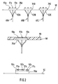
- Three strands of electrical cables 10A, 10B, 10C are unwound from corresponding supply drums 15A, 15B and 15C and fed to an injection mold 20 over a predetermined length, for example 50 mm in length.
- the casting mold 20 has, for example, an inner length of approximately 1 cm.
- the individual cables 10A, 10B, 10C are guided at a predetermined distance from one another. This can be accomplished, for example, by means of a perforated disk 25 before entering the injection mold 20.
- the injection mold 20 is designed with respect to its longitudinal dimension so that a substantial part of the length of the electrical cables 10A, 10B and 10C remains in front of the injection mold after the feeding process and is therefore not included in the injection molding process.
- Plastic extrusion is then introduced into the injection mold via an opening 30 through an extruder (not shown). After the mass has hardened, the injection mold is opened and the strand with the cables 10A, 10B and 10C is again transported further by the predetermined length. In this way, a continuous cable harness is created with connector housing blocks 35A, 35B, 35C arranged thereon and produced by the repetitive injection molding process.
- the semi-finished product used on the drums 15A, 15B and 15C preferably preferably has a copper wire, in particular also made of 135-Cu compound (for example, to be obtained from Hudson International).
- the wire preferably has a diameter of 0.1 mm.
- This insulating jacket is preferably made of laminated unbreakable modified polytetrafluoroethylene ("HSM” - High Strength Modified PTFE).
- HSM laminated unbreakable modified polytetrafluoroethylene
- This HSM material consists of expanded polytetrafluoroethylene (ePTFE), which is laminated with ethylene tetrafluoroethylene (“Tefzel”).
- ePTFE expanded polytetrafluoroethylene
- Tefzel ethylene tetrafluoroethylene
- Typical embodiments use ePTFE of a compressed thickness of 0.5 to 0.7 mil with a tensile strength greater than about 6 x 10 4 psi.
- An embodiment is also possible in which the insulating jacket is made entirely or partially of polyester.
- the plastic used for injection molding the connector housing block can be any type of hard plastic.
- a galvanizable form of acrilonitrylbutadiene styrene (ABS or ABS / PHAT) is preferably used.
- the continuous cable harness can be blown with hot air 40 in areas between two successive connector housing blocks 35A, 35B, 35C in order to glue the insulating sleeves together, taking advantage of the fact that the Tefzel layer has a melting point of around 250 ° C has and can be softened by heat application.
- the hot air temperature is chosen so that the material of the insulating jacket becomes sufficiently plastic for gluing.
- Tefzel has the advantage that, due to the low melting point, little thermal energy is transferred to the connector housing block 35A, 35B, 35C and to the inner jacket material. This protects the connector housing block 35A, 35B, 35C and the insulating jacket from heat damage.
- This process can also be carried out with other materials; however, it is preferable to ensure that the melting point of the thermoplastic material on the insulating jacket of the cables 15A, 15B, 15C used is lower than the melting point or the decomposition temperature of the material used for injection molding the connector housing blocks 35A, 35B, 35C and the material , from which the inner layer of the insulating jacket is made.
- the invention is not limited to the use of three cables. In principle, it can also be implemented with any other number of electrical wiring harnesses.
- the individual assembled cables are obtained as blanks by cutting one of the outer surfaces of the connector housing blocks 35A, 35B, 35C.
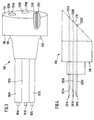
- FIG. 2 The further manufacturing steps are illustrated in FIG. 2 .
- the blanks 45A, 45B, 45C are inserted into a carrier module 50.
- the use of the carrier module 50 has the advantage that a large number of prefabricated cables can be manufactured at the same time, which considerably reduces the processing costs.
- the carrier module 50 essentially consists of a pane provided with openings 52A, 52B, 52C, the bonded cable harness sections 10A, 10B, 10C are passed down through these openings, whereas the corresponding connector housing blocks 35A, 35B, 35C are held by the opening edge. It proves to be advantageous if the edge of the openings 52A, 52B, 52C is provided with a recess (not shown) so that the upper sides of the connector housings 35A, 35B, 35C are flush with the upper side of the washer.
- the insulating sheaths of the cables 10A, 10B, 10C are removed from the surface of the connector housing block 35A, 35B, 35C by a length of approximately 2 to 3 mm. This process can be accomplished particularly advantageously by burning away the cladding material using laser light, for example from a CO 2 laser.
- the surfaces of the connector housing blocks 35A, 35B, 35C are covered with photoresist 55.
- the paint 55 must be selected so that it does not attack the plastic of the connector housing block 35A, 35B, 35C.
- the entire carrier module 50 with the blanks 40A, 40B, 40C is then immersed in liquid nitrogen for the temporary hardening of the lacquer layer and the plastic of the connector housing blocks 35A, 35B, 35C.
- the surfaces of the lacquer layer on the connector housing blocks 35A, 35B and 35C are then mechanically polished with the contactable wire stubs 51A, 51B, 51C protruding from them to form contact areas.
- a gold layer 52A, 52B, 52C is applied to the contactable core stubs 51A, 51B, 51C.
- the thickness of the gold layer 52A, 52B, 52C must be chosen so that it bridges the insulation layer of the wires in order to establish reliable contact between the wire and the outside world.
- the metal layer can be applied, for example, using known plasma application methods.
- the photoresist 55 is selected only because of its mechanical properties in the cryogenic state.
- the mechanical finishing of the contact areas of the wires 51A, 51B, 51C emerging from an outer surface of the connector housing blocks 35A, 35B, 35C can also be done in another way.
- another suitable masking agent can be used, e.g. Wax.
- the cover with a cover layer can be dispensed with.
- the covering with photoresist can be dispensed with if the application of a metal layer to the contactable core stumps 51A, 51B, 51C is dispensed with or if there is no risk of the formation of short-circuit bridges.
- FIG. 3 shows an assembled electrical cable according to the invention with electrical cores 101A, 101B, 101C and corresponding insulating sheaths 102A, 102B, 102C which are bonded together.
- the connector housing block 110 has an end face 115, which is provided with a contact area 120A, 120B, 120C for each wire 101A, 101B or 101C.
- the contact areas 120A, 120B and 120C are provided with a gold coating 125A, 125B, 125C.
- the prefabricated cable shown in FIG. 3 is used in such a way that two of these prefabricated cables are brought together in such a way that the respective end faces of the connector housing blocks provided with contact areas are mechanically placed against one another in such a way that electrical contact is produced between corresponding contact areas (not shown).
- embodiments with up to three wires prove to be particularly advantageous since up to three contact areas are always on the same level.
- sufficiently narrow tolerances are required in the face-side contact areas in order to ensure a uniform contact.
- FIG. 4 shows a schematic cross-sectional view of a second embodiment 200 of an assembled cable according to the invention with wires 201A, 201B, 201C, which are surrounded by insulating sheaths 202A, 202B, 202C analogously to FIG. 3 .
- the connector housing block 210 has a tapered end face 215 on which the contact areas 220A, 220B, 220C are arranged as shown in FIG. 5 .
- a self-cleaning effect is achieved by this beveled arrangement of the contact areas.
- the effective contact area is increased by an oblique cut, which, with appropriate dimensioning of the wire cross sections, can make it possible to dispense with gold plating which improves contact.
- FIG. 6A shows a schematic cross section through a connector bracket 300 with an inserted connector housing block 310.
- the connector clip 300 is designed as a cylindrical connector cap which has a body part 320 which has a cross section corresponding to the cross section of the connector housing block 310, the connector housing block 310 being received by the connector clip 300.
- the connector cap has a cable outlet part 330, which closes off the body part 320 on one side and through which this extends the cable 360 leading the connector housing block 310 is led out of the connector bracket 300 to the outside.
- the cable outlet part is preferably designed in such a way that at the end of the cable outlet, the bottom has an inward-facing, flexible indentation 332.
- the fuselage part 320 is adjoined on the other side by a coupling part 340 which is shaped such that a second connector housing block 310 ', as shown in FIG. 6B , can be accommodated therein, so that the contact areas of the two connector housing blocks touch accordingly.
- the indentation 332 presses elastically on the first connector housing block 310.
- the coupling part 340 has a latching device 390 in order to prevent the second connector housing block 310 'from falling out. Both connector housing blocks 310, 310 'are then mechanically prestressed between the locking device 390 and the indentation 332, so that the contact areas on both sides are under sufficient contact pressure for good contacting.
- the locking device 390 can be designed as an inwardly facing bead lip arranged at the outer end of the coupling part 340.
- the connector housing is expediently designed in terms of its spatial shape in such a way that the latching device 390 can grip securely. In the embodiment shown in FIG. 3 , a locking collar 130 is provided for this.
- the connector clip 300 can be made of plastic, for example LCP. When used with shielding or coaxial cables, it can be advantageous to manufacture them from metal or a conductive plastic.
- connector housing block and connector clip with a reverse polarity protection device (not shown). This can be done, for example, by providing a guide groove in the connector bracket happen in which a corresponding, integrally formed on the connector housing block engages.
- FIG. 7 shows a schematic perspective view of a third embodiment of a prefabricated cable 400 according to the invention.
- the contact regions 410A to 410E are arranged laterally projecting on an edge 420 between an end face 430 and a lateral surface 440 of the connector housing block 450.
- the wires of the cables 460A to 460E are respectively electrically connected to the contact areas 410A to 410E.
- a connector clip which is provided with internally arranged, longitudinally extending transition conductors which are adapted in terms of their spacing to the contact surface arrangement (not shown). These transition conductors facilitate perfect electrical contact between two paired contact areas of the first and second connector housing block (310, 310 ').
- FIG. 8 shows a schematic cross section through the cable material of a preferred embodiment of the assembled cable according to the invention.
- a core 510 made of a conductor, preferably a Cu material, is surrounded by an insulating jacket 520 made of particularly tear-resistant, non-thermoplastic material.
- the insulating jacket 520 is provided with an outer layer 530 made of thermoplastic material.
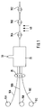
- FIG. 9A shows a schematic sectional view of a hearing device 600 according to the invention.
- the hearing device 600 has a hearing device housing 610, in which a conventional hearing device electronics 620 is installed.
- a prefabricated cable 630 according to the invention is connected to the hearing aid electronics 620.
- the cable 630 is guided through a small hole 640 from the inside of the hearing aid housing 610 to the outside.
- the prefabricated cable can in particular be used to temporarily connect the hearing device electronics 620 to an operating device (not shown).
- FIG. 9B shows a schematic sectional view of a human auditory canal 700 with a hearing aid 710 inserted therein.
- the assembled cable 720 is dimensioned such that the connector housing block 740 remains at the exit or outside the auditory canal 700 in the region of the ear cup 730.
Landscapes
- Engineering & Computer Science (AREA)
- Manufacturing & Machinery (AREA)
- Manufacturing Of Electrical Connectors (AREA)
- Connector Housings Or Holding Contact Members (AREA)
Applications Claiming Priority (2)
| Application Number | Priority Date | Filing Date | Title |
|---|---|---|---|
| DE19537724A DE19537724A1 (de) | 1995-10-10 | 1995-10-10 | Konfektioniertes Kabel, Herstellungsverfahren dafür sowie mit konfektioniertem Kabel versehenes Hörgerät |
| DE19537724 | 1995-10-10 |
Publications (2)
| Publication Number | Publication Date |
|---|---|
| EP0768739A2 true EP0768739A2 (fr) | 1997-04-16 |
| EP0768739A3 EP0768739A3 (fr) | 2000-03-29 |
Family
ID=7774493
Family Applications (1)
| Application Number | Title | Priority Date | Filing Date |
|---|---|---|---|
| EP96116195A Withdrawn EP0768739A3 (fr) | 1995-10-10 | 1996-10-09 | Cable façonné, procédé de fabrication, de celui-ci avec un cable façonné pour une prothèse auditive |
Country Status (3)
| Country | Link |
|---|---|
| EP (1) | EP0768739A3 (fr) |
| AU (1) | AU6800496A (fr) |
| DE (1) | DE19537724A1 (fr) |
Cited By (2)
| Publication number | Priority date | Publication date | Assignee | Title |
|---|---|---|---|---|
| WO2009049619A1 (fr) * | 2007-10-16 | 2009-04-23 | Estron A/S | Connecteur électrique pour dispositif auditif |
| US8608512B2 (en) | 2011-04-18 | 2013-12-17 | Fci Americas Technology, Llc | Cable connector |
Citations (6)
| Publication number | Priority date | Publication date | Assignee | Title |
|---|---|---|---|---|
| US2355913A (en) * | 1939-05-31 | 1944-08-15 | Simon Johanna Elly | Connecting device |
| FR1185592A (fr) * | 1956-11-05 | 1959-08-03 | Plessey Co Ltd | Connecteur à contact par aboutement |
| EP0539148A2 (fr) * | 1991-10-22 | 1993-04-28 | Pi (Medical) Corporation | Assemblage de câbles miniature biologiquement implantable |
| DE4209097A1 (de) * | 1992-03-20 | 1993-09-23 | Manfred Dipl Ing Mueller | Universelles steckverbindersystem |
| US5274917A (en) * | 1992-06-08 | 1994-01-04 | The Whitaker Corporation | Method of making connector with monolithic multi-contact array |
| WO1994001175A1 (fr) * | 1992-07-14 | 1994-01-20 | Schwarz Pharma Ag | Dispositif et procede pour la realisation d'un microconnecteur et ligne d'alimentation electrique comportant au moins un microconnecteur |
Family Cites Families (2)
| Publication number | Priority date | Publication date | Assignee | Title |
|---|---|---|---|---|
| DE4136663C2 (de) * | 1990-12-24 | 1994-04-07 | Kabelmetal Electro Gmbh | Vorrichtung zum Anbringen eines Teils eines elektrischen Steckverbinders an einer Leitung |
| ES2044811T1 (es) * | 1992-04-16 | 1994-01-16 | Leonische Drahtwerke Ag | Procedimiento para la fabricacion de un conjunto de cables. |
-
1995
- 1995-10-10 DE DE19537724A patent/DE19537724A1/de not_active Withdrawn
-
1996
- 1996-10-07 AU AU68004/96A patent/AU6800496A/en not_active Abandoned
- 1996-10-09 EP EP96116195A patent/EP0768739A3/fr not_active Withdrawn
Patent Citations (6)
| Publication number | Priority date | Publication date | Assignee | Title |
|---|---|---|---|---|
| US2355913A (en) * | 1939-05-31 | 1944-08-15 | Simon Johanna Elly | Connecting device |
| FR1185592A (fr) * | 1956-11-05 | 1959-08-03 | Plessey Co Ltd | Connecteur à contact par aboutement |
| EP0539148A2 (fr) * | 1991-10-22 | 1993-04-28 | Pi (Medical) Corporation | Assemblage de câbles miniature biologiquement implantable |
| DE4209097A1 (de) * | 1992-03-20 | 1993-09-23 | Manfred Dipl Ing Mueller | Universelles steckverbindersystem |
| US5274917A (en) * | 1992-06-08 | 1994-01-04 | The Whitaker Corporation | Method of making connector with monolithic multi-contact array |
| WO1994001175A1 (fr) * | 1992-07-14 | 1994-01-20 | Schwarz Pharma Ag | Dispositif et procede pour la realisation d'un microconnecteur et ligne d'alimentation electrique comportant au moins un microconnecteur |
Cited By (2)
| Publication number | Priority date | Publication date | Assignee | Title |
|---|---|---|---|---|
| WO2009049619A1 (fr) * | 2007-10-16 | 2009-04-23 | Estron A/S | Connecteur électrique pour dispositif auditif |
| US8608512B2 (en) | 2011-04-18 | 2013-12-17 | Fci Americas Technology, Llc | Cable connector |
Also Published As
| Publication number | Publication date |
|---|---|
| DE19537724A1 (de) | 1997-04-17 |
| AU6800496A (en) | 1997-04-17 |
| EP0768739A3 (fr) | 2000-03-29 |
Similar Documents
| Publication | Publication Date | Title |
|---|---|---|
| DE19948819C2 (de) | Heizleiter mit einem Anschlußelement und/oder einem Abschlußelement sowie ein Verfahren zur Herstellung desselben | |
| DE10218398B4 (de) | Verfahren zur Herstellung einer Abzweigverbindung an einem abgeschirmten Leiter | |
| DE19800099C2 (de) | Verfahren zur Herstellung eines Leitungsverbinders | |
| EP1689057B1 (fr) | Dispositif antiflambage pour un câble électrique | |
| DE69002994T2 (de) | Bearbeitung von Kabelenden beim Herstellen von elektrischen Kabelbäumen. | |
| DE4340425A1 (de) | Hochimpedanz-Leitungskabel mit abstreifbarer Isolierung | |
| EP0960038B1 (fr) | Mode de fabrication d'un harnais de cables | |
| DE10218400A1 (de) | Abschirmanordnung an einem Abschirmflachkabel und Verfahren zu deren Herstellung | |
| DE19822716C2 (de) | Verfahren zum Wasserdichtmachen des Einführbereichs eines ummantelten Leiters | |
| DE19934967C2 (de) | Wasserdichter Verbinder | |
| EP0542005A1 (fr) | Procédé de fabrication de connexion électrique entre deux conduites électriques | |
| DE2607058A1 (de) | Verfahren und form zum herstellen von geformten kabel-spleisstellen | |
| EP0914271B1 (fr) | Procede de fabrication d'un module prefabrique de porte de vehicule | |
| DE10218399B4 (de) | Anordnung mit einem mehradrigen Abschirmkabel | |
| DE19909335A1 (de) | Verbindungsstruktur für ummantelte Leitungen | |
| DE102016114945A1 (de) | Elektrische Flachleiteranordnung und Herstellungsverfahren für eine solche | |
| DE3636927C2 (fr) | ||
| DE3002320A1 (de) | Geraete-anschlusstecker und verfahren zu dessen herstellung | |
| DE69423054T3 (de) | Glasscheibe mit Anschlusselement | |
| EP3497704A1 (fr) | Ensemble conducteur électrique plat et procédé de production correspondant | |
| DE10255070B4 (de) | Anordnung zum Verbinden eines Erdungskabels mit einem flachen abgeschirmten Kabel und Verfahren zum Verbinden derselben | |
| EP0768739A2 (fr) | Cable façonné, procédé de fabrication, de celui-ci avec un cable façonné pour une prothèse auditive | |
| DE69401118T2 (de) | Elektrischer Kabel für Verbinder sowie Produktionsverfahren und Einrichtung | |
| DE3725124A1 (de) | Verfahren zum wasser- bzw. wasserdampfdichten umkleiden von leiterverbindungen | |
| EP1176613B1 (fr) | Câble comprenant au moins un élément de transmission |
Legal Events
| Date | Code | Title | Description |
|---|---|---|---|
| PUAI | Public reference made under article 153(3) epc to a published international application that has entered the european phase |
Free format text: ORIGINAL CODE: 0009012 |
|
| AK | Designated contracting states |
Kind code of ref document: A2 Designated state(s): BE ES FR GB IT NL SE |
|
| PUAL | Search report despatched |
Free format text: ORIGINAL CODE: 0009013 |
|
| AK | Designated contracting states |
Kind code of ref document: A3 Designated state(s): BE ES FR GB IT NL SE |
|
| STAA | Information on the status of an ep patent application or granted ep patent |
Free format text: STATUS: THE APPLICATION IS DEEMED TO BE WITHDRAWN |
|
| 18D | Application deemed to be withdrawn |
Effective date: 20000930 |