EP0768467A1 - Lagereinheit - Google Patents
Lagereinheit Download PDFInfo
- Publication number
- EP0768467A1 EP0768467A1 EP96116344A EP96116344A EP0768467A1 EP 0768467 A1 EP0768467 A1 EP 0768467A1 EP 96116344 A EP96116344 A EP 96116344A EP 96116344 A EP96116344 A EP 96116344A EP 0768467 A1 EP0768467 A1 EP 0768467A1
- Authority
- EP
- European Patent Office
- Prior art keywords
- opposing faces
- bearing unit
- pair
- movable member
- bearing
- Prior art date
- Legal status (The legal status is an assumption and is not a legal conclusion. Google has not performed a legal analysis and makes no representation as to the accuracy of the status listed.)
- Granted
Links
Images


Classifications
-
- F—MECHANICAL ENGINEERING; LIGHTING; HEATING; WEAPONS; BLASTING
- F16—ENGINEERING ELEMENTS AND UNITS; GENERAL MEASURES FOR PRODUCING AND MAINTAINING EFFECTIVE FUNCTIONING OF MACHINES OR INSTALLATIONS; THERMAL INSULATION IN GENERAL
- F16C—SHAFTS; FLEXIBLE SHAFTS; ELEMENTS OR CRANKSHAFT MECHANISMS; ROTARY BODIES OTHER THAN GEARING ELEMENTS; BEARINGS
- F16C35/00—Rigid support of bearing units; Housings, e.g. caps, covers
-
- F—MECHANICAL ENGINEERING; LIGHTING; HEATING; WEAPONS; BLASTING
- F16—ENGINEERING ELEMENTS AND UNITS; GENERAL MEASURES FOR PRODUCING AND MAINTAINING EFFECTIVE FUNCTIONING OF MACHINES OR INSTALLATIONS; THERMAL INSULATION IN GENERAL
- F16C—SHAFTS; FLEXIBLE SHAFTS; ELEMENTS OR CRANKSHAFT MECHANISMS; ROTARY BODIES OTHER THAN GEARING ELEMENTS; BEARINGS
- F16C27/00—Elastic or yielding bearings or bearing supports, for exclusively rotary movement
-
- F—MECHANICAL ENGINEERING; LIGHTING; HEATING; WEAPONS; BLASTING
- F04—POSITIVE - DISPLACEMENT MACHINES FOR LIQUIDS; PUMPS FOR LIQUIDS OR ELASTIC FLUIDS
- F04D—NON-POSITIVE-DISPLACEMENT PUMPS
- F04D19/00—Axial-flow pumps
- F04D19/02—Multi-stage pumps
- F04D19/04—Multi-stage pumps specially adapted to the production of a high vacuum, e.g. molecular pumps
- F04D19/048—Multi-stage pumps specially adapted to the production of a high vacuum, e.g. molecular pumps comprising magnetic bearings
-
- F—MECHANICAL ENGINEERING; LIGHTING; HEATING; WEAPONS; BLASTING
- F04—POSITIVE - DISPLACEMENT MACHINES FOR LIQUIDS; PUMPS FOR LIQUIDS OR ELASTIC FLUIDS
- F04D—NON-POSITIVE-DISPLACEMENT PUMPS
- F04D29/00—Details, component parts, or accessories
- F04D29/66—Combating cavitation, whirls, noise, vibration or the like; Balancing
- F04D29/661—Combating cavitation, whirls, noise, vibration or the like; Balancing especially adapted for elastic fluid pumps
- F04D29/668—Combating cavitation, whirls, noise, vibration or the like; Balancing especially adapted for elastic fluid pumps damping or preventing mechanical vibrations
-
- F—MECHANICAL ENGINEERING; LIGHTING; HEATING; WEAPONS; BLASTING
- F16—ENGINEERING ELEMENTS AND UNITS; GENERAL MEASURES FOR PRODUCING AND MAINTAINING EFFECTIVE FUNCTIONING OF MACHINES OR INSTALLATIONS; THERMAL INSULATION IN GENERAL
- F16C—SHAFTS; FLEXIBLE SHAFTS; ELEMENTS OR CRANKSHAFT MECHANISMS; ROTARY BODIES OTHER THAN GEARING ELEMENTS; BEARINGS
- F16C32/00—Bearings not otherwise provided for
- F16C32/04—Bearings not otherwise provided for using magnetic or electric supporting means
- F16C32/0406—Magnetic bearings
- F16C32/0408—Passive magnetic bearings
- F16C32/0423—Passive magnetic bearings with permanent magnets on both parts repelling each other
- F16C32/0425—Passive magnetic bearings with permanent magnets on both parts repelling each other for radial load mainly
-
- F—MECHANICAL ENGINEERING; LIGHTING; HEATING; WEAPONS; BLASTING
- F16—ENGINEERING ELEMENTS AND UNITS; GENERAL MEASURES FOR PRODUCING AND MAINTAINING EFFECTIVE FUNCTIONING OF MACHINES OR INSTALLATIONS; THERMAL INSULATION IN GENERAL
- F16C—SHAFTS; FLEXIBLE SHAFTS; ELEMENTS OR CRANKSHAFT MECHANISMS; ROTARY BODIES OTHER THAN GEARING ELEMENTS; BEARINGS
- F16C32/00—Bearings not otherwise provided for
- F16C32/04—Bearings not otherwise provided for using magnetic or electric supporting means
- F16C32/0406—Magnetic bearings
- F16C32/044—Active magnetic bearings
- F16C32/0474—Active magnetic bearings for rotary movement
- F16C32/0476—Active magnetic bearings for rotary movement with active support of one degree of freedom, e.g. axial magnetic bearings
- F16C32/0478—Active magnetic bearings for rotary movement with active support of one degree of freedom, e.g. axial magnetic bearings with permanent magnets to support radial load
-
- F—MECHANICAL ENGINEERING; LIGHTING; HEATING; WEAPONS; BLASTING
- F16—ENGINEERING ELEMENTS AND UNITS; GENERAL MEASURES FOR PRODUCING AND MAINTAINING EFFECTIVE FUNCTIONING OF MACHINES OR INSTALLATIONS; THERMAL INSULATION IN GENERAL
- F16C—SHAFTS; FLEXIBLE SHAFTS; ELEMENTS OR CRANKSHAFT MECHANISMS; ROTARY BODIES OTHER THAN GEARING ELEMENTS; BEARINGS
- F16C39/00—Relieving load on bearings
- F16C39/06—Relieving load on bearings using magnetic means
- F16C39/063—Permanent magnets
-
- F—MECHANICAL ENGINEERING; LIGHTING; HEATING; WEAPONS; BLASTING
- F16—ENGINEERING ELEMENTS AND UNITS; GENERAL MEASURES FOR PRODUCING AND MAINTAINING EFFECTIVE FUNCTIONING OF MACHINES OR INSTALLATIONS; THERMAL INSULATION IN GENERAL
- F16C—SHAFTS; FLEXIBLE SHAFTS; ELEMENTS OR CRANKSHAFT MECHANISMS; ROTARY BODIES OTHER THAN GEARING ELEMENTS; BEARINGS
- F16C2360/00—Engines or pumps
- F16C2360/44—Centrifugal pumps
- F16C2360/45—Turbo-molecular pumps
Definitions
- the present invention relates in general to a magnetic bearing, and relates in particular to a magnetic bearing unit suitable for applications in sealed vacuum systems such as turbo-molecular pumps.
- a type of magnetic bearing in which a "passive" magnetic bearing having permanent magnets within to generate a radial force to support the rotation axis in a radial direction and an "active" magnetic bearing to generate an axial resistance force to resist an axial force for actively controlling the rotation axis in the axial direction, is often referred to as a uniaxial control-type magnetic bearing.
- the passive bearing utilizes the radial repulsive force generated between two permanent magnets provided in the rotor and in the stator, but there is no acting force between them in the axial direction.
- a relative displacement is generated between the rotor and the stator because of, for example, the precision limitation in fabricating the component parts, an axial magnetic force is generated between the permanent magnets which affects the magnetic field of the permanent magnets, causing an instability in controlling the operation of the bearing unit. Therefore, in order to have the rotor levitated securely, it is most preferable to keep the rigidity of the member which supports the stator-side of the permanent magnets in the axial direction as high as possible.
- the magnetic force offered by the permanent magnets themselves does not provide any damping factor, and once the rotor begins to swing wildly at a certain rotational speed (at the resonance point) and should the rotor touch the protective bearing at this stage, screeching noise is generated and the rotational speed can no longer be increased.
- the rotor-bearing mechanism be provided with a damping mechanism for generating different capabilities for position-retention in the radial and in the axial directions.
- a damping mechanism for generating different capabilities for position-retention in the radial and in the axial directions.
- An example of such a mechanism is disclosed in a Japanese Laid-Open Patent Application, H2-125106, which comprises an intermediate component member disposed between a rotor and a stator, and a damping member disposed between the intermediate component member and the rotor for producing a damping effect.
- This system utilizes the magnetic coupling generated between the stator and the intermediate component member for centering of the intermediate component member within the stator.
- a magnetic bearing unit comprising: a fixed member; a rotating member relatively rotating to the fixed member, the rotating member being supported in a radial direction by magnetic effects generated by permanent magnets arranged within a passive radial magnetic bearing member and supported in an axial direction by an actively-controlled axial magnetic bearing member; a movable member arranged between the fixed member and the rotating member, the passive magnetic member being arranged between the movable member and the rotating member, at least first and second pairs of axially opposing faces being provided, each opposing face being respectively on the fixed member and the movable member; and a biasing means in functional association with the movable member for forcing the movable member to shorten a spacing between the first pair of opposing faces; wherein the first pair of opposing faces is formed with a recess having a curved cross sectional shape on each of the opposing faces, a plurality of balls having a radius not more than a radius of the recess are disposed in the recess, and the second pair of oppos
- the first pair of opposing faces and the balls are made to contact intimately by the action of the biasing device so as to produce a cantilever type suspension effects to hold in place within the fixed member.
- the opposite end of the movable member is free to move somewhat in the radial direction, thereby providing energy absorption brought about by the action of the damping member.
- An aspect of the bearing unit is that the permanent magnets in the passive radial bearing member and in the movable members are arranged in an offset position in an axial direction with respect to each other so that they may act as a biasing device. By simply changing the axial position of the passive radial bearing member, a strong biasing means can be formed.
- the rotating member is provided with at least two of the movable member disposed separately along the axial direction, thus increasing the stability of the bearing unit.
- a third pair of axially opposing faces is disposed respectively on the movable member and the rotating member in an opposite orientation to the first pair of opposing faces; and the third pair of opposing faces is provided with a recess having a curved cross sectional shape in a radial cross section, and a plurality of balls are disposed within the recess. Because the first and the third pairs of opposing faces are in opposite orientation to each other, the movable members are fixed in place with respect to the fixed member by two sets of balls so that one set in the first pair of opposing faces are in compression and the other set of balls in the third pair have some slack. The slack distance can be absorbed with a small quantity of deviation in the radial direction by selecting diameter difference of the recess and balls or spacing distance between those opposing faces.
- damping members are placed in compression in the second pair of opposing faces to act as a biasing device, thus utilizing all the components at their high efficiency.
- the recess is formed so as to extend in the circumferential direction, thereby providing a uniform action in all directions.
- the damping device is cylindrical in shape so that the damping effects can be generated isometrically.
- the damping device is attached to the recess by fitting in each groove formed in the second pair of opposing faces so that it can produce strong mechanical coupling.
- Another aspect of the bearing unit is that emergency protection bearing members are provided in such a way that the movable member and the protection bearings are integral so as to facilitate centering and assure precision in reassemble.
- the final aspect of the bearing unit is that a sum of a spacing distance in a radial direction between the rotating member and the emergency protection bearing member and a spacing distance between the movable member and the fixed member is not more than a spacing distance in a radial direction between the rotating member and the fixed member so that even when the rotating member vibrates severely, there will be no contact between the rotor and the stator.
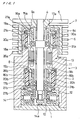
- Figure 1 is a cross sectional view of a bearing unit of the present invention applied to a turbo-molecular pump.
- Figure 2 is an enlarged view of the upper section of the apparatus shown in Figure 1.
- Figure 3 is a further enlarged detail view of the upper section shown in Figure 2.
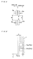
- Figure 4 is an enlarged view of the compression and biasing sections in Figure 2.
- Figure 5 is an illustration of an arrangement for the top and bottom movable components.
- Figure 6 is an illustration to show the emergency protection bearing member in relation to the rotor and the stator.
- Figure 1 shows an embodiment of the bearing unit of the present invention applied to a turbo-molecular pump, and the unit comprises: a stator (fixed member) 3 having a bottom 1 and a cylindrical side wall 2; and a rotor (rotating member) 7 having a main shaft 4, a circular plate section 5 and a cylindrical section 6 including a plurality of impellers 6c.
- the main shaft 4 is oriented vertically, however, this is only for the purpose of illustration and explaining the positional relation for the top and bottom sections of the apparatus, and does not mean that the unit can be operated only in this orientation.
- the component parts in the top section of the bearing unit are given a suffix "a or A" and the components parts in the bottom section are given a suffix "b or B" to indicate their respective place in the unit.
- the main shaft 4 is provided with a motor-rotor 8 in the center section, and a pair of top permanent magnets 9a and the bottom permanent magnets 9b to radially support the rotor 7, which are referred as the rotor-side permanent magnets 9a, 9b.
- the bottom end of the main shaft 4 incorporates an assembled axial disc 10 for attachment to the main shaft 4.
- the stator-side of the bearing unit is provided with a motor-stator 11 to positionally correspond with the motor-rotor 8, and an electromagnet 12 is provided on the bottom region to surround the axial disc 10.
- the bearing unit is provided between the rotor 7 and the stator 3 with a motor section 13 in the middle section of the unit for the purpose of rotational drive thereof, and an axial magnetic bearing 14 in the bottom region of the unit for the purpose of axial support thereof.
- the axial magnetic bearing 14 is provided with an axial displacement sensor 14a to detect the axial position of the rotor 7 and the output signal from the sensor 14a is forwarded to a controller for feedback control of the axial magnetic bearing 14.
- the levitating force for the rotor 7 in the axial direction is controlled to maintain the axial position of the rotor 7 by regulating the attraction force of the upper and lower electromagnets 12 according to the output signal.
- the axial magnetic bearing 14 conducts an active control of the levitated position of the rotor by regulating the position of the rotor 7 in accordance with the signals generated by the position sensor.
- an upper movable member 15a and a lower movable member 15b are disposed between the rotor 7 and the stator 3, there are disposed an upper movable member 15a and a lower movable member 15b.
- These members are cylindrical in shape and are made of a material such as high toughness metals, and a plurality of ring-shaped permanent magnets 16a, 16b are attached to the interior surface thereof, and these permanent magnets in combination with the permanent magnets 9a, 9b on the main shaft 4 constitute a passive radial bearings 17a, 17b seen in the cross sectional drawing shown in Figures 1 and 2.
- the permanent magnets on the rotor-side and the stator-side are installed so that the like poles face each other (for example, an N-pole of the rotor 7 faces an N-pole of the stator 3), thereby maintaining the rotor 7 in the central position by the repulsive forces between the like poles.
- each of the movable members 15a, 15b there are outer discs 18a, 18b, 19a, 19b which protrude radially outward in the upper and lower sections of the movable members.
- Recesss 20a, 20b are formed, respectively, on the interior surface of the cylindrical wall 2 of the stator 3 to positionally correspond with these outer discs 18a ⁇ 19b.
- circumferential grooves (recesses) 22A, 22B, 23A, 23B, 24A, 24B, 25A, 25B having arcuate sectional shape are formed, respectively: on the bottom surfaces 22a, 22b on the recesses 20a, 20b; on the bottom surfaces 23a, 23b of the lower outer discs 18a, 18b; top surfaces 24a, 24b of the recesses 20a, 20b; and the upper surfaces 25a, 25b of the upper outer discs 19a, 19b.
- These circular grooves are provided with small balls 26a, 26b, 27a, 27b having a radius which is smaller than the radius R of the circular grooves, arranged in the peripheral direction of the grooves 22A ⁇ 25B.
- the surfaces 22a, 22b, 23a, 23b construct a first pair of opposing faces
- the surfaces 28a, 28b, 29a, 29b construct a third pair of opposing faces.
- These first and second pairs of opposing surfaces are in an opposite orientation to each other, that is, the first pair of opposing faces 22a, 22b, 23a, 23b is directed downward and the third pair of opposing faces 28a, 28b, 29a, 29b is directed upward when seen from the stator 3 to the movable member 15a.
- Attachment grooves 28A, 28B, 29A, 29B having a rectangular cross sectional shape are provided on the top surfaces 28a, 28b of the lower outer discs 18a, 18b and the bottom surfaces 29a, 29b of the inner discs 21a, 21b to extend in the peripheral direction.
- the surfaces 28a, 28b, 29a, 29b construct a second pair of opposing faces.
- the attachment grooves 28A, 28B, 29A, 29B are elastically fitted with cylinder-shaped damping members 30a, 30b made of an elastic material such as synthetic rubber.
- the dimension of the damping members 30a, 30b is chosen in a manner that they are installed to be in compression between the opposing faces 28a ⁇ 29b, so that the movable members 15a, 15b are biased downwards by the forces exerted by the damping members 30a, 30b.
- the dimensions of the spacings formed between the circumferential grooves 22A ⁇ 25B and the balls 26a ⁇ 27b are determined by the distances of the top and bottom surfaces of the recesss 20a, 20b, the distances of the top surfaces 25a, 25b of the upper outer discs 19a, 19b and the lower surfaces 23a, 23b of the lower outer discs 18a, 18b, the depth of the circumferential grooves 22A ⁇ 25B, and the radius of the balls 26a ⁇ 27b.
- the dimensions are chosen so as to produce spacings of very minute size.
- the spacing distance B between the rotor-side permanent magnets 9a, 9b is slightly different than the spacing distance A on the upper and lower stator-side permanent magnets 16a, 16b of the movable members 15a, 15b.
- the dimension of the spacing distance on the rotor-side is larger than that on the stator-side.
- each of the movable members 15a, 15b is provided, respectively, with a protection bearing member (emergency protection bearing member) 31a, 31b in order to prevent a direct contact between the rotor 7 and the stator 3 by restricting the degree of displacement of the rotor 7, when the rotor 7 is not levitated or when there is an excess amount of vibration generated in the rotor 7.
- the radial spacing C between the movable member 15a, 15b and the stator 3 the spacing D between the rotor 7 and the movable members 15a, 15b and the spacing E between the rotor 7 and the stator 3 are related by a relation such that E>C+D. This relation is chosen so that even if the rotor 7 is subjected to a large displacement, the rotor 7 does not contact the stator 3.
- damping members 30a, 30b are coupled to the movable members 15a, 15b and the stator 3 by a mechanical coupling attachment to the attachment grooves 28A ⁇ 29B so as to produce a high degree of precision in positioning.
- the cross sectional shape of the bearing unit is such that the circumferential grooves 22A, 23B accommodating the balls 26a, 26b on the first opposing faces 22a, 23b is an arc with a radius R which is minutely larger than the radius r of the balls. Centering of the movable members 15a, 15b with respect to the stator 3 is thus achieved by the mutual interaction between the balls and the grooves, as well as restricting the amount of radial movement so as to maintain the centered state.
- the damping members 30a, 30b are made of an elastic cylinder whose one end is fixed to the movable member 15a, 15b while the opposite end is fixed to the stator 3 so that the damping members 30a, 30b are supported by a cantilever suspension.
- the entire cylindrical damping members are made to deform thus consuming the deformation energy most effectively as a unit, thereby allowing to exhibit a maximum damping capacity.
- This arrangement also permits the retention rigidity of the movable members 15a, 15b to be retained small within a minute radial distance range, thereby effectively reducing the vibration of the rotor 7.
- the bearing unit having the design presented above can be operated in any desired orientation, in a horizontal or slanted orientation by using essentially the same operational procedure.
- the presence of the minute spacing between the third opposing faces 24a ⁇ 25b generates a minute shift of the main shaft in the radial direction; however, the degree of shift is governed by the dimension of the minute spacing given by the difference between the radii of the circumferential grooves 24A ⁇ 25B and the balls 27a, 27b.
- the dimensions of the spacings and the radius difference are chosen so that any radial shift which might occur would not interfere with the operational characteristics of the bearing unit.
- the protection bearing members 31a, 31b (emergency protection bearings) integrally with the movable member 15a, 15b, it facilitates centering of the stator-side of the unit, that is, centering between the permanent magnets 16a, 16b on the movable members 15a, 15b and the protection bearings 31a, 31b. Also, high precision in manufacturing the protection device is possible by suitably managing the shapes and the dimensions of the movable members 15a, 15b and the stator 3.
- the rotor in the radial direction is supported by a passive bearing component utilizing permanent magnets, and the stability in the axial direction is provided by an active bearing component having electromagnets and displacement sensors.
- the bearing unit of such a construction produces the following advantages.
- the invention relates to a bearing unit comprising:
Applications Claiming Priority (3)
| Application Number | Priority Date | Filing Date | Title |
|---|---|---|---|
| JP7289343A JP3046533B2 (ja) | 1995-10-11 | 1995-10-11 | 軸受ユニット |
| JP28934395 | 1995-10-11 | ||
| JP289343/95 | 1995-10-11 |
Publications (2)
| Publication Number | Publication Date |
|---|---|
| EP0768467A1 true EP0768467A1 (de) | 1997-04-16 |
| EP0768467B1 EP0768467B1 (de) | 2003-01-22 |
Family
ID=17741982
Family Applications (1)
| Application Number | Title | Priority Date | Filing Date |
|---|---|---|---|
| EP96116344A Expired - Lifetime EP0768467B1 (de) | 1995-10-11 | 1996-10-11 | Lagereinheit |
Country Status (5)
| Country | Link |
|---|---|
| US (1) | US5679992A (de) |
| EP (1) | EP0768467B1 (de) |
| JP (1) | JP3046533B2 (de) |
| KR (1) | KR100408112B1 (de) |
| DE (1) | DE69625870T2 (de) |
Cited By (10)
| Publication number | Priority date | Publication date | Assignee | Title |
|---|---|---|---|---|
| EP0867627A3 (de) * | 1997-03-26 | 2000-07-26 | Pfeiffer Vacuum GmbH | Dämpfungssystem für magnetisch gelagerte Rotoren |
| EP1118774A2 (de) * | 1999-12-21 | 2001-07-25 | Seiko Seiki Kabushiki Kaisha | Vakuumpumpe |
| FR2804476A1 (fr) * | 2000-01-31 | 2001-08-03 | Cit Alcatel | Systeme amortisseur et centreur de roulement pour pompe a vide sur palier magnetique |
| EP1270949A1 (de) * | 2001-06-22 | 2003-01-02 | BOC Edwards Technologies, Limited | Vakuumpumpe |
| EP1669608A3 (de) * | 2004-11-24 | 2007-01-24 | Pfeiffer Vacuum GmbH | Vakuumpumpe |
| EP2749780A1 (de) * | 2012-12-26 | 2014-07-02 | Skf Magnetic Mechatronics | Hybride magnetische Lagerung eines Rotors |
| CN107387560A (zh) * | 2017-08-29 | 2017-11-24 | 南京磁谷科技有限公司 | 一种不等厚推力磁轴承结构 |
| WO2018001811A1 (de) * | 2016-06-29 | 2018-01-04 | Leybold Gmbh | Vakuumpumpe |
| FR3112172A1 (fr) * | 2020-11-30 | 2022-01-07 | Pfeiffer Vacuum | Pompe à vide sèche |
| WO2023029538A1 (zh) * | 2021-08-30 | 2023-03-09 | 珠海格力电器股份有限公司 | 磁悬浮轴承、电机、压缩机和空调器 |
Families Citing this family (24)
| Publication number | Priority date | Publication date | Assignee | Title |
|---|---|---|---|---|
| US5944489A (en) * | 1996-12-11 | 1999-08-31 | Crane Co. | Rotary fluid pump |
| US5969452A (en) * | 1998-11-13 | 1999-10-19 | Sundstrand Corporation | Magnetic bearing construction |
| DE10022062A1 (de) * | 2000-05-06 | 2001-11-08 | Leybold Vakuum Gmbh | Maschine, vorzugsweise Vakuumpumpe, mit Magnetlagern |
| JP2002317340A (ja) * | 2001-02-01 | 2002-10-31 | Neumag Gmbh & Co Kg | 糸を案内し、加熱しかつ搬送するためのゴデット |
| JP4106218B2 (ja) * | 2001-02-01 | 2008-06-25 | ノイマーク ゲゼルシャフト ミット ベシュレンクテル ハフツング ウント コンパニー コマンディートゲゼルシャフト | 少なくとも1つの糸を案内するためのゴデット |
| US6524005B2 (en) | 2001-06-04 | 2003-02-25 | Honeywell International, Inc. | Touchdown bearing assembly with actuator ring assembly |
| US7679245B2 (en) * | 2001-09-17 | 2010-03-16 | Beacon Power Corporation | Repulsive lift systems, flywheel energy storage systems utilizing such systems and methods related thereto |
| GB0309830D0 (en) * | 2003-04-29 | 2003-06-04 | Boc Group Plc | A vacuum pump |
| DE102006037187A1 (de) * | 2006-08-09 | 2008-02-21 | Pfeiffer Vacuum Gmbh | Anordnung zur Lagerung einer Welle einer Vakuumpumpe |
| US8513826B2 (en) * | 2008-06-26 | 2013-08-20 | Ed Mazur | Wind turbine |
| DE102008033758B3 (de) * | 2008-07-18 | 2009-12-10 | Siemens Aktiengesellschaft | Lageranordnung und Lagerbock mit einem magnetischen Radiallager und einem Fanglager für eine rotierende Maschine |
| US8242649B2 (en) * | 2009-05-08 | 2012-08-14 | Fradella Richard B | Low-cost minimal-loss flywheel battery |
| EP2494187A4 (de) | 2009-10-29 | 2013-07-10 | Oceana Energy Co | Energieumwandlungssysteme und -verfahren |
| KR101283148B1 (ko) | 2011-05-04 | 2013-07-05 | 고려대학교 산학협력단 | 자기 베어링 모터 시스템 및 이를 이용한 유체 펌프 |
| US9048701B2 (en) * | 2011-08-30 | 2015-06-02 | Siemens Industry, Inc. | Passive magnetic bearings for rotating equipment including induction machines |
| CN102425556B (zh) * | 2011-11-11 | 2014-07-02 | 北京中科科仪股份有限公司 | 一种获取磁悬浮分子泵转子径向悬浮中心的方法 |
| DE102012216450A1 (de) * | 2012-09-14 | 2014-03-20 | Pfeiffer Vacuum Gmbh | Verfahren zum Zentrieren einer Vakuumpumpe oder einer Rotationseinheit für eine Vakuumpumpe |
| CN103236759B (zh) * | 2013-04-22 | 2016-07-06 | 南京工业大学 | 一种磁悬浮轴承盘式精密空调风机 |
| FR3018010B1 (fr) * | 2014-02-21 | 2016-03-11 | Skf Magnetic Mechatronics | Ensemble modulaire de moteur et paliers magnetiques et procede de fabrication |
| CN105650117B (zh) * | 2016-03-31 | 2017-12-19 | 珠海格力节能环保制冷技术研究中心有限公司 | 一种磁悬浮轴承组件和压缩机 |
| CN106321633B (zh) * | 2016-11-07 | 2018-06-05 | 湘潭大学 | 一种新型混合磁悬浮轴承 |
| US10465489B2 (en) * | 2016-12-28 | 2019-11-05 | Upwing Energy, LLC | Downhole blower system with passive radial bearings |
| EP3640481B1 (de) * | 2018-10-15 | 2023-05-03 | Pfeiffer Vacuum Gmbh | Vakuumpumpe |
| JP6960004B2 (ja) * | 2020-02-18 | 2021-11-05 | シナノケンシ株式会社 | 送風機 |
Citations (2)
| Publication number | Priority date | Publication date | Assignee | Title |
|---|---|---|---|---|
| EP0396849A1 (de) * | 1989-05-08 | 1990-11-14 | Nippon Ferrofluidics Corporation | Magnetische Lagervorrichtung |
| EP0470637A1 (de) * | 1990-08-10 | 1992-02-12 | Ebara Corporation | Turbomolekularpumpe |
-
1995
- 1995-10-11 JP JP7289343A patent/JP3046533B2/ja not_active Expired - Fee Related
-
1996
- 1996-10-09 US US08/729,031 patent/US5679992A/en not_active Expired - Lifetime
- 1996-10-10 KR KR1019960045078A patent/KR100408112B1/ko not_active IP Right Cessation
- 1996-10-11 EP EP96116344A patent/EP0768467B1/de not_active Expired - Lifetime
- 1996-10-11 DE DE69625870T patent/DE69625870T2/de not_active Expired - Fee Related
Patent Citations (2)
| Publication number | Priority date | Publication date | Assignee | Title |
|---|---|---|---|---|
| EP0396849A1 (de) * | 1989-05-08 | 1990-11-14 | Nippon Ferrofluidics Corporation | Magnetische Lagervorrichtung |
| EP0470637A1 (de) * | 1990-08-10 | 1992-02-12 | Ebara Corporation | Turbomolekularpumpe |
Cited By (16)
| Publication number | Priority date | Publication date | Assignee | Title |
|---|---|---|---|---|
| EP0867627A3 (de) * | 1997-03-26 | 2000-07-26 | Pfeiffer Vacuum GmbH | Dämpfungssystem für magnetisch gelagerte Rotoren |
| KR100732275B1 (ko) * | 1999-12-21 | 2007-06-25 | 비오씨 에드워즈 가부시키가이샤 | 진공펌프 |
| EP1118774A2 (de) * | 1999-12-21 | 2001-07-25 | Seiko Seiki Kabushiki Kaisha | Vakuumpumpe |
| EP1118774A3 (de) * | 1999-12-21 | 2002-10-30 | Seiko Instruments Inc. | Vakuumpumpe |
| US6575713B2 (en) | 1999-12-21 | 2003-06-10 | Seiko Instruments Inc. | Vaccum pump |
| FR2804476A1 (fr) * | 2000-01-31 | 2001-08-03 | Cit Alcatel | Systeme amortisseur et centreur de roulement pour pompe a vide sur palier magnetique |
| EP1122442A1 (de) * | 2000-01-31 | 2001-08-08 | Alcatel | Lagerzentrier-und Dämpfungssystem für eine Vakuumpumpe mit Magnetlagern |
| EP1270949A1 (de) * | 2001-06-22 | 2003-01-02 | BOC Edwards Technologies, Limited | Vakuumpumpe |
| US6840736B2 (en) | 2001-06-22 | 2005-01-11 | Boc Edwards Technologies Limited | Vacuum pump |
| EP1669608A3 (de) * | 2004-11-24 | 2007-01-24 | Pfeiffer Vacuum GmbH | Vakuumpumpe |
| EP2749780A1 (de) * | 2012-12-26 | 2014-07-02 | Skf Magnetic Mechatronics | Hybride magnetische Lagerung eines Rotors |
| WO2018001811A1 (de) * | 2016-06-29 | 2018-01-04 | Leybold Gmbh | Vakuumpumpe |
| CN107387560A (zh) * | 2017-08-29 | 2017-11-24 | 南京磁谷科技有限公司 | 一种不等厚推力磁轴承结构 |
| FR3112172A1 (fr) * | 2020-11-30 | 2022-01-07 | Pfeiffer Vacuum | Pompe à vide sèche |
| WO2022112229A1 (en) * | 2020-11-30 | 2022-06-02 | Pfeiffer Vacuum | Dry vacuum pump |
| WO2023029538A1 (zh) * | 2021-08-30 | 2023-03-09 | 珠海格力电器股份有限公司 | 磁悬浮轴承、电机、压缩机和空调器 |
Also Published As
| Publication number | Publication date |
|---|---|
| EP0768467B1 (de) | 2003-01-22 |
| KR970021811A (ko) | 1997-05-28 |
| JPH09105413A (ja) | 1997-04-22 |
| DE69625870T2 (de) | 2003-12-24 |
| US5679992A (en) | 1997-10-21 |
| JP3046533B2 (ja) | 2000-05-29 |
| KR100408112B1 (ko) | 2004-04-08 |
| DE69625870D1 (de) | 2003-02-27 |
Similar Documents
| Publication | Publication Date | Title |
|---|---|---|
| US5679992A (en) | Bearing unit | |
| US5561335A (en) | Integrated passive magnetic bearing system and spindle permanent magnet for use in a spindle motor | |
| US5894181A (en) | Passive magnetic bearing system | |
| US5453650A (en) | Face opposing type motor | |
| US20020074881A1 (en) | Passive magnetic support and damping system | |
| EP0470637A1 (de) | Turbomolekularpumpe | |
| US4502832A (en) | Turbo-molecular pump | |
| US5910695A (en) | Damping device for a magnetically supported rotor | |
| JP5303174B2 (ja) | 軸受装置 | |
| AU2024201252A1 (en) | Flywheel Systems And Flywheel Bearing Modules | |
| WO2019076419A1 (en) | FREE WHEEL SYSTEMS AND MODULES OF FREE WHEEL BEARINGS | |
| US20130207496A1 (en) | System and method for performing magnetic levitation in an energy storage flywheel | |
| JP2541371B2 (ja) | 高速度回転真空ポンプの磁気軸受構造 | |
| JP3406198B2 (ja) | スピンドルモータ及びスピンドルモータを採用した回転体装置 | |
| JPH03277807A (ja) | 気体軸受け構造 | |
| JP7429157B2 (ja) | 真空ポンプ | |
| JPH03272317A (ja) | 気体軸受け構造 | |
| JP2684882B2 (ja) | 回転体の振動抑制装置 | |
| KR100207987B1 (ko) | 자성물질을 이용한 반구 베어링 장치 | |
| JPH11190271A (ja) | エネルギ貯蔵装置 | |
| JPH04337114A (ja) | 減衰機構 | |
| JPH0614087Y2 (ja) | 磁気軸受装置 | |
| JPH0645698Y2 (ja) | 1軸制御型磁気軸受装置 | |
| JPS63235715A (ja) | 回転機械用振動減衰式軸受装置 | |
| JPH04339194A (ja) | 減衰機構 |
Legal Events
| Date | Code | Title | Description |
|---|---|---|---|
| PUAI | Public reference made under article 153(3) epc to a published international application that has entered the european phase |
Free format text: ORIGINAL CODE: 0009012 |
|
| AK | Designated contracting states |
Kind code of ref document: A1 Designated state(s): CH DE FR GB LI |
|
| 17P | Request for examination filed |
Effective date: 19971013 |
|
| 17Q | First examination report despatched |
Effective date: 20010601 |
|
| GRAG | Despatch of communication of intention to grant |
Free format text: ORIGINAL CODE: EPIDOS AGRA |
|
| GRAG | Despatch of communication of intention to grant |
Free format text: ORIGINAL CODE: EPIDOS AGRA |
|
| GRAH | Despatch of communication of intention to grant a patent |
Free format text: ORIGINAL CODE: EPIDOS IGRA |
|
| GRAH | Despatch of communication of intention to grant a patent |
Free format text: ORIGINAL CODE: EPIDOS IGRA |
|
| GRAA | (expected) grant |
Free format text: ORIGINAL CODE: 0009210 |
|
| AK | Designated contracting states |
Kind code of ref document: B1 Designated state(s): CH DE FR GB LI |
|
| PG25 | Lapsed in a contracting state [announced via postgrant information from national office to epo] |
Ref country code: LI Free format text: LAPSE BECAUSE OF FAILURE TO SUBMIT A TRANSLATION OF THE DESCRIPTION OR TO PAY THE FEE WITHIN THE PRESCRIBED TIME-LIMIT Effective date: 20030122 Ref country code: CH Free format text: LAPSE BECAUSE OF FAILURE TO SUBMIT A TRANSLATION OF THE DESCRIPTION OR TO PAY THE FEE WITHIN THE PRESCRIBED TIME-LIMIT Effective date: 20030122 |
|
| REG | Reference to a national code |
Ref country code: GB Ref legal event code: FG4D |
|
| REG | Reference to a national code |
Ref country code: CH Ref legal event code: EP |
|
| REF | Corresponds to: |
Ref document number: 69625870 Country of ref document: DE Date of ref document: 20030227 Kind code of ref document: P |
|
| REG | Reference to a national code |
Ref country code: CH Ref legal event code: PL |
|
| ET | Fr: translation filed | ||
| PG25 | Lapsed in a contracting state [announced via postgrant information from national office to epo] |
Ref country code: GB Free format text: LAPSE BECAUSE OF NON-PAYMENT OF DUE FEES Effective date: 20031011 |
|
| PLBE | No opposition filed within time limit |
Free format text: ORIGINAL CODE: 0009261 |
|
| STAA | Information on the status of an ep patent application or granted ep patent |
Free format text: STATUS: NO OPPOSITION FILED WITHIN TIME LIMIT |
|
| 26N | No opposition filed |
Effective date: 20031023 |
|
| GBPC | Gb: european patent ceased through non-payment of renewal fee |
Effective date: 20031011 |
|
| PGFP | Annual fee paid to national office [announced via postgrant information from national office to epo] |
Ref country code: FR Payment date: 20051010 Year of fee payment: 10 |
|
| REG | Reference to a national code |
Ref country code: FR Ref legal event code: ST Effective date: 20070629 |
|
| PG25 | Lapsed in a contracting state [announced via postgrant information from national office to epo] |
Ref country code: FR Free format text: LAPSE BECAUSE OF NON-PAYMENT OF DUE FEES Effective date: 20061031 |
|
| PGFP | Annual fee paid to national office [announced via postgrant information from national office to epo] |
Ref country code: DE Payment date: 20081014 Year of fee payment: 13 |
|
| PG25 | Lapsed in a contracting state [announced via postgrant information from national office to epo] |
Ref country code: DE Free format text: LAPSE BECAUSE OF NON-PAYMENT OF DUE FEES Effective date: 20100501 |