EP0767268A1 - Frontladerwäschetrockner mit einem Kondensator mit abnehmbarer Kondensat-Sammelgefässvorrichtung - Google Patents
Frontladerwäschetrockner mit einem Kondensator mit abnehmbarer Kondensat-Sammelgefässvorrichtung Download PDFInfo
- Publication number
- EP0767268A1 EP0767268A1 EP96202159A EP96202159A EP0767268A1 EP 0767268 A1 EP0767268 A1 EP 0767268A1 EP 96202159 A EP96202159 A EP 96202159A EP 96202159 A EP96202159 A EP 96202159A EP 0767268 A1 EP0767268 A1 EP 0767268A1
- Authority
- EP
- European Patent Office
- Prior art keywords
- chamber
- door
- machine
- closed
- laundry drying
- Prior art date
- Legal status (The legal status is an assumption and is not a legal conclusion. Google has not performed a legal analysis and makes no representation as to the accuracy of the status listed.)
- Granted
Links
Images

Classifications
-
- D—TEXTILES; PAPER
- D06—TREATMENT OF TEXTILES OR THE LIKE; LAUNDERING; FLEXIBLE MATERIALS NOT OTHERWISE PROVIDED FOR
- D06F—LAUNDERING, DRYING, IRONING, PRESSING OR FOLDING TEXTILE ARTICLES
- D06F58/00—Domestic laundry dryers
- D06F58/20—General details of domestic laundry dryers
- D06F58/24—Condensing arrangements
Definitions
- the present invention concerns a condensation laundry drying machine having a device for collecting the condensate in a container.
- Laundry drying machines which condense vapour by means of a stream of cooling air taken from the environment, and which can be installed in sites which are not connected to the main drainage or other drainage system.
- the door must be provided with a double seal respectively between the porthole frame and the front wall, and between the porthole frame and the removable porthole, which increases the cost of the machine.
- an interception valve is needed in the chamber to avoid liquid spilling from the chamber while it is being handled, which inevitably involves a certain degree of rotation.
- This valve must be coupled with a corresponding opposing valve for intercepting the condensate delivery connection to the chamber, in a direction imposed by the bayonet-insertion with rotation of the chamber in the frame when the door is closed.
- the opening or closure of the door in the presence of the chamber can give rise to interference between the interception members with serious damage to both.
- the front-loading condensation laundry drying machine having a device for collecting the condensate in a container that is the subject of the present invention, in which a collection chamber is removably suspended outside the loading door, partly housed in the recess of the porthole, and extends above the door to connect with a condensate delivery valve fixed to the body of the laundry dryer, and with an overflow discharge pipe.
- the collection chamber is advantageously provided with a locking crescent suspended from the door, which prevents the chamber being removed from the door when the loading door is closed so as to avoid even the minimum loss of liquid during a careless removal of the chamber, for improving the security of operation.
- the collection chamber is advantageously provided internally with a pipe which, when the collection chamber is installed on the door and the door is in its closed position, connects to the overflow discharge pipe of the dryer to form, together with the overflow discharge pipe, a syphon which is triggered by an irregular overflow condition and causes the partial emptying of the chamber, with a fall in level from the ceiling level of the syphon equal to the height of the syphon charging column.
- the release and removal of the chamber is made easier by an ergonomic handle which allows it to be removed and transported in a substantially vertical position, imposed by gravity on the mass of the chamber and the liquid contained therein, with a centre of gravity located lower than the handle.
- the very simple structure that is the subject of the invention gives rise to a series of advantages:
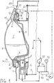
- a front-loading laundry drying machine formed in accordance with the present invention comprises a box-like body, generally made from enamelled sheet steel, in which all of the functional components are housed.
- the box-like body has a front 1, on which there is a control panel 20 and a filler opening closed by a loading door constituted by a generally circular metal frame 2 within which is housed a transparent porthole 3, generally made of glass, which is outwardly concave, that is, towards the front of the machine, which extends into the filler opening.
- a seal 4 fixed to the edge of the front opening, and for internal flow channelling ensures the seal between the door and the front of the machine.
- the door is hinged to the front in a conventional way, rotatable about a vertical axis, and is locked in the closed position by locking devices which are conventional and not illustrated.
- Opening the loading door gives access to a revolving drum 5 having a horizontal axis and being open at the front and rear, into which the laundry to be dried is placed.
- the revolving drum 5 is axially traversed by a flow of hot air which causes the liquid in the laundry to evaporate.
- the hot moist air leaves from the front of the drum 5 and is conveyed through a filter 6, which captures the fibres from the fabrics, to a condenser which is represented schematically by the block 51.
- the dehumidified air leaving the condenser 51 is driven by a fan 52, heated and recirculated to the revolving drum.
- the liquid condensate is collected in a vessel 53 of the condenser and conveyed by a pump 54 to a condensate collection chamber.
- a protective pressure switch 55 or equivalent level sensor detects the presence in the condensation vessel of liquid in excess of a predetermined level, and prevents the machine from functioning in the event of anomalies.
- the laundry drying machine is provided with a collection chamber 7 of a generally bi-convex lenticular shape, with an outer wall 9 and an inner wall 8 which is juxtaposed over the outer concave surface of the porthole 3 and extends to its edge to form an annular flange 10 which covers and surrounds the frame 2 of the door.
- the annular flange 10 extends in a crescent-shaped turnover portion 11 folded downwards to form a seat for the stable attachment and suspension of the chamber on the door frame.
- the front wall 9 by means of an appropriate downward fold close to the neck 12, forms an anatomical handle 15 which allows the chamber to be easily handled.
- the chamber 7 can be removed from the loading door, when the door is open, by a limited rotation of the chamber 7, represented by the arrow 16, about its upper support, which disengages the lower part of the flange 10 from the door frame 2.
- This rotation is followed by an upward movement which disengages the seat, formed by the crescent 11 and the flange 10, from the upper part of the frame 2.
- the crescent 11 is provided with one or more projections 17, 18 ( Figure 2) which are housed in a convenient recess in the front wall of the machine when the door is closed.
- the removal of the chamber 7 may be made safe by the interference of the control panel 20, which projects from the front, with the upper surface 21 of the inlet neck 12.
- the chamber 7 is filled with the liquid condensate, which is delivered to the chamber by a pump through a delivery pipe 22 and, through the inlet opening 13 ( Figure 2) to which the delivery pipe 22 is connected with an interposed normally-closed safety valve 23 which opens only when the chamber 7 is correctly installed on the door and the door is closed.
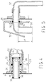
- Figure 4 is a scrap section of the same sectional view as Figure 1, showing a preferred embodiment of the safety valve 23.
- the valve is constituted by a generally cylindrical body 24 with a flange 25 for mounting on the front 1 of the machine.
- An axially movable valve shutter 26 is housed in the body 24, biased to the closed position by a compression spring 27.
- the spring 27 is compressed between a shoulder 28 of the body 24 and a shoulder 29 of the valve shutter which is, in its turn, resisted by the front 1 in the closed position.
- the internally hollow valve shutter 26 extends through an opening in the front 1 to form a nozzle 30 having a suitable resilient seal 31 at its end.
- valve shutter 26 is provided with radial apertures 32 which put the internal cavity of the valve shutter into communication with the outside.
- the cylindrical internal cavity is open at the nozzle end, and closed at the opposite end.
- An annular seal 33 mounted on the inner end of the valve shutter ensures the seal between the body 24 and the valve shutter 26 when the valve shutter is in the closed position.
- the delivery pipe 22 is connected to the sleeve 34.
- opening the door causes the immediate closure of the valve 23 and prevents possible escape of liquid from the pipe 22, even if the pump is in operation, thereby giving additional protection to that normally given by sensors which cause the machine to stop working if the door is not closed.
- valve 23 remains closed and, in this case also, there is no possibility of leakage from the pipe 22.
- the activation of the machine therefore results in liquid condensate accumulating in the condenser vessel and the intervention after a short time of the protective pressure switch, indicating an anomalous situation.
- the chamber 7 is provided with an overflow outlet and breather opening 14 ( Figure 2).
- the breather opening 14 is connected, when the chamber is installed in the door and the door is closed, to a nozzle 35 having a seal 36, mounted on the front 1 of the machine.
- the opening 14 of the chamber 7 advantageously opens into the chamber through a section of pipe 38, or filling column, extending downwards to a convenient depth P.
- the assembly comprising the pipe 38, the nozzle 35, and the pipe 37 forms a syphon with one arm (formed by the pipe 37) of greater length.
- the liquid returned from the chamber accumulates rapidly in the condenser vessel and causes the intervention, practically immediately, of the protective pressure switch.
- This arrangement also ensures that the level of liquid in the chamber 7 when the machine is stopped because of an anomalous condition, and the chamber is removed, is somewhat lower than the level of the filling opening and discharge outlet so as to prevent possible spillage caused by the rotation or agitation of the chamber when it is being moved.
- This arrangement also frees the positioning of the height of the filling opening from that of the breather outlet.
- the filling opening may be at a lower level than that of the overflow and breather opening as long as the pipe 38 extends into the chamber to a lower level than the filling pipe.
- an accumulation capacity in the order of 3.5 to 3.7 dm 3 can be easily and economically obtained.
- the capacity of the chamber may be increased without increasing the extent to which the chamber projects from the front of the machine, by providing an extension of the chamber below the frame 2 of the door and by having a rectangular rather than a lenticular chamber.
- the chamber may be made from an at least partially transparent plastics material to allow the level of liquid collected in the chamber to be seen.
Applications Claiming Priority (2)
| Application Number | Priority Date | Filing Date | Title |
|---|---|---|---|
| ITMI950657U | 1995-09-28 | ||
| IT1995MI000657U IT237177Y1 (it) | 1995-09-28 | 1995-09-28 | Asciugabiancheria a condensazione e caricamento frontale condispositivo di recupero della condensa in contenitore rimovibile |
Publications (2)
| Publication Number | Publication Date |
|---|---|
| EP0767268A1 true EP0767268A1 (de) | 1997-04-09 |
| EP0767268B1 EP0767268B1 (de) | 1999-12-08 |
Family
ID=11371156
Family Applications (1)
| Application Number | Title | Priority Date | Filing Date |
|---|---|---|---|
| EP96202159A Expired - Lifetime EP0767268B1 (de) | 1995-09-28 | 1996-07-31 | Frontladerwäschetrockner mit einem Kondensator mit abnehmbarer Kondensat-Sammelgefässvorrichtung |
Country Status (2)
| Country | Link |
|---|---|
| EP (1) | EP0767268B1 (de) |
| IT (1) | IT237177Y1 (de) |
Cited By (19)
| Publication number | Priority date | Publication date | Assignee | Title |
|---|---|---|---|---|
| EP1192888A1 (de) * | 2000-10-02 | 2002-04-03 | Brandt Cooking | Herausnehmbare Wasserbehälter, insbesondere für ein Dampfgargerät |
| EP1798324A1 (de) * | 2005-12-15 | 2007-06-20 | Brandt Industries SAS | Wäschetrockner mit Flüssigkeitsvorratsbehälter |
| EP1798325A1 (de) * | 2005-12-15 | 2007-06-20 | Brandt Industries SAS | Wäschetrockner mit Flüssigkeitsbehälter |
| EP1816252A1 (de) * | 2006-02-01 | 2007-08-08 | BSH Bosch und Siemens Hausgeräte GmbH | Anordnung eines Kondensatbehälters in einem Haushalt-Wäschetrockner und Sensorsystem dafür |
| EP1905883A1 (de) * | 2006-09-29 | 2008-04-02 | Electrolux Home Products Corporation N.V. | Wäschetrockner mit einem in der Tür montierten Kondensatsammelbehälter |
| EP1975302A1 (de) | 2007-03-27 | 2008-10-01 | FagorBrandt SAS | Wäschetrockner, der einen hydraulischen Schaltkreis in der Tür zur Versorgung eines Dampfergenerators umfasst |
| EP2128328A1 (de) * | 2008-05-29 | 2009-12-02 | Electrolux Home Products Corporation N.V. | Wäschetrockner |
| ITMI20101401A1 (it) * | 2010-07-28 | 2012-01-29 | Candy Spa | Macchina asciuga-biancheria. |
| EP2412867A1 (de) * | 2010-07-28 | 2012-02-01 | Candy S.p.A. | Wäschetrocknermaschine |
| ITTO20100916A1 (it) * | 2010-11-19 | 2012-05-20 | Indesit Co Spa | Macchina asciugatrice comprendente un contenitore per la raccolta di acqua di condensa, e relativo contenitore. |
| DE102011082253A1 (de) * | 2011-09-07 | 2013-03-07 | BSH Bosch und Siemens Hausgeräte GmbH | Wäschetrocknungsgerät |
| EP2574696A1 (de) * | 2011-09-28 | 2013-04-03 | Electrolux Home Products Corporation N.V. | Wäschetrockner unfassend ein Kondensatspeicherbehälter |
| EP2455539A3 (de) * | 2010-11-19 | 2013-06-12 | Indesit Company S.p.A. | Behälter zum Sammeln des Kondenswassers in einem Wäschetrockner und Wäschetrockner damit |
| DE102014217355A1 (de) | 2014-08-29 | 2016-03-03 | BSH Hausgeräte GmbH | Fluidanschlussvorrichtung für ein Haushaltsgerät, sowie Haushaltsgerät mit einer solchen |
| CN105603702A (zh) * | 2014-11-25 | 2016-05-25 | 青岛海尔洗衣机有限公司 | 一种干衣机集水盒及干衣机 |
| CN106192326A (zh) * | 2015-04-30 | 2016-12-07 | 无锡小天鹅股份有限公司 | 干衣机 |
| JP2018526086A (ja) * | 2015-08-17 | 2018-09-13 | エルジー エレクトロニクス インコーポレイティド | 乾燥機 |
| CN108823923A (zh) * | 2018-07-10 | 2018-11-16 | 长虹美菱股份有限公司 | 一种具备门体空腔存储冷凝水功能的干衣机 |
| CN110761051A (zh) * | 2019-11-04 | 2020-02-07 | 安徽欧斯福科技有限公司 | 一种烘干机前门板可视储水系统 |
Citations (4)
| Publication number | Priority date | Publication date | Assignee | Title |
|---|---|---|---|---|
| GB2115127A (en) * | 1982-02-09 | 1983-09-01 | Bosch Siemens Hausgeraete | Household laundry drier with condensate collection |
| GB2115126A (en) * | 1982-02-09 | 1983-09-01 | Bosch Siemens Hausgeraete | Household laundry drier with condensate collection |
| EP0254018A1 (de) * | 1986-07-25 | 1988-01-27 | INDUSTRIE ZANUSSI S.p.A. | Wäschetrockner mit Kondensationseinrichtung |
| EP0484225A1 (de) * | 1990-11-02 | 1992-05-06 | Ciapem | Wäschetrockner mit einem Kondensatsammelbehälter |
-
1995
- 1995-09-28 IT IT1995MI000657U patent/IT237177Y1/it active IP Right Grant
-
1996
- 1996-07-31 EP EP96202159A patent/EP0767268B1/de not_active Expired - Lifetime
Patent Citations (4)
| Publication number | Priority date | Publication date | Assignee | Title |
|---|---|---|---|---|
| GB2115127A (en) * | 1982-02-09 | 1983-09-01 | Bosch Siemens Hausgeraete | Household laundry drier with condensate collection |
| GB2115126A (en) * | 1982-02-09 | 1983-09-01 | Bosch Siemens Hausgeraete | Household laundry drier with condensate collection |
| EP0254018A1 (de) * | 1986-07-25 | 1988-01-27 | INDUSTRIE ZANUSSI S.p.A. | Wäschetrockner mit Kondensationseinrichtung |
| EP0484225A1 (de) * | 1990-11-02 | 1992-05-06 | Ciapem | Wäschetrockner mit einem Kondensatsammelbehälter |
Cited By (27)
| Publication number | Priority date | Publication date | Assignee | Title |
|---|---|---|---|---|
| EP1192888A1 (de) * | 2000-10-02 | 2002-04-03 | Brandt Cooking | Herausnehmbare Wasserbehälter, insbesondere für ein Dampfgargerät |
| FR2814734A1 (fr) * | 2000-10-02 | 2002-04-05 | Brandt Cooking | Reservoir d'eau amovible, notamment pour un four de cuisson a la vapeur |
| EP1798324A1 (de) * | 2005-12-15 | 2007-06-20 | Brandt Industries SAS | Wäschetrockner mit Flüssigkeitsvorratsbehälter |
| EP1798325A1 (de) * | 2005-12-15 | 2007-06-20 | Brandt Industries SAS | Wäschetrockner mit Flüssigkeitsbehälter |
| FR2894995A1 (fr) * | 2005-12-15 | 2007-06-22 | Brandt Ind Sas | Reservoir de liquide, notamment pour appareil electromenager de type seche-linge |
| EP1816252A1 (de) * | 2006-02-01 | 2007-08-08 | BSH Bosch und Siemens Hausgeräte GmbH | Anordnung eines Kondensatbehälters in einem Haushalt-Wäschetrockner und Sensorsystem dafür |
| EP1905883A1 (de) * | 2006-09-29 | 2008-04-02 | Electrolux Home Products Corporation N.V. | Wäschetrockner mit einem in der Tür montierten Kondensatsammelbehälter |
| WO2008037399A1 (en) * | 2006-09-29 | 2008-04-03 | Electrolux Home Products Corporation N.V. | Laundry drier with a door-mounted condensation tank |
| EP1975302A1 (de) | 2007-03-27 | 2008-10-01 | FagorBrandt SAS | Wäschetrockner, der einen hydraulischen Schaltkreis in der Tür zur Versorgung eines Dampfergenerators umfasst |
| FR2914322A1 (fr) * | 2007-03-27 | 2008-10-03 | Brandt Ind Sas | Machine a secher le linge comprenant un circuit hydraulique dans la porte pour alimenter un generateur de vapeur |
| EP2128328A1 (de) * | 2008-05-29 | 2009-12-02 | Electrolux Home Products Corporation N.V. | Wäschetrockner |
| EP2522771A3 (de) * | 2008-05-29 | 2014-08-27 | Electrolux Home Products Corporation N.V. | Wäschetrockner |
| EP2522771A2 (de) * | 2008-05-29 | 2012-11-14 | Electrolux Home Products Corporation N.V. | Wäschetrockner |
| RU2516945C2 (ru) * | 2008-05-29 | 2014-05-20 | Электролюкс Хоум Продактс Корпорейшн Н.В. | Сушильная машина для белья |
| EP2412867A1 (de) * | 2010-07-28 | 2012-02-01 | Candy S.p.A. | Wäschetrocknermaschine |
| ITMI20101401A1 (it) * | 2010-07-28 | 2012-01-29 | Candy Spa | Macchina asciuga-biancheria. |
| EP2455538A1 (de) * | 2010-11-19 | 2012-05-23 | Indesit Company S.p.A. | Wäschetrockner mit einem Behälter für Kondenswasser und Behälter |
| EP2455539A3 (de) * | 2010-11-19 | 2013-06-12 | Indesit Company S.p.A. | Behälter zum Sammeln des Kondenswassers in einem Wäschetrockner und Wäschetrockner damit |
| ITTO20100916A1 (it) * | 2010-11-19 | 2012-05-20 | Indesit Co Spa | Macchina asciugatrice comprendente un contenitore per la raccolta di acqua di condensa, e relativo contenitore. |
| DE102011082253A1 (de) * | 2011-09-07 | 2013-03-07 | BSH Bosch und Siemens Hausgeräte GmbH | Wäschetrocknungsgerät |
| EP2574696A1 (de) * | 2011-09-28 | 2013-04-03 | Electrolux Home Products Corporation N.V. | Wäschetrockner unfassend ein Kondensatspeicherbehälter |
| DE102014217355A1 (de) | 2014-08-29 | 2016-03-03 | BSH Hausgeräte GmbH | Fluidanschlussvorrichtung für ein Haushaltsgerät, sowie Haushaltsgerät mit einer solchen |
| CN105603702A (zh) * | 2014-11-25 | 2016-05-25 | 青岛海尔洗衣机有限公司 | 一种干衣机集水盒及干衣机 |
| CN106192326A (zh) * | 2015-04-30 | 2016-12-07 | 无锡小天鹅股份有限公司 | 干衣机 |
| JP2018526086A (ja) * | 2015-08-17 | 2018-09-13 | エルジー エレクトロニクス インコーポレイティド | 乾燥機 |
| CN108823923A (zh) * | 2018-07-10 | 2018-11-16 | 长虹美菱股份有限公司 | 一种具备门体空腔存储冷凝水功能的干衣机 |
| CN110761051A (zh) * | 2019-11-04 | 2020-02-07 | 安徽欧斯福科技有限公司 | 一种烘干机前门板可视储水系统 |
Also Published As
| Publication number | Publication date |
|---|---|
| ITMI950657U1 (it) | 1997-03-28 |
| ITMI950657V0 (de) | 1995-09-28 |
| EP0767268B1 (de) | 1999-12-08 |
| IT237177Y1 (it) | 2000-08-31 |
Similar Documents
| Publication | Publication Date | Title |
|---|---|---|
| EP0767268B1 (de) | Frontladerwäschetrockner mit einem Kondensator mit abnehmbarer Kondensat-Sammelgefässvorrichtung | |
| EP2317005B1 (de) | Haushaltsgerät mit Wasserbehälter | |
| ITMI960095U1 (it) | Asciugabiancheria con sportello frontale a pannello e serbatoio estraibile di recupero dell'acqua di condensa | |
| CN108866922A (zh) | 一种滚筒洗衣机 | |
| KR20060040352A (ko) | 린트 필터 어셈블리가 장착된 건조 세탁기 | |
| US6584812B1 (en) | Washing machine with a drain pump | |
| EP0731204B1 (de) | Wäschetrockner mit Kondensationseinrichtung mit Kondensat-Sammelgefässvorrichtung | |
| EP0731203A1 (de) | Wäschetrockner mit Kondensationseinrichtung mit Kondensat-Sammelgefässvorrichtung | |
| ITMI950454A1 (it) | Asciugabiancheria a condensazione con recupero di condensa in contenitore | |
| JP4666520B2 (ja) | ドラム式洗濯乾燥機 | |
| EP2412867B1 (de) | Wäschetrocknermaschine | |
| EP1674607B1 (de) | Wäschetrockner | |
| EP1674837B1 (de) | Wäschetrockner | |
| KR102053585B1 (ko) | 음식물 쓰레기 수거장치 | |
| EP0221584B1 (de) | Maschine zum Waschen und Trocknen von Wäsche | |
| EP3124683B1 (de) | Wäschetrockner | |
| ITMI950712U1 (it) | Macchina asciugabiancheria a condensazione e caricamento frontale con serbatoio rimovibile di recupero condensa formato nel portello | |
| CN111041779A (zh) | 一种滚筒洗衣机 | |
| CA2271701C (en) | Washing machine | |
| CN113718484A (zh) | 一种滚筒洗衣机 | |
| WO2000061854A1 (en) | Laundry machine | |
| KR20050063118A (ko) | 건조기의 응축수 배관구조 | |
| KR20040011967A (ko) | 이물채집통을 구비한 드럼세탁기 | |
| JPH0535085U (ja) | 洗濯機の洗剤供給装置 | |
| JPS63206279A (ja) | 全自動洗濯機 |
Legal Events
| Date | Code | Title | Description |
|---|---|---|---|
| PUAI | Public reference made under article 153(3) epc to a published international application that has entered the european phase |
Free format text: ORIGINAL CODE: 0009012 |
|
| AK | Designated contracting states |
Kind code of ref document: A1 Designated state(s): GB IT |
|
| 17P | Request for examination filed |
Effective date: 19970227 |
|
| GRAG | Despatch of communication of intention to grant |
Free format text: ORIGINAL CODE: EPIDOS AGRA |
|
| 17Q | First examination report despatched |
Effective date: 19990331 |
|
| GRAG | Despatch of communication of intention to grant |
Free format text: ORIGINAL CODE: EPIDOS AGRA |
|
| GRAH | Despatch of communication of intention to grant a patent |
Free format text: ORIGINAL CODE: EPIDOS IGRA |
|
| GRAH | Despatch of communication of intention to grant a patent |
Free format text: ORIGINAL CODE: EPIDOS IGRA |
|
| GRAA | (expected) grant |
Free format text: ORIGINAL CODE: 0009210 |
|
| AK | Designated contracting states |
Kind code of ref document: B1 Designated state(s): GB IT |
|
| ITF | It: translation for a ep patent filed |
Owner name: JACOBACCI & PERANI S.P.A. |
|
| PLBE | No opposition filed within time limit |
Free format text: ORIGINAL CODE: 0009261 |
|
| STAA | Information on the status of an ep patent application or granted ep patent |
Free format text: STATUS: NO OPPOSITION FILED WITHIN TIME LIMIT |
|
| 26N | No opposition filed | ||
| REG | Reference to a national code |
Ref country code: GB Ref legal event code: IF02 |
|
| PGFP | Annual fee paid to national office [announced via postgrant information from national office to epo] |
Ref country code: GB Payment date: 20060713 Year of fee payment: 11 |
|
| PGFP | Annual fee paid to national office [announced via postgrant information from national office to epo] |
Ref country code: IT Payment date: 20060731 Year of fee payment: 11 |
|
| GBPC | Gb: european patent ceased through non-payment of renewal fee |
Effective date: 20070731 |
|
| PG25 | Lapsed in a contracting state [announced via postgrant information from national office to epo] |
Ref country code: GB Free format text: LAPSE BECAUSE OF NON-PAYMENT OF DUE FEES Effective date: 20070731 |
|
| PG25 | Lapsed in a contracting state [announced via postgrant information from national office to epo] |
Ref country code: IT Free format text: LAPSE BECAUSE OF NON-PAYMENT OF DUE FEES Effective date: 20070731 |