EP0766349B1 - Anschlussvorrichtung für die Telekommunikations- und Datentechnik - Google Patents
Anschlussvorrichtung für die Telekommunikations- und Datentechnik Download PDFInfo
- Publication number
- EP0766349B1 EP0766349B1 EP96110940A EP96110940A EP0766349B1 EP 0766349 B1 EP0766349 B1 EP 0766349B1 EP 96110940 A EP96110940 A EP 96110940A EP 96110940 A EP96110940 A EP 96110940A EP 0766349 B1 EP0766349 B1 EP 0766349B1
- Authority
- EP
- European Patent Office
- Prior art keywords
- webs
- wire guide
- web panels
- guide part
- strip
- Prior art date
- Legal status (The legal status is an assumption and is not a legal conclusion. Google has not performed a legal analysis and makes no representation as to the accuracy of the status listed.)
- Expired - Lifetime
Links
- 238000005516 engineering process Methods 0.000 claims description 5
- 238000001465 metallisation Methods 0.000 claims description 4
- 238000012216 screening Methods 0.000 claims 3
- 239000004020 conductor Substances 0.000 claims 1
- 238000003780 insertion Methods 0.000 claims 1
- 230000037431 insertion Effects 0.000 claims 1
- 238000010276 construction Methods 0.000 description 5
- 230000015572 biosynthetic process Effects 0.000 description 1
- 210000001061 forehead Anatomy 0.000 description 1
- 238000012856 packing Methods 0.000 description 1
Images



Classifications
-
- H—ELECTRICITY
- H01—ELECTRIC ELEMENTS
- H01R—ELECTRICALLY-CONDUCTIVE CONNECTIONS; STRUCTURAL ASSOCIATIONS OF A PLURALITY OF MUTUALLY-INSULATED ELECTRICAL CONNECTING ELEMENTS; COUPLING DEVICES; CURRENT COLLECTORS
- H01R13/00—Details of coupling devices of the kinds covered by groups H01R12/70 or H01R24/00 - H01R33/00
- H01R13/648—Protective earth or shield arrangements on coupling devices, e.g. anti-static shielding
- H01R13/658—High frequency shielding arrangements, e.g. against EMI [Electro-Magnetic Interference] or EMP [Electro-Magnetic Pulse]
- H01R13/6591—Specific features or arrangements of connection of shield to conductive members
- H01R13/6592—Specific features or arrangements of connection of shield to conductive members the conductive member being a shielded cable
-
- H—ELECTRICITY
- H01—ELECTRIC ELEMENTS
- H01R—ELECTRICALLY-CONDUCTIVE CONNECTIONS; STRUCTURAL ASSOCIATIONS OF A PLURALITY OF MUTUALLY-INSULATED ELECTRICAL CONNECTING ELEMENTS; COUPLING DEVICES; CURRENT COLLECTORS
- H01R13/00—Details of coupling devices of the kinds covered by groups H01R12/70 or H01R24/00 - H01R33/00
- H01R13/648—Protective earth or shield arrangements on coupling devices, e.g. anti-static shielding
- H01R13/658—High frequency shielding arrangements, e.g. against EMI [Electro-Magnetic Interference] or EMP [Electro-Magnetic Pulse]
- H01R13/6581—Shield structure
- H01R13/6582—Shield structure with resilient means for engaging mating connector
Definitions
- the invention relates to a connection device for telecommunications and data technology according to the features of the preamble of claim 1.
- a connection device of the generic type is previously known from DE 43 03 976 C1. With this it is Wire guide part of the last holder from five together connected by a V-shaped trough plate Web plates formed and between two end plates of the separate base part, in which four Cross guides for inserting metallized Cable holders are formed. These are on both Sides with locking clips for inserting with locking lugs provided individual shield plates formed by which have four shield plates on each side of the Ledge holders are provided between each two adjacent webs of the total of five web plates to grab.
- In the receiving trough of the wire guide part is one with a plurality of contact elements equipped terminal block inserted.
- the known connecting device is particularly used in distribution cabinets with 19 "fixed frames, into the eight side-by-side connection devices fit for four shielded cables each, so that a total of 32 ports side by side in one Fit 19 "rack.
- the disadvantage here is those for modern telecommunications and data technology insufficient density of the ports in a 19 "rack, since the construction volume of the known connecting devices is relatively large.
- Another disadvantage is that the previously known connection device from a variety of Individual parts exist, so that the assembly is complex is. A front panel, a connector strip, a base part, a wire guide part, four Cable holder and eight shielding plates available, so that a total of 16 individual parts are to be assembled.
- connection device in terms of assembly too simplify and reduce the construction volume.
- Base part and wire guide part existing strip holder integrally formed and the front panel is on the two end web plates of the wire guide part open and the connector between the webs of snapped onto both end web plates. Furthermore, the Web of the two end web plates of the wire guide part a one-piece shield plate on that on both sides of the between the face plates located web plates is arranged. This will the number of components on only five components and thus significantly reduced. Furthermore, the front panel snapped directly onto the forehead plate, which significantly simplifies the Assembly effort results. This also will Construction volume of the connection device reduced.
- the entire surface of the last holder made of plastic provided with an electrically conductive metallization, so that in the prior art connection device required metallized cable holder are more necessary.
- the shielding of the braid provided cable is immediately in conductive Connection with the metallization of the last holder, on each of which a shield plate is attached and is contacted.
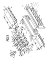
- Connection device for telecommunication and data technology includes a terminal block 2, two Shield plates 3, a strip holder 5 from a U-shaped Wire guide part 6 with four web plates 7 and two end web plates 8 and a base part 10.
- the Last holder 5 is made up of the base part 10 and the Wire guide part 6 molded in one piece from plastic.
- the surface of the strip holder 5 is electrical metallized conductive.
- the last holder 5 can together with the connector 2 used molded clamping pieces 11, 12 on not shown, parallel rails can be snapped on.
- a snap-on front panel 13 closes the connection device from. Through a rectangular opening 14 in the front panel 13 are plugs 15 by means of tabs 16 can be inserted into the terminal strip 2.
- the one-piece made of plastic and electrical metallized strip holder 5 includes in its wire guide part 6 four at a distance from each other located web plates 7, the base 17 of each protrudes the base part 10 and their lateral webs 18 the bottom part of the terminal block 2 on both sides enclose between themselves.
- the free ends of the Web 18 of the web plates 7 are for the formation of spring arms 19 slotted, the spring arms 19 spring the shield plates 3. center between the webs 18 there are support webs 20 for support the rear 21 of the terminal block 2, the support webs 20 of the two middle web plates 7 with recesses 22 for engaging one on the Back 21 of the terminal block 2 molded wire guide bracket 23 are provided.
- the end wall plates 8 on the two end faces Ends of the wire guide part 6 are with two lateral Provide webs 26 between which the connection bar 2 is engaged.
- the free ends of the webs 26 are with latching devices 25 from receiving openings 28 and in this trained hook lugs 29 for snapping the front panel 13 provided.
- the locking devices 24 of the front panel 13 consist of Rear arranged webs 27, which in the receiving openings 28 and engage behind the hook lugs 29. This way, the total of four under the front plate 13 molded hook webs 27 a Locking the front panel 13 with the strip holder 5 cause.
- Installed in pairs between the ends Hook bars 27 are on the underside of the front panel 13 parallel guide webs 30 formed, the intervene in the terminal block 2 to secure the position.
- the terminal block 2 is with the over the back 21 protruding clamps 12 and the last holder 5 with the correspondingly adapted clamping pieces 11 for Clamp on the bar profiles, not shown Mistake.
- the clamping pieces 11 are on the undersides the webs 26 of the end web plates 8 of the last holder 5 arranged. Due to the one-piece design of the Last holder 5 from wire guide part 6 and base part 10 the end web plates 8 also form the end plates 24 of the base part 10.
- This has one five cable entries 31 formed rear wall 32, the cable entries 31 being spatially offset from one another are arranged alternately (Fig. 5).
- conical cable holders 33 can be locked by means of interlocking catches 34, through which the five multi-core, shielded cables 35 are introduced, the shield 36 around the tapered ends of the cable holder 33 and with the metallized surface of the last holder 5 is brought into electrically conductive connection.
- the individual cable cores 37 are between two web plates 7 or a web plate 7 and a front web plate 8 led to the terminal block 2, in one Plurality of contact elements, not shown, for Connection of the cable wires 37 of the five, with braided shield 36 provided cable 35 is arranged.
- the single ones Cables 35 are in a manner not shown the associated contact elements connected.
- each shield plate 3 On each side of the wire guide part 6 of the last holder 5 is a shield plate 3 by means of molded Locking lugs 38 in locking brackets 9 on the wire guide part 5 stored and by means of further locking elements 39 with Lugs 4 on the inside of the end plate 8 locked.
- Each one-piece metallic shield plate 3 has a plate-shaped central part 40 which extends between the two end web plates 8 and directly on the spring arms 19 of the webs 18 of the Web plates 7 comes resiliently to the system.
- the free The end face of each shield plate 3 is five Groups of three alternating in opposite directions curved screen taps 41, which over the Front of the terminal block 2 through the opening 14 protrude in the front panel 13 and with appropriate Screen taps 42 of the connector 15 in conductive Can be connected.
- connection device is for easy assembly from only five individual parts, namely the front plate 13, the terminal block 2, the strip holder 5 and the two Shield plates 3.
- the electrically conductive metallization of the strip holder 5 causes the shield the contact elements located in the terminal strip 2 from the shield braid of the five cables fed 35 over the two side shield plates 3 without interruption forwarded to the shielding of the connector 15 is so that a potential equalization takes place.
Landscapes
- Details Of Connecting Devices For Male And Female Coupling (AREA)
- Telephonic Communication Services (AREA)
Applications Claiming Priority (2)
| Application Number | Priority Date | Filing Date | Title |
|---|---|---|---|
| DE19537531 | 1995-09-29 | ||
| DE19537531A DE19537531C1 (de) | 1995-09-29 | 1995-09-29 | Anschlußvorrichtung für die Telekommunikations- und Datentechnik |
Publications (3)
| Publication Number | Publication Date |
|---|---|
| EP0766349A2 EP0766349A2 (de) | 1997-04-02 |
| EP0766349A3 EP0766349A3 (https=) | 1997-05-07 |
| EP0766349B1 true EP0766349B1 (de) | 2000-09-13 |
Family
ID=7774372
Family Applications (1)
| Application Number | Title | Priority Date | Filing Date |
|---|---|---|---|
| EP96110940A Expired - Lifetime EP0766349B1 (de) | 1995-09-29 | 1996-07-06 | Anschlussvorrichtung für die Telekommunikations- und Datentechnik |
Country Status (3)
| Country | Link |
|---|---|
| EP (1) | EP0766349B1 (https=) |
| AT (1) | ATE196388T1 (https=) |
| DE (2) | DE19537531C1 (https=) |
Families Citing this family (2)
| Publication number | Priority date | Publication date | Assignee | Title |
|---|---|---|---|---|
| DE10001553A1 (de) * | 2000-01-14 | 2001-08-02 | Krone Gmbh | Vorrichtung zur Schirmung für Anschlussleisten |
| DE202011100540U1 (de) | 2011-05-11 | 2011-06-22 | 3M Innovative Properties Co., Minn. | Anschlussvorrichtung |
Family Cites Families (4)
| Publication number | Priority date | Publication date | Assignee | Title |
|---|---|---|---|---|
| DE3888333T2 (de) * | 1987-12-21 | 1994-09-08 | Whitaker Corp | Zusammenbau zum Datenverteilen. |
| JPH0334275A (ja) * | 1989-06-30 | 1991-02-14 | Toshiba Lighting & Technol Corp | 接続器具 |
| FR2679405B1 (fr) * | 1991-07-17 | 1994-01-07 | Pouyet International | Reglette d'interconnexion, en particulier pour lignes telephoniques ou informatiques. |
| DE4303976C1 (de) * | 1993-02-08 | 1994-02-17 | Krone Ag | Anschlußvorrichtung für die Kommunikations- und Datentechnik |
-
1995
- 1995-09-29 DE DE19537531A patent/DE19537531C1/de not_active Expired - Fee Related
-
1996
- 1996-07-06 AT AT96110940T patent/ATE196388T1/de not_active IP Right Cessation
- 1996-07-06 EP EP96110940A patent/EP0766349B1/de not_active Expired - Lifetime
- 1996-07-06 DE DE59605871T patent/DE59605871D1/de not_active Expired - Fee Related
Also Published As
| Publication number | Publication date |
|---|---|
| DE19537531C1 (de) | 1997-02-06 |
| EP0766349A3 (https=) | 1997-05-07 |
| DE59605871D1 (de) | 2000-10-19 |
| EP0766349A2 (de) | 1997-04-02 |
| ATE196388T1 (de) | 2000-09-15 |
Similar Documents
| Publication | Publication Date | Title |
|---|---|---|
| DE2811812C2 (de) | Kabelendeinrichtung der Fernmeldelinientechnik | |
| EP0847106B1 (de) | Anschluss-, Trenn- oder Schaltleiste | |
| DE4440455C2 (de) | Montagevorrichtung für RJ-Verbindungselemente der Nachrichten- und Datentechnik (Patch-Panel) | |
| EP0766482A2 (de) | Verteilereinrichtung für die Telekommunikations- und Datentechnik | |
| EP1915876B1 (de) | Montagevorrichtung für leitungs- und steckverbindungselemente | |
| DE102007032578A1 (de) | Anschlussmodul für die Telekommunikations- und Datentechnik | |
| EP0794590B1 (de) | Anschlussmodul für die Telekommunikationstechnik | |
| DE102007032579A1 (de) | Endverschluss für die Telekommunikations- und Datentechnik | |
| EP0766349B1 (de) | Anschlussvorrichtung für die Telekommunikations- und Datentechnik | |
| DE19511284C1 (de) | Geräteadapter für Stromsammelschienen eines Sammelschienensystems | |
| EP0374401B1 (de) | Anordnung zum geordneten Führen von Kabelenden | |
| EP1005235A2 (de) | Vorrichtung zum Befestigen moduler Mehrfach-Anchlussleisten an parallelen Trägerelementen eines Verteilergestells einer Telefonzentrale o. dgl. | |
| DE19537529C1 (de) | Verteilerleiste für die Telekommunikations- und Datentechnik | |
| DE19935445C1 (de) | Baustein für den Einbau in ein Gehäuse eines elektrischen Verteilers | |
| DE102007032577A1 (de) | Endverschluss für die Telekommunikations- und Datentechnik | |
| EP3885648B1 (de) | System zur bereitstellung einer leuchte mit elektrischem abgriff umfassend eine durchgangskontakteinrichtung | |
| DE4303976C1 (de) | Anschlußvorrichtung für die Kommunikations- und Datentechnik | |
| DE1512787C3 (de) | Schalt- und Trennleiste für Fernmeldeanlagen, insbesondere für Rangierfelder in Fernsprechvermittlungsanlagen | |
| DE19711102C2 (de) | Vorrichtung zur Potentialführung von geschirmten Kabeln in Verteilereinrichtungen der Telekommunikations- und Datentechnik | |
| DE4336079A1 (de) | Führungselement für Lichtwellenleiter | |
| DE3027936C2 (de) | Verteilergestell für die Nachrichtenübertragungstechnik | |
| DE69633107T2 (de) | Abzweigdose mit Mitteln zur mechanischen Führung von Kabeln | |
| DE19537530C1 (de) | Datenanschlußdose für hohe Übertragungsraten | |
| DE29515983U1 (de) | Montagebügel | |
| DE2315485C3 (de) | NF-Verteilergestell für Einrichtungen der Nachrichtenübertragungstechnik |
Legal Events
| Date | Code | Title | Description |
|---|---|---|---|
| PUAI | Public reference made under article 153(3) epc to a published international application that has entered the european phase |
Free format text: ORIGINAL CODE: 0009012 |
|
| PUAL | Search report despatched |
Free format text: ORIGINAL CODE: 0009013 |
|
| AK | Designated contracting states |
Kind code of ref document: A2 Designated state(s): AT BE CH DE DK ES FI FR GB GR IE IT LI NL PT SE |
|
| AK | Designated contracting states |
Kind code of ref document: A3 Designated state(s): AT BE CH DE DK ES FI FR GB GR IE IT LI NL PT SE |
|
| 17P | Request for examination filed |
Effective date: 19970407 |
|
| 17Q | First examination report despatched |
Effective date: 19990414 |
|
| GRAG | Despatch of communication of intention to grant |
Free format text: ORIGINAL CODE: EPIDOS AGRA |
|
| GRAG | Despatch of communication of intention to grant |
Free format text: ORIGINAL CODE: EPIDOS AGRA |
|
| GRAH | Despatch of communication of intention to grant a patent |
Free format text: ORIGINAL CODE: EPIDOS IGRA |
|
| 17Q | First examination report despatched |
Effective date: 19990414 |
|
| GRAH | Despatch of communication of intention to grant a patent |
Free format text: ORIGINAL CODE: EPIDOS IGRA |
|
| RAP1 | Party data changed (applicant data changed or rights of an application transferred) |
Owner name: KRONE GMBH |
|
| GRAA | (expected) grant |
Free format text: ORIGINAL CODE: 0009210 |
|
| AK | Designated contracting states |
Kind code of ref document: B1 Designated state(s): AT BE CH DE DK ES FI FR GB GR IE IT LI NL PT SE |
|
| PG25 | Lapsed in a contracting state [announced via postgrant information from national office to epo] |
Ref country code: NL Free format text: LAPSE BECAUSE OF FAILURE TO SUBMIT A TRANSLATION OF THE DESCRIPTION OR TO PAY THE FEE WITHIN THE PRESCRIBED TIME-LIMIT Effective date: 20000913 Ref country code: IT Free format text: LAPSE BECAUSE OF FAILURE TO SUBMIT A TRANSLATION OF THE DESCRIPTION OR TO PAY THE FEE WITHIN THE PRE;WARNING: LAPSES OF ITALIAN PATENTS WITH EFFECTIVE DATE BEFORE 2007 MAY HAVE OCCURRED AT ANY TIME BEFORE 2007. THE CORRECT EFFECTIVE DATE MAY BE DIFFERENT FROM THE ONE RECORDED.SCRIBED TIME-LIMIT Effective date: 20000913 Ref country code: GB Free format text: LAPSE BECAUSE OF FAILURE TO SUBMIT A TRANSLATION OF THE DESCRIPTION OR TO PAY THE FEE WITHIN THE PRESCRIBED TIME-LIMIT Effective date: 20000913 Ref country code: FR Free format text: LAPSE BECAUSE OF FAILURE TO SUBMIT A TRANSLATION OF THE DESCRIPTION OR TO PAY THE FEE WITHIN THE PRESCRIBED TIME-LIMIT Effective date: 20000913 Ref country code: FI Free format text: LAPSE BECAUSE OF FAILURE TO SUBMIT A TRANSLATION OF THE DESCRIPTION OR TO PAY THE FEE WITHIN THE PRESCRIBED TIME-LIMIT Effective date: 20000913 Ref country code: ES Free format text: THE PATENT HAS BEEN ANNULLED BY A DECISION OF A NATIONAL AUTHORITY Effective date: 20000913 |
|
| REF | Corresponds to: |
Ref document number: 196388 Country of ref document: AT Date of ref document: 20000915 Kind code of ref document: T |
|
| REG | Reference to a national code |
Ref country code: CH Ref legal event code: EP |
|
| REF | Corresponds to: |
Ref document number: 59605871 Country of ref document: DE Date of ref document: 20001019 |
|
| REG | Reference to a national code |
Ref country code: IE Ref legal event code: FG4D Free format text: GERMAN |
|
| PG25 | Lapsed in a contracting state [announced via postgrant information from national office to epo] |
Ref country code: SE Free format text: LAPSE BECAUSE OF FAILURE TO SUBMIT A TRANSLATION OF THE DESCRIPTION OR TO PAY THE FEE WITHIN THE PRESCRIBED TIME-LIMIT Effective date: 20001213 Ref country code: PT Free format text: LAPSE BECAUSE OF FAILURE TO SUBMIT A TRANSLATION OF THE DESCRIPTION OR TO PAY THE FEE WITHIN THE PRESCRIBED TIME-LIMIT Effective date: 20001213 Ref country code: DK Free format text: LAPSE BECAUSE OF FAILURE TO SUBMIT A TRANSLATION OF THE DESCRIPTION OR TO PAY THE FEE WITHIN THE PRESCRIBED TIME-LIMIT Effective date: 20001213 |
|
| PG25 | Lapsed in a contracting state [announced via postgrant information from national office to epo] |
Ref country code: GR Free format text: LAPSE BECAUSE OF FAILURE TO SUBMIT A TRANSLATION OF THE DESCRIPTION OR TO PAY THE FEE WITHIN THE PRESCRIBED TIME-LIMIT Effective date: 20001215 |
|
| NLV1 | Nl: lapsed or annulled due to failure to fulfill the requirements of art. 29p and 29m of the patents act | ||
| EN | Fr: translation not filed | ||
| GBV | Gb: ep patent (uk) treated as always having been void in accordance with gb section 77(7)/1977 [no translation filed] |
Effective date: 20000913 |
|
| PG25 | Lapsed in a contracting state [announced via postgrant information from national office to epo] |
Ref country code: IE Free format text: LAPSE BECAUSE OF NON-PAYMENT OF DUE FEES Effective date: 20010419 |
|
| REG | Reference to a national code |
Ref country code: IE Ref legal event code: FD4D |
|
| PG25 | Lapsed in a contracting state [announced via postgrant information from national office to epo] |
Ref country code: AT Free format text: LAPSE BECAUSE OF NON-PAYMENT OF DUE FEES Effective date: 20010706 |
|
| PLBE | No opposition filed within time limit |
Free format text: ORIGINAL CODE: 0009261 |
|
| STAA | Information on the status of an ep patent application or granted ep patent |
Free format text: STATUS: NO OPPOSITION FILED WITHIN TIME LIMIT |
|
| PG25 | Lapsed in a contracting state [announced via postgrant information from national office to epo] |
Ref country code: LI Free format text: LAPSE BECAUSE OF NON-PAYMENT OF DUE FEES Effective date: 20010731 Ref country code: CH Free format text: LAPSE BECAUSE OF NON-PAYMENT OF DUE FEES Effective date: 20010731 Ref country code: BE Free format text: LAPSE BECAUSE OF NON-PAYMENT OF DUE FEES Effective date: 20010731 |
|
| PGFP | Annual fee paid to national office [announced via postgrant information from national office to epo] |
Ref country code: DE Payment date: 20010808 Year of fee payment: 6 |
|
| 26N | No opposition filed | ||
| BERE | Be: lapsed |
Owner name: KRONE G.M.B.H. Effective date: 20010731 |
|
| REG | Reference to a national code |
Ref country code: CH Ref legal event code: PL |
|
| PG25 | Lapsed in a contracting state [announced via postgrant information from national office to epo] |
Ref country code: DE Free format text: LAPSE BECAUSE OF NON-PAYMENT OF DUE FEES Effective date: 20030201 |