EP0765694B1 - Nozzle coating method and equipment - Google Patents
Nozzle coating method and equipment Download PDFInfo
- Publication number
- EP0765694B1 EP0765694B1 EP96115179A EP96115179A EP0765694B1 EP 0765694 B1 EP0765694 B1 EP 0765694B1 EP 96115179 A EP96115179 A EP 96115179A EP 96115179 A EP96115179 A EP 96115179A EP 0765694 B1 EP0765694 B1 EP 0765694B1
- Authority
- EP
- European Patent Office
- Prior art keywords
- nozzle
- coating
- coated
- workpiece
- liquid vessel
- Prior art date
- Legal status (The legal status is an assumption and is not a legal conclusion. Google has not performed a legal analysis and makes no representation as to the accuracy of the status listed.)
- Expired - Lifetime
Links
- 238000000576 coating method Methods 0.000 title claims description 145
- 239000011248 coating agent Substances 0.000 claims description 131
- 239000011521 glass Substances 0.000 claims description 32
- 230000004888 barrier function Effects 0.000 claims description 30
- 239000007788 liquid Substances 0.000 claims description 24
- 238000001035 drying Methods 0.000 claims description 19
- 230000015572 biosynthetic process Effects 0.000 claims description 6
- 239000002904 solvent Substances 0.000 claims description 3
- 230000000977 initiatory effect Effects 0.000 claims description 2
- 230000008016 vaporization Effects 0.000 claims 1
- 238000000034 method Methods 0.000 description 10
- 239000000463 material Substances 0.000 description 8
- 238000007650 screen-printing Methods 0.000 description 7
- 238000007639 printing Methods 0.000 description 6
- 238000000059 patterning Methods 0.000 description 4
- 239000000203 mixture Substances 0.000 description 3
- 230000004048 modification Effects 0.000 description 3
- 238000012986 modification Methods 0.000 description 3
- 230000002093 peripheral effect Effects 0.000 description 3
- 238000005488 sandblasting Methods 0.000 description 3
- XDTMQSROBMDMFD-UHFFFAOYSA-N C1CCCCC1 Chemical compound C1CCCCC1 XDTMQSROBMDMFD-UHFFFAOYSA-N 0.000 description 2
- 239000006185 dispersion Substances 0.000 description 2
- 238000009432 framing Methods 0.000 description 2
- 238000000206 photolithography Methods 0.000 description 2
- 230000003746 surface roughness Effects 0.000 description 2
- OAICVXFJPJFONN-UHFFFAOYSA-N Phosphorus Chemical compound [P] OAICVXFJPJFONN-UHFFFAOYSA-N 0.000 description 1
- 230000001419 dependent effect Effects 0.000 description 1
- 230000000694 effects Effects 0.000 description 1
- 230000008030 elimination Effects 0.000 description 1
- 238000003379 elimination reaction Methods 0.000 description 1
- 230000002708 enhancing effect Effects 0.000 description 1
- 239000004744 fabric Substances 0.000 description 1
- 239000004973 liquid crystal related substance Substances 0.000 description 1
- 238000004519 manufacturing process Methods 0.000 description 1
- 238000005192 partition Methods 0.000 description 1
- 239000004033 plastic Substances 0.000 description 1
- 229920003023 plastic Polymers 0.000 description 1
- 239000000843 powder Substances 0.000 description 1
- 230000005855 radiation Effects 0.000 description 1
Images


Classifications
-
- B—PERFORMING OPERATIONS; TRANSPORTING
- B05—SPRAYING OR ATOMISING IN GENERAL; APPLYING FLUENT MATERIALS TO SURFACES, IN GENERAL
- B05D—PROCESSES FOR APPLYING FLUENT MATERIALS TO SURFACES, IN GENERAL
- B05D1/00—Processes for applying liquids or other fluent materials
- B05D1/26—Processes for applying liquids or other fluent materials performed by applying the liquid or other fluent material from an outlet device in contact with, or almost in contact with, the surface
-
- C—CHEMISTRY; METALLURGY
- C03—GLASS; MINERAL OR SLAG WOOL
- C03C—CHEMICAL COMPOSITION OF GLASSES, GLAZES OR VITREOUS ENAMELS; SURFACE TREATMENT OF GLASS; SURFACE TREATMENT OF FIBRES OR FILAMENTS MADE FROM GLASS, MINERALS OR SLAGS; JOINING GLASS TO GLASS OR OTHER MATERIALS
- C03C17/00—Surface treatment of glass, not in the form of fibres or filaments, by coating
- C03C17/001—General methods for coating; Devices therefor
- C03C17/002—General methods for coating; Devices therefor for flat glass, e.g. float glass
-
- C—CHEMISTRY; METALLURGY
- C03—GLASS; MINERAL OR SLAG WOOL
- C03C—CHEMICAL COMPOSITION OF GLASSES, GLAZES OR VITREOUS ENAMELS; SURFACE TREATMENT OF GLASS; SURFACE TREATMENT OF FIBRES OR FILAMENTS MADE FROM GLASS, MINERALS OR SLAGS; JOINING GLASS TO GLASS OR OTHER MATERIALS
- C03C17/00—Surface treatment of glass, not in the form of fibres or filaments, by coating
- C03C17/02—Surface treatment of glass, not in the form of fibres or filaments, by coating with glass
- C03C17/04—Surface treatment of glass, not in the form of fibres or filaments, by coating with glass by fritting glass powder
Definitions
- the present invention relates to a method of and an equipment for coating a plate or the like with a coating solution which is discharged from a nozzle according to the preamble portions of claims 1 and 8, which are known for example from FR-A-2 019 297. More particularly, it relates to a nozzle coating method and equipment which are well suited for application to the formation of the barrier rib of a plasma display panel.
- a plasma display panel which is a gas discharge panel, has a large number of cells which are sandwiched in between two glass plates and each of which functions as a minute electric discharge space. Each of the cells forms a picture element of predetermined color in such a way that light is emitted by electric discharge or that a phosphor is caused to fluoresce by ultraviolet radiation generated through electric discharge.
- the minute cells are isolated from one another by a barrier rib or partition in order to prevent the crosstalk of light among the individual cells and to hold constant the spacing or gap between the glass plates.
- the barrier rib surrounding each discharge space is required to rise vertically and to be narrow and high, with the intentions of enlarging the discharge space to the utmost and attaining the light emission or fluorescence at a high intensity.
- the barrier rib needs to have a high aspect ratio of, for example, a width of 30 - 50 ⁇ m to a height of 100 ⁇ m .
- the thickness of a film which can be formed by one time of printing is, at most, several tens ⁇ m . It is therefore necessary for attaining a desired film thickness (i. e., a desired barrier rib height) to repeat printing and drying a large number of times, in general, ten times or so.
- the coating film which is formed by the screen printing becomes concave at its peripheral part and convex at its central part.
- This incurs the problem that, in the case of overprinting the coating films the large number of times, the slack cross-sectional shapes thereof are inevitably accumulated to spread the bottom part of a finished film. It is therefore limited to fine the pitch of the barrier rib (in other words, to realize the high definition of the display panel).
- the precision of the pitch is limited due to the distortion of the form plate of the screen printing. It is eventually difficult to enlarge the size of the display panel.
- This method is such that, after a barrier rib forming layer has been deposited on a plate, it is overlaid with a resist pattern for the subtractive process by printing or photolithography, whereupon a barrier rib forming material is removed in correspondence with the openings of a resist in the resist pattern.
- sandblasting is well suited as one of expedients for the removal.
- the barrier rib material is physically etched by jetting fine grains mixed in compressed air, at high velocity.
- This expedient is capable of working the barrier rib material into the desirable shape in which the wall of a barrier rib rises vertically and is narrow-and high.
- the photolithography is adopted for patterning the resist, there are the merits that the precision of the pattern can be heightened and-that the size of a panel can be enlarged.
- the barrier rib is worked by the sandblasting as explained above, the barrier ribforming layer which is not baked yet needs to be first deposited at a film thickness which is uniform over the whole surface of the glass plate within the effective display area of the panel.
- the barrier rib forming layer has been deposited in such away that the barrier rib forming material turned into ink is directly applied onto the glass plate by blade coating or by multilayer printing based on the screen printing.
- the multilayer screen printing is inferior in productivity because-the steps of allover printing or smearing - subsequent drying are usually repeated five - ten times. Another problem is that ruggedness appears in the surface of the coating film due to the loose texture of raw silk cloth which is used in the printing.
- the glass plate which is produced by floating and which is not polished is usually used in the plasma display panel. Therefore, the glass plate involves a dispersion of or above 20 [ ⁇ m] in its plate thickness.
- the barrier rib forming material is applied onto the glass plate by a coating process such as the blade coating or roll coating, the thickness of the coating film is affected by the thickness of the glass plate. It is accordingly difficult to deposit the barrier rib forming layer having the uniform film thickness.
- the film thickness of the barrier rib forming layer after having been dried is as great as 150 [ ⁇ m] - 200 [ ⁇ m]. This incurs the problem that the framing of the peripheral part of the barrier rib forming layer attributed to the drying step is difficult to be eliminated merely by one time of application, and that the elimination of the framing necessitates to apply the barrier rib forming material a plurality of number of times even with the coating process.
- barrier rib forming layer in order to execute the patterning, alignment marks necessary for registration at the step of exposing the resist to light must be kept denuded without being covered with the barrier rib forming layer. It is therefore desirable to deposit the barrier rib forming layer in the state in which a non-coated area is left at the outer peripheral part of the glass plate. It is very difficult, however, to perform such an applying operation with any process other than the screen printing, for example, the coating process.
- GB-B-1279007 discloses an apparatus for coating or impregnating webs of sheet material, for example paper, fleece or films, in which a liquid or paste-like composition, for example a dispersion of synthetic plastics or a solution is distributed uniformly over a vat.
- an apparatus comprises means for supporting and conveying the web doing the application of the composition thereto and a distributor having an inlet for receiving the composition and having a conduit system leading from the inlet to a plurality of outlets arranged substantially uniform across the width of the websupporting portion.
- the object of the present invention is to provide a nozzle coating method and a equipment to distribute uniformly a coating solution discharged onto a platter surface and to reduce surface ruggedness.
- the nozzle coating equipment 10 in the embodiment of the present invention comprises a coating section 11, a carriage 24 and a drying section 26.
- the coating section 11 is so constructed and operated that, while a coating solution contained in a liquid vessel 18 called “dispenser” is being discharged from a nozzle 20 provided at the lower end of the liquid vessel 18, onto a glass plate 16 for a plasma display panel (abbreviated to "PDP") put on the horizontal support plate 14 of an X - Y robot 12, the liquid vessel 18 is driven in X- and Y-direction s along the upper surface of the glass plate 16 by the X - Y robot 12.
- PDP plasma display panel
- the glass plate 16 formed with the coated surface 22 is transported via the carriage 24 to the drying section 26, in which it is dried to complete the coating.
- the liquid vessel 18 is connected with a coating solution tank 28 through a flexible pipe 18A, and is supplied with the coating solution via a controller 30 from the coating solution tank 28.
- the X - Y robot 12 is constructed including the support plate 14 which is free to reciprocate in the Y-direction on an underframe 32, and an X-directiona 1 driver 12A which is attached to a gate-shaped frame 13 arranged on the underframe 32 so as to stride over the support plate 14, and which is free to reciprocate in the X-direction while supporting the liquid vessel 18.
- the controller 30, which serves for the movement of the support plate 14 in the Y-direction, the movement of the X-directional driver 12A in the X-direction and the-supply of the coating solution, is controlled by a control device 34 which is-disposed inside the underframe 32.
- the lower-end discharge port of the nozzle 20 is arranged in proximity to the upper surface of the glass plate 16, and the gap 36 between the discharge port and the upper surface is set so as to agree with the desired coating film thickness of the coated surface 22 which is formed by the coating with the coating solution.
- control device 34 controls the Y-directional feed of the support plate 14 and the X-directional feed of the X-directional driver 12A as stated below.
- the support plate 14 is driven a predetermined pitch P in the Y-direct ion on one way of the reciprocation.
- the pitch P is set smaller than the width W of each coating line of the coating solution formed by the nozzle 20.
- one coating line 21 by the nozzle 20 is formed in a manner to overlap another coating line adjoining it in the Y-direction, in the widthwise direction of the coating lines.
- the widthwise pitch P of the coating lines 21 is determined depending upon the diameter of the discharge port of the nozzle 20, the discharge pressure of the coating solution at the discharge port, and the properties of the coating solution including a viscosity and a surface tension.
- the coating solution is endowed with a viscosity of 40,000 centipoises by adjusting the quantity of addition of a solvent in a paste which is mainly composed of inorganic powder and a vehicle.
- the gap 36 between the lower end of the nozzle 20 and the upper surface of the glass plate 16 has a value of 230 ⁇ m which is equal to the desired film thickness of the coating film (230 ⁇ m before the drying).
- the tip of the nozzle 20 is in a circular shape which has an inside diameter of 2 mm and an outside diameter of 3 mm .
- the glass plate 16 is of 8-inch size.
- the moving rate of the nozzle 20 is 60 mm/second in the X-direction.
- control device 34 is so contrived that, when the support plate 14 is driven one pitch P in the Y-direction after one coating line 21 has been formed owing to the X-directional drive of the nozzle 20, the controller 30 cuts off the exertion of a pressure on the liquid vessel 18 so as to suspend the discharge of the coating solution from the nozzle 20.
- the support plate 14 is driven to the position of the origin in the Y-direction, and the glass plate 16 is set on the support plate 14.
- the liquid vessel 18 (the nozzle 20) is rectilinearly moved in the X-direction by the X-directional driver 12A.
- the first coating line 21A is formed.
- the pressure which is exerted on the liquid vessel 18 is 1 thru 3 kgf/cm 2 , and it is held constant during the formation of the coating line.
- the moving rate of the nozzle 20 in the X-direction, the width W of the coating line and the pitch P in the Y-direction are set as mentioned above.
- the discharge of the coating solution from the nozzle 20 is suspended. Therefore, the film thickness of the coated surface 22 is prevented from becoming greater at the terminating end of the coating line 21A than at any other part.
- the support plate 14 is driven one pitch of 1.6 mm in the Y-direction.
- the nozzle 20 is driven in the sense opposite to that of the first coating line 21A by the X-directio nal driver 12A.
- the nozzle 20 thus driven to the initiating end of the second coating line 21B is moved in the X-direction similarly to the above, whereby the second coating line 21B is formed.
- the coated surface 22 having an area of 200 mm ⁇ 130 mm is deposited on the glass plate 16 of the 8-inch size by way of example.
- the drying of the coated surface 22 in the drying section 26 proceeds as follows by way of example. First, the coated surface 22 is preliminarily dried at 120 °C for 20 thru 30 'minutes . Subsequently, it is finally dried at 170 °C for 10 thru 20 minutes .
- dents 22A having appeared at the widthwise overlap parts between the respectively adjacent ones of the first - third coating lines 21A - 21C are smoothed out as shown in Fig. 3A by way of example.
- the smoothed state is fixed by the final drying which is performed after the preliminary drying.
- the glass plate 16 was coated with the coating solution and was dried under the conditions mentioned above.
- the surface roughness of the coated surface 22 in the example was measured by a surface roughness tester ("Tally-Surf"). Then, the flatness of the coated surface 22 was within 5 ⁇ m relative to the film thickness, 140 ⁇ m of the dried coated surface 22.
- the nozzle 20 in the nozzle coating equipment 10 described above has the discharge port whose cross-section is circular, but the present invention is not restricted to the exemplified nozzle 20.
- the nozzle 20 may well be replaced with an elliptical nozzle 37 of elliptical cross-section as shown in Fig. 4, or with a slit-shaped nozzle 38 having a slit-like discharge port 38A as shown in Fig. 5.
- Each of the elliptical nozzle 37 and the slit-shaped nozzle 38 widens the coating line 21, and therefore enhances the rate of the coating operation.
- the component nozzles 40A can be especially arranged as shown in Fig. 7A or Fig. 7B in order that, when the coating solution is discharged from the respective component nozzles 40A, a plurality of coating lines may be formed having a desired magnitude of overlap (for example, 0.4 mm ).
- the multi-nozzle structure 40 can achieve the same effect as that of the elliptical nozzle 36 or the slit-shaped nozzle 38.
- the single nozzle or the single multi-nozzle structure in the nozzle coating equipment is not restrictive. As shown in Fig. 8, a plurality of nozzles may well.be disposed in the Y-direction at regular intervals each of which is integral times the pitch P of the coating lines.
- the Y-directional interval between the n th nozzle 42A precedent in the Y-direction and the succedent (n + 1) th nozzle 42B, and the interval between the (n + 2) th nozzle 42C and the (n + 1) th nozzle 42B are integral times the Y-directional pitch P and are equal as explained above.
- all the nozzles 42A - 42C are driven synchronously or asynchronously in both the X-direction and the Y-direction.
- the drive is controlled by the control device 34 so that the coating line formed first by the n th nozzle 42A and the coating line formed last by the (n + 1) th nozzle 42B may overlap each other in the widthwise direction of the coating lines, similarly to the coating lines shown in Fig. 2 and Figs. 3A and 3B.
- the X - Y robot 12 included in the nozzle coating equipment 10 described before drives the support plate 14 in the Y-direction and drives the liquid vessel 18 in the X-direction through the X-directional driver 12A, whereby the predetermined region of the glass plate 16 is coated with the coating solution by the nozzle 20.
- the present invention is not restricted to the exemplified robot 12. It is also allowed to fix the side of the support plate 14 and to drive the liquid vessel 18 in the X- and Y-directions, or to fix the liquid vessel 18 and to drive the side of the support plate 14 in the X- and Y-directions. Further, both the liquid vessel 18 and the support plate 14 may well be driven in the X- and Y-directio ns so as to coat the glass plate 16 with the coating solution.
- the gap 36 between the tip of the nozzle 20 and the surface to-be-coated of the glass plate 16 is set equal to the desired film (not dried) thickness of the coated surface 22.
- the spacing between the nozzle 20 and the glass plate 16 may well be set less than the desired film thickness of the coated surface 22 so as to coat the glass plate 16 with the coating solution.
- the surface of the layer of the coating solution discharged onto the glass plate 16 from the tip of the nozzle 20 is stirred in the X-direction. Therefore, the dents 22A between the respectively adjacent coating lines 21 as shown in Fig. 2 and Figs. 3A and 3B are moderated. Accordingly, the surface ruggedness of the coated surface 22 becomes smaller.
- the whole surface of the glass plate 16 for the plasma display panel is formed by so-called “allover coating” with a barrier rib forming layer on the basis of which the barrier rib of the PDP is formed.
- this aspect of the coating operation is not restrictive, but only the predetermined region of the glass plate 16 can be coated with the coating solution by controlling the nozzle 20 and the support plate 14 in the X- and Y-directions by means of the control device 34. That is, the patterning of the coated surface is possible.
- the unnecessary parts of the barrier rib forming layer after the baking thereof may be removed in a smaller area.
- the coating lines can be directly used as the barrier rib in some cases by making the diameter of the hole of the nozzle 20 smaller and enhancing the precisions of the movements in the X- and Y-directions.
- the nozzle 20 is moved along the rectilinear coating lines.
- the present invention is not restricted to the exemplified operation, but it shall also cover a case where a workpiece to-be-coated is coated with the coating solution along coating lines in the shape of a curve such as a circular arc or a spiral by controlling the nozzle 20 and the support plate 14 in the X- and Y-directions by means of the control device 34.
- the present invention is not utilized only for the formation of the .barrier rib of the plasma display panel, but it can be utilized also for the formation of thick film patterns in processes for manufacturing a liquid-crystal display device, a phosphorescent display device, a hybrid integrated circuit, etc.
Landscapes
- Chemical & Material Sciences (AREA)
- Life Sciences & Earth Sciences (AREA)
- Engineering & Computer Science (AREA)
- Chemical Kinetics & Catalysis (AREA)
- General Chemical & Material Sciences (AREA)
- Geochemistry & Mineralogy (AREA)
- Materials Engineering (AREA)
- Organic Chemistry (AREA)
- Application Of Or Painting With Fluid Materials (AREA)
- Coating Apparatus (AREA)
- Gas-Filled Discharge Tubes (AREA)
Description
- The present invention relates to a method of and an equipment for coating a plate or the like with a coating solution which is discharged from a nozzle according to the preamble portions of claims 1 and 8, which are known for example from FR-A-2 019 297. More particularly, it relates to a nozzle coating method and equipment which are well suited for application to the formation of the barrier rib of a plasma display panel.
- A plasma display panel which is a gas discharge panel, has a large number of cells which are sandwiched in between two glass plates and each of which functions as a minute electric discharge space. Each of the cells forms a picture element of predetermined color in such a way that light is emitted by electric discharge or that a phosphor is caused to fluoresce by ultraviolet radiation generated through electric discharge.
- The minute cells are isolated from one another by a barrier rib or partition in order to prevent the crosstalk of light among the individual cells and to hold constant the spacing or gap between the glass plates.
- In the plasma display panel, the barrier rib surrounding each discharge space is required to rise vertically and to be narrow and high, with the intentions of enlarging the discharge space to the utmost and attaining the light emission or fluorescence at a high intensity. Especially in a display panel of high definition, the barrier rib needs to have a high aspect ratio of, for example, a width of 30 - 50 µm to a height of 100 µm .
- As a method of forming the barrier rib in the plasma display panel as stated above, there has heretofore been a patterning process which is based on screen printing.
- In accordance with the screen printing, the thickness of a film which can be formed by one time of printing is, at most, several tens µm . It is therefore necessary for attaining a desired film thickness (i. e., a desired barrier rib height) to repeat printing and drying a large number of times, in general, ten times or so.
- Besides, the coating film which is formed by the screen printing becomes concave at its peripheral part and convex at its central part. This incurs the problem that, in the case of overprinting the coating films the large number of times, the slack cross-sectional shapes thereof are inevitably accumulated to spread the bottom part of a finished film. It is therefore limited to fine the pitch of the barrier rib (in other words, to realize the high definition of the display panel). Furthermore, the precision of the pitch is limited due to the distortion of the form plate of the screen printing. It is eventually difficult to enlarge the size of the display panel.
- As a solution to such problems, a barrier rib forming method which utilizes a subtractive process has been proposed in, for example, "Denshi-Zairy\O (o,-)" Electronics and Materials , No. 11, p. 138 published in 1983 .
- This method is such that, after a barrier rib forming layer has been deposited on a plate, it is overlaid with a resist pattern for the subtractive process by printing or photolithography, whereupon a barrier rib forming material is removed in correspondence with the openings of a resist in the resist pattern.
- Herein, it is admitted that so-called "sandblasting" is well suited as one of expedients for the removal. In the sandblasting, the barrier rib material is physically etched by jetting fine grains mixed in compressed air, at high velocity. This expedient is capable of working the barrier rib material into the desirable shape in which the wall of a barrier rib rises vertically and is narrow-and high. Further, when the photolithography is adopted for patterning the resist, there are the merits that the precision of the pattern can be heightened and-that the size of a panel can be enlarged.
- In the case where the barrier rib is worked by the sandblasting as explained above, the barrier ribforming layer which is not baked yet needs to be first deposited at a film thickness which is uniform over the whole surface of the glass plate within the effective display area of the panel.
- Heretofore, the barrier rib forming layer has been deposited in such away that the barrier rib forming material turned into ink is directly applied onto the glass plate by blade coating or by multilayer printing based on the screen printing.
- The multilayer screen printing, however, is inferior in productivity because-the steps of allover printing or smearing - subsequent drying are usually repeated five - ten times. Another problem is that ruggedness appears in the surface of the coating film due to the loose texture of raw silk cloth which is used in the printing.
- In addition, a glass plate which is produced by floating and which is not polished is usually used in the plasma display panel. Therefore, the glass plate involves a dispersion of or above 20 [µm] in its plate thickness. When the barrier rib forming material is applied onto the glass plate by a coating process such as the blade coating or roll coating, the thickness of the coating film is affected by the thickness of the glass plate. It is accordingly difficult to deposit the barrier rib forming layer having the uniform film thickness.
- Further, the film thickness of the barrier rib forming layer after having been dried is as great as 150 [µm] - 200 [µm]. This incurs the problem that the framing of the peripheral part of the barrier rib forming layer attributed to the drying step is difficult to be eliminated merely by one time of application, and that the elimination of the framing necessitates to apply the barrier rib forming material a plurality of number of times even with the coating process.
- Still further, in order to execute the patterning, alignment marks necessary for registration at the step of exposing the resist to light must be kept denuded without being covered with the barrier rib forming layer. It is therefore desirable to deposit the barrier rib forming layer in the state in which a non-coated area is left at the outer peripheral part of the glass plate. It is very difficult, however, to perform such an applying operation with any process other than the screen printing, for example, the coating process.
- GB-B-1279007 discloses an apparatus for coating or impregnating webs of sheet material, for example paper, fleece or films, in which a liquid or paste-like composition, for example a dispersion of synthetic plastics or a solution is distributed uniformly over a vat. To this end, an apparatus comprises means for supporting and conveying the web doing the application of the composition thereto and a distributor having an inlet for receiving the composition and having a conduit system leading from the inlet to a plurality of outlets arranged substantially uniform across the width of the websupporting portion.
- The object of the present invention is to provide a nozzle coating method and a equipment to distribute uniformly a coating solution discharged onto a platter surface and to reduce surface ruggedness.
- This object is solved by a nozzle coating method according to claim 1 and a coating equipment having the features of claim 8.
- Preferred embodiments are subject to the various dependent claims.
- In the following, preferred embodiments of the invention will be described with reference to the accompanying drawings.
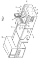
- Fig. 1 is a perspective view showing a nozzle coating equipment according to an embodiment of the present invention;
- Fig. 2 is a perspective view showing the essential portions of the nozzle coating equipment on an enlarged scale;
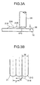
- Figs. 3A and 3B are a sectional side view and a plan view showing the relationship between a nozzle included in the nozzle coating equipment and coating lines, respectively;
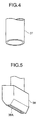
- Fig. 4 is a perspective view showing a modified embodiment of a nozzle included in a nozzle coating equipment;
- Fig. 5 is a perspective view showing another modification of a nozzle included in a nozzle coating equipment;
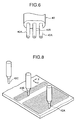
- Fig. 6 is a perspective view showing still another modification of a nozzle included in a nozzle coating equipment;
- Figs. 7A and 7B are bottom plan views each showing yet another modification of a nozzle included in a nozzle coating equipment;
- Fig. 8 is a perspective view showing a different example of arrangement of nozzles included in a nozzle coating equipment;
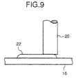
- Fig. 9 is a sectional side view showing a coating operation state where the gap between a nozzle and a glass plate is set less than the film thickness of a coated surface.
-
- Now, a nozzle coating equipment according to an embodiment of the present invention will be described in detail with reference to the drawings.
- The
nozzle coating equipment 10 in the embodiment of the present invention comprises acoating section 11, acarriage 24 and adrying section 26. Thecoating section 11 is so constructed and operated that, while a coating solution contained in aliquid vessel 18 called "dispenser" is being discharged from anozzle 20 provided at the lower end of theliquid vessel 18, onto aglass plate 16 for a plasma display panel (abbreviated to "PDP") put on thehorizontal support plate 14 of an X -Y robot 12, theliquid vessel 18 is driven in X- and Y-direction s along the upper surface of theglass plate 16 by the X -Y robot 12. Thus, the upper surface of theglass plate 16 is coated with the coating solution so as to form a coatedsurface 22. - As seen from Fig. 1, the
glass plate 16 formed with the coatedsurface 22 is transported via thecarriage 24 to thedrying section 26, in which it is dried to complete the coating. - The
liquid vessel 18 is connected with acoating solution tank 28 through aflexible pipe 18A, and is supplied with the coating solution via acontroller 30 from thecoating solution tank 28. - The X -
Y robot 12 is constructed including thesupport plate 14 which is free to reciprocate in the Y-direction on anunderframe 32, and an X-directiona 1driver 12A which is attached to a gate-shaped frame 13 arranged on theunderframe 32 so as to stride over thesupport plate 14, and which is free to reciprocate in the X-direction while supporting theliquid vessel 18. - The
controller 30, which serves for the movement of thesupport plate 14 in the Y-direction, the movement of theX-directional driver 12A in the X-direction and the-supply of the coating solution, is controlled by acontrol device 34 which is-disposed inside theunderframe 32. - As shown in Fig. 2 and Figs. 3A and 3B, the lower-end discharge port of the
nozzle 20 is arranged in proximity to the upper surface of theglass plate 16, and thegap 36 between the discharge port and the upper surface is set so as to agree with the desired coating film thickness of the coatedsurface 22 which is formed by the coating with the coating solution. - In addition, the
control device 34 controls the Y-directional feed of thesupport plate 14 and the X-directional feed of theX-directional driver 12A as stated below. - As shown in Fig. 2 and Fig. 3B by way of example, while the liquid vessel 18 (the nozzle 20) is being reciprocated in a straight line in the X-direction by the
X-directional driver 12A, thesupport plate 14 is driven a predetermined pitch P in the Y-direct ion on one way of the reciprocation. - Here, the pitch P is set smaller than the width W of each coating line of the coating solution formed by the
nozzle 20. Thus, onecoating line 21 by thenozzle 20 is formed in a manner to overlap another coating line adjoining it in the Y-direction, in the widthwise direction of the coating lines. - Moreover, the widthwise pitch P of the coating lines 21 is determined depending upon the diameter of the discharge port of the
nozzle 20, the discharge pressure of the coating solution at the discharge port, and the properties of the coating solution including a viscosity and a surface tension. - By way of example, conditions may be set as explained below. The coating solution is endowed with a viscosity of 40,000 centipoises by adjusting the quantity of addition of a solvent in a paste which is mainly composed of inorganic powder and a vehicle. The
gap 36 between the lower end of thenozzle 20 and the upper surface of theglass plate 16 has a value of 230 µm which is equal to the desired film thickness of the coating film (230 µm before the drying). The tip of thenozzle 20 is in a circular shape which has an inside diameter of 2 mm and an outside diameter of 3 mm . Theglass plate 16 is of 8-inch size. The moving rate of thenozzle 20 is 60 mm/second in the X-direction. The Y-directional pitch is P = 1.6 mm . - Accordingly, when the width of each coating line is set at W = 2 mm (with the coating pitch P = 1.6 mm ), the magnitude of the widthwise overlap between the adjacent coating lines becomes 0.4 mm.
- Further, the
control device 34 is so contrived that, when thesupport plate 14 is driven one pitch P in the Y-direction after onecoating line 21 has been formed owing to the X-directional drive of thenozzle 20, thecontroller 30 cuts off the exertion of a pressure on theliquid vessel 18 so as to suspend the discharge of the coating solution from thenozzle 20. - Next, there will be described a process in which the coating solution is applied onto the
glass plate 16 by thenozzle coating equipment 10. - First, the
support plate 14 is driven to the position of the origin in the Y-direction, and theglass plate 16 is set on thesupport plate 14. Subsequently, while being supplied with the coating solution under pressure from thecoating solution tank 28 through thecontroller 30, the liquid vessel 18 (the nozzle 20) is rectilinearly moved in the X-direction by theX-directional driver 12A. Thus, thefirst coating line 21A is formed. Incidentally, the pressure which is exerted on theliquid vessel 18 is 1 thru 3 kgf/cm2, and it is held constant during the formation of the coating line. The moving rate of thenozzle 20 in the X-direction, the width W of the coating line and the pitch P in the Y-direction are set as mentioned above. - When the formation of the
first coating line 21A has ended, the discharge of the coating solution from thenozzle 20 is suspended. Therefore, the film thickness of thecoated surface 22 is prevented from becoming greater at the terminating end of thecoating line 21A than at any other part. - Subsequently, the
support plate 14 is driven one pitch of 1.6 mm in the Y-direction. Thereafter, thenozzle 20 is driven in the sense opposite to that of thefirst coating line 21A by theX-directio nal driver 12A. Thenozzle 20 thus driven to the initiating end of thesecond coating line 21B is moved in the X-direction similarly to the above, whereby thesecond coating line 21B is formed. - Owing to the iteration of the above operations, the
coated surface 22 having an area of 200 mm × 130 mm is deposited on theglass plate 16 of the 8-inch size by way of example. - The drying of the
coated surface 22 in thedrying section 26 proceeds as follows by way of example. First, thecoated surface 22 is preliminarily dried at 120 °C for 20 thru 30 'minutes . Subsequently, it is finally dried at 170 °C for 10 thru 20 minutes . - In the case where the preliminary drying at the temperature lower than that of the final drying precedes the final drying in this manner, dents 22A having appeared at the widthwise overlap parts between the respectively adjacent ones of the first -
third coating lines 21A - 21C are smoothed out as shown in Fig. 3A by way of example. The smoothed state is fixed by the final drying which is performed after the preliminary drying. - If the final drying is performed from the beginning without the preliminary drying, there will arise the problem that the
coated surface 22 subjected to the final drying is not leveled due to the fixation of thedents 22A or the appearance of cracks in thecoated surface 22. - In an example, the
glass plate 16 was coated with the coating solution and was dried under the conditions mentioned above. The surface roughness of thecoated surface 22 in the example was measured by a surface roughness tester ("Tally-Surf"). Then, the flatness of thecoated surface 22 was within 5 µm relative to the film thickness, 140 µm of the driedcoated surface 22. - The
nozzle 20 in thenozzle coating equipment 10 described above has the discharge port whose cross-section is circular, but the present invention is not restricted to the exemplifiednozzle 20. By way of example, thenozzle 20 may well be replaced with anelliptical nozzle 37 of elliptical cross-section as shown in Fig. 4, or with a slit-shapednozzle 38 having a slit-like discharge port 38A as shown in Fig. 5. Alternatively, it is allowed to employ amulti-nozzle structure 40 including a plurality ofcomponent nozzles 40A as shown in Fig. 6, Fig. 7A or Fig. 7B. - Each of the
elliptical nozzle 37 and the slit-shapednozzle 38 widens thecoating line 21, and therefore enhances the rate of the coating operation. - In the case of the
multi-nozzle structure 40, thecomponent nozzles 40A can be especially arranged as shown in Fig. 7A or Fig. 7B in order that, when the coating solution is discharged from therespective component nozzles 40A, a plurality of coating lines may be formed having a desired magnitude of overlap (for example, 0.4 mm ). Thus, themulti-nozzle structure 40 can achieve the same effect as that of theelliptical nozzle 36 or the slit-shapednozzle 38. - Further, the single nozzle or the single multi-nozzle structure in the nozzle coating equipment is not restrictive. As shown in Fig. 8, a plurality of nozzles may well.be disposed in the Y-direction at regular intervals each of which is integral times the pitch P of the coating lines.
- In this case, the Y-directional interval between the
nth nozzle 42A precedent in the Y-direction and the succedent (n + 1)th nozzle 42B, and the interval between the (n + 2)th nozzle 42C and the (n + 1)th nozzle 42B are integral times the Y-directional pitch P and are equal as explained above. Besides, all thenozzles 42A - 42C are driven synchronously or asynchronously in both the X-direction and the Y-direction. Herein, the drive is controlled by thecontrol device 34 so that the coating line formed first by thenth nozzle 42A and the coating line formed last by the (n + 1)th nozzle 42B may overlap each other in the widthwise direction of the coating lines, similarly to the coating lines shown in Fig. 2 and Figs. 3A and 3B. - Also in the case of employing the plurality of
nozzles 42A - 42C, parts of the operation of coating the surface to-be-coated with the coating solution are respectively allotted to these nozzles, and hence, the rate of the coating operation can be enhanced. - Incidentally, the X -
Y robot 12 included in thenozzle coating equipment 10 described before drives thesupport plate 14 in the Y-direction and drives theliquid vessel 18 in the X-direction through theX-directional driver 12A, whereby the predetermined region of theglass plate 16 is coated with the coating solution by thenozzle 20. The present invention, however, is not restricted to the exemplifiedrobot 12. It is also allowed to fix the side of thesupport plate 14 and to drive theliquid vessel 18 in the X- and Y-directions, or to fix theliquid vessel 18 and to drive the side of thesupport plate 14 in the X- and Y-directions. Further, both theliquid vessel 18 and thesupport plate 14 may well be driven in the X- and Y-directio ns so as to coat theglass plate 16 with the coating solution. - Besides, in the
nozzle coating equipment 10 described before, thegap 36 between the tip of thenozzle 20 and the surface to-be-coated of theglass plate 16 is set equal to the desired film (not dried) thickness of thecoated surface 22. - As illustrated in Fig. 9, the spacing between the
nozzle 20 and theglass plate 16 may well be set less than the desired film thickness of thecoated surface 22 so as to coat theglass plate 16 with the coating solution. - In this case, the surface of the layer of the coating solution discharged onto the
glass plate 16 from the tip of thenozzle 20 is stirred in the X-direction. Therefore, thedents 22A between the respectivelyadjacent coating lines 21 as shown in Fig. 2 and Figs. 3A and 3B are moderated. Accordingly, the surface ruggedness of thecoated surface 22 becomes smaller. - Further, in the
nozzle coating equipment 10 described before, the whole surface of theglass plate 16 for the plasma display panel is formed by so-called "allover coating" with a barrier rib forming layer on the basis of which the barrier rib of the PDP is formed. However, this aspect of the coating operation is not restrictive, but only the predetermined region of theglass plate 16 can be coated with the coating solution by controlling thenozzle 20 and thesupport plate 14 in the X- and Y-directions by means of thecontrol device 34. That is, the patterning of the coated surface is possible. - With such a measure, the unnecessary parts of the barrier rib forming layer after the baking thereof may be removed in a smaller area. Moreover, the coating lines can be directly used as the barrier rib in some cases by making the diameter of the hole of the
nozzle 20 smaller and enhancing the precisions of the movements in the X- and Y-directions. Besides, in the foregoing embodiment, thenozzle 20 is moved along the rectilinear coating lines. However, the present invention is not restricted to the exemplified operation, but it shall also cover a case where a workpiece to-be-coated is coated with the coating solution along coating lines in the shape of a curve such as a circular arc or a spiral by controlling thenozzle 20 and thesupport plate 14 in the X- and Y-directions by means of thecontrol device 34. - Further, the present invention is not utilized only for the formation of the .barrier rib of the plasma display panel, but it can be utilized also for the formation of thick film patterns in processes for manufacturing a liquid-crystal display device, a phosphorescent display device, a hybrid integrated circuit, etc.
Claims (14)
- A nozzle coating method comprising the step of coating a planar surface to-be-coated of a workpiece (16) with a coating solution in parallel coating lines (21A, 21B, 21C...) in such a way that a nozzle (20) is moved relatively to and in parallel with the surface to-be-coated while the coating solution is being discharged from a tip of the nozzle (20) in a state in which the nozzle tip is spaced from the surface to-be-coated, and the step of iteratively coating the surface to-be-coated in succession in such a manner that a next coating line in a widthwise direction thereof overlaps the previous coating line in the widthwise direction, thereby to form a coated surface (22), characterized in that a gap (36) between the surface to-be-coated and the nozzle (20) tip is set substantially equal to or smaller than a desired film thickness of the coated surface (22).
- A nozzle coating method according to claim 1, wherein the discharge of the coating solution from the nozzle (20) tip is suspended while the nozzle is shifted from a terminating end of a certain one of the coating lines (21A ~ 21C, ...) to an initiating end of a next one of the coating lines.
- A nozzle coating method according to claim 1 or 2, wherein a widthwise pitch (P) of the coating lines (21A, 21B, 21C, ...) is set depending upon a diameter of a discharge port of the nozzle (20), a discharge pressure of the coating solution at the discharge port, and properties of the coating solution including a viscosity and a surface tension.
- A nozzle coating method according to any of claims 1 to 3, wherein the nozzle (42A) and at least one other nozzle (42B, 42C) are so arranged that the plurality of nozzles are spaced at a predetermined interval which is integral times a widthwise pitch (P) of the coating lines (21A. 21B, 21C, ...), in the widthwise direction of the coating lines (21A, 21B, 21C, ...), and the surface to-be-coated is coated by moving the individual nozzles (42A, 42B, 42C) relatively thereto in such a manner that a first one of the coating lines based on a certain one of the individual nozzles (42A, 42B, 42C) and a last one of the coating lines based on another of the individual nozzles adjoining the certain nozzle rearward of the certain nozzle in the widthwise pitch (P) feed direction thereof overlap each other in the widthwise direction.
- A nozzle coating method according to any of claims 1 to 4, wherein the coating solution contains a solvent, and the coated surface (22) is let stand in a temperature environment for a predetermined time period after the formation of the coated surface (22) and before final drying for vaporizing the contained solvent which remains in the coated surface (22), the temperature environment having a temperature lower than that of the final drying and being capable of lowering a viscosity of the coating solution of the coated surface, thereby to uniformalize a film thickness of the coated surface (22).
- A nozzle coating method according to any of claims 1 to 5, wherein the workpiece to-be-coated is a glass plate (16) of a plasma display panel, and at least a part of the coated surface (22) is a barrier rib which is to be formed on the glass plate (16) for the purpose of isolating discharge cells of the plasma display panel from one another.
- A nozzle coating method according to claim 6, wherein a film thickness of the coated surface (22) is set at 150 µm through 200 µm inclusive in terms of a value after drying.
- A nozzle coating equipment comprising a workpiece bed (14) which supports a workpiece (16) with a planar surface to-be-coated of the workpiece (16) looking upward, a liquid vessel(18) which is filled with a coating solution and which is fumished with a nozzle (20) at its lower end so as to discharge the coating solution from the nozzle (20) under action of a pressure, and a drive system (12) which supports the liquid vessel (18) with the nozzle (20) lying in downward proximity to the surface to-be-coated of the workpiece (16) fixed to the workpiece bed (14) and which drives at least either of the liquid vessel (18) and the workpiece bed (14) so as to move the nozzle (20) relatively to the surface to-be-coated in parallel coating lines; the drive system (12) including a control device (34) which controls the relative movement in such a manner that a coating line (21A) of the coating solution to be discharged from the nozzle onto the surface to-be-coated and a coating line adjacent (21B) to the first-mentioned coating line (21A) overlap each other in a widthwise direction of the coating lines (21A, 21B), characterized in that the drive system (12) supports the workpiece (16) and the liquid vessel (18) in such a manner that, during the relative movement between the workpiece (16) and the liquid vessel (18), a gap (36) which is formed between the surface to-be-coated and a tip of the nozzle (20) becomes substantially equal to or smaller than a desired film thickness of a layer coated by the nozzle (20).
- A nozzle coating equipment according to claim 8, wherein a cross-sectional shape of a tip of the nozzle (37, 38) in the liquid vessel (18) is any of a circle, an ellipse and a slit (38A) shape.
- A nozzle coating equipment according to one of claims 1-9, wherein the liquid vessel (18) is furnished with at least one other nozzle (40A, 42B, 42C) of the same type as that of the first-mentioned nozzle, and the plurality of nozzles (40A, 42A~42C) are so arranged as to be spaced from each other in the widthwise direction of the coating lines (21A, 21B, 21C,...).
- A nozzle coating equipment according to claim 10, wherein the nozzle (42A) and at least one other nozzle (42B, 42C) are so arranged that the plurality of nozzles (42A ~ 42C) are spaced at a predetermined interval which is integral times a widthwise pitch (P) of the coating lines (21A, 21B, 21C).
- A nozzle coating equipment according to claim 10 or 11, wherein the drive system (12) is constructed so as to drive the plurality of nozzles (42A ~ 42C) synchronously.
- A nozzle coating equipment according to one of claims 8 to 12, wherein the drive system includes an X - Y robot (12) which supports the liquid vessel (18) and moves the liquid vessel (18) relatively to the workpiece (16).
- A nozzle coating equipment as defined in any of claims 8 to 13, wherein the drive system includes an X - Y stage (14) which moves a glass plate (16) being the workpiece in X- and Y-directions along the surface to-be-coated, relatively to the liquid vessel (18).
Applications Claiming Priority (3)
| Application Number | Priority Date | Filing Date | Title |
|---|---|---|---|
| JP244436/95 | 1995-09-22 | ||
| JP7244436A JPH0992134A (en) | 1995-09-22 | 1995-09-22 | Nozzle coating method and device |
| JP24443695 | 1995-09-22 |
Publications (2)
| Publication Number | Publication Date |
|---|---|
| EP0765694A1 EP0765694A1 (en) | 1997-04-02 |
| EP0765694B1 true EP0765694B1 (en) | 2002-08-28 |
Family
ID=17118630
Family Applications (1)
| Application Number | Title | Priority Date | Filing Date |
|---|---|---|---|
| EP96115179A Expired - Lifetime EP0765694B1 (en) | 1995-09-22 | 1996-09-20 | Nozzle coating method and equipment |
Country Status (4)
| Country | Link |
|---|---|
| US (1) | US5776545A (en) |
| EP (1) | EP0765694B1 (en) |
| JP (1) | JPH0992134A (en) |
| DE (1) | DE69623213T2 (en) |
Families Citing this family (42)
| Publication number | Priority date | Publication date | Assignee | Title |
|---|---|---|---|---|
| ID21831A (en) * | 1996-12-17 | 1999-07-29 | Toray Industries | METHODS AND EQUIPMENT FOR PRODUCING PLASMA DISPLAY |
| EP0950438A1 (en) * | 1998-03-19 | 1999-10-20 | Schablonentechnik Kufstein Aktiengesellschaft | Process for making a pattern on the surface of a substrate |
| GB9808806D0 (en) * | 1998-04-24 | 1998-06-24 | Cambridge Display Tech Ltd | Selective deposition of polymer films |
| US6231917B1 (en) | 1998-06-19 | 2001-05-15 | Kabushiki Kaisha Toshiba | Method of forming liquid film |
| US6352763B1 (en) | 1998-12-23 | 2002-03-05 | 3M Innovative Properties Company | Curable slurry for forming ceramic microstructures on a substrate using a mold |
| US6247986B1 (en) | 1998-12-23 | 2001-06-19 | 3M Innovative Properties Company | Method for precise molding and alignment of structures on a substrate using a stretchable mold |
| US7125584B2 (en) * | 1999-09-27 | 2006-10-24 | Kabushiki Kaisha Toshiba | Method for forming a liquid film on a substrate |
| JP3697389B2 (en) | 1999-09-27 | 2005-09-21 | 株式会社東芝 | Liquid film forming method and coating film forming method |
| US6695922B2 (en) * | 1999-12-15 | 2004-02-24 | Tokyo Electron Limited | Film forming unit |
| US6821178B2 (en) | 2000-06-08 | 2004-11-23 | 3M Innovative Properties Company | Method of producing barrier ribs for plasma display panel substrates |
| JP3366630B2 (en) * | 2000-10-04 | 2003-01-14 | 大日本スクリーン製造株式会社 | Method and apparatus for forming barrier ribs for flat display device |
| JP3425946B2 (en) * | 2001-09-13 | 2003-07-14 | 大日本スクリーン製造株式会社 | Method and apparatus for forming barrier ribs for flat display device |
| US7033534B2 (en) * | 2001-10-09 | 2006-04-25 | 3M Innovative Properties Company | Method for forming microstructures on a substrate using a mold |
| US7176492B2 (en) * | 2001-10-09 | 2007-02-13 | 3M Innovative Properties Company | Method for forming ceramic microstructures on a substrate using a mold and articles formed by the method |
| JP2003187694A (en) | 2001-12-21 | 2003-07-04 | Dainippon Screen Mfg Co Ltd | Separation wall forming method, separation wall forming device, and panel |
| JP2003187697A (en) * | 2001-12-21 | 2003-07-04 | Dainippon Screen Mfg Co Ltd | Forming method and forming device of separation wall for flat display device, and back plate formed by the same |
| JP2003272523A (en) * | 2002-01-09 | 2003-09-26 | Dainippon Screen Mfg Co Ltd | Method and device for coating between barrier ribs, method and device for pattern forming, and panel |
| JP2003211045A (en) * | 2002-01-24 | 2003-07-29 | Three Bond Co Ltd | Material coating device |
| MY133543A (en) | 2002-01-24 | 2007-11-30 | Three Bond Co Ltd | Material application apparatus |
| KR100566840B1 (en) | 2002-01-30 | 2006-04-03 | 가부시끼가이샤 도시바 | Deposition Method and Deposition Device |
| KR100532083B1 (en) * | 2002-02-20 | 2005-11-30 | 엘지.필립스 엘시디 주식회사 | A liquid crystal dispensing apparatus having an integrated needle sheet |
| JP3957640B2 (en) * | 2002-02-21 | 2007-08-15 | アイシン化工株式会社 | Wide slit nozzle and coating method with wide slit nozzle |
| US20040217202A1 (en) * | 2003-04-08 | 2004-11-04 | Hynes Anthony J. | Airless conformal coating apparatus and method |
| JP2004330136A (en) * | 2003-05-09 | 2004-11-25 | Seiko Epson Corp | Liquid film drying method, organic EL panel manufacturing method, electro-optical panel manufacturing method and electronic device manufacturing method, and liquid film drying device, electro-optical panel, electro-optical device and electronic device |
| KR100987897B1 (en) * | 2003-11-25 | 2010-10-13 | 엘지디스플레이 주식회사 | Dispenser of liquid crystal display panel and dispensing method using the same |
| KR101025103B1 (en) * | 2004-03-30 | 2011-03-25 | 엘지디스플레이 주식회사 | Photoresist coating apparatus having slit nozzle |
| JP2006066148A (en) * | 2004-08-25 | 2006-03-09 | Dainippon Screen Mfg Co Ltd | Panel for planar display device |
| KR100627361B1 (en) * | 2004-09-20 | 2006-09-21 | 삼성에스디아이 주식회사 | Plasma Display Panel And Method Of Manufacturing The Same |
| JP4617875B2 (en) * | 2004-12-27 | 2011-01-26 | セイコーエプソン株式会社 | Manufacturing method of liquid crystal device |
| JP4980644B2 (en) * | 2005-05-30 | 2012-07-18 | 東京エレクトロン株式会社 | Coating method and coating apparatus |
| CN100576077C (en) * | 2005-05-30 | 2009-12-30 | 东京毅力科创株式会社 | Coating method and coating apparatus |
| US11136667B2 (en) * | 2007-01-08 | 2021-10-05 | Eastman Kodak Company | Deposition system and method using a delivery head separated from a substrate by gas pressure |
| CN101939114A (en) | 2008-02-08 | 2011-01-05 | 中央硝子株式会社 | Apparatus and method for coating liquid |
| JP5317675B2 (en) * | 2008-12-22 | 2013-10-16 | 株式会社東芝 | Radiation detector and manufacturing method thereof |
| CN103035455A (en) * | 2010-01-14 | 2013-04-10 | 宜昌劲森照明电子有限公司 | Cold cathode fluorescent lamp electrode inner coating method |
| DE102010044349A1 (en) * | 2010-09-03 | 2012-04-19 | Fraunhofer-Gesellschaft zur Förderung der angewandten Forschung e.V. | Method and device for producing a metallic contact structure for the electrical contacting of a photovoltaic solar cell |
| JP6669498B2 (en) * | 2013-10-25 | 2020-03-18 | 日本板硝子株式会社 | Glass plate manufacturing method and glass plate |
| CN103771719B (en) * | 2014-01-16 | 2015-09-09 | 北京京东方光电科技有限公司 | A kind of apparatus for coating |
| US10000049B2 (en) * | 2014-06-23 | 2018-06-19 | Exel Industries | Methods and apparatus for applying protective films |
| KR102568450B1 (en) * | 2015-08-26 | 2023-08-21 | 쓰리엠 이노베이티브 프로퍼티즈 캄파니 | Methods and apparatus for forming articles having non-uniform discontinuous patterned coatings |
| EP3341136A4 (en) * | 2015-08-26 | 2019-07-24 | 3M Innovative Properties Company | METHOD AND APPARATUS FOR FORMING ARTICLES HAVING NON-UNIFORMLY PATTERNED COATINGS |
| CN110620178A (en) * | 2018-06-19 | 2019-12-27 | 湖北万度光能有限责任公司 | Preparation method of perovskite solar cell |
Family Cites Families (13)
| Publication number | Priority date | Publication date | Assignee | Title |
|---|---|---|---|---|
| DE1761858A1 (en) * | 1968-07-15 | 1971-10-28 | Feldmuehle Ag | Device for coating or impregnating flat webs |
| JPS515324A (en) * | 1974-07-02 | 1976-01-17 | Nippon Sheet Glass Co Ltd | Garasuhyomenheno kinzokusankabutsuhimakukeiseisochi |
| US4038442A (en) * | 1975-09-16 | 1977-07-26 | Fuji Photo Film Co., Ltd. | Method for coating |
| DE2704126C2 (en) * | 1977-01-28 | 1979-04-12 | Mannesmann Ag, 4000 Duesseldorf | Method and device for producing a corrosion protection layer on pipes or other elongated steel profiles |
| KR910003690B1 (en) * | 1988-09-14 | 1991-06-08 | Samsung Electronic Devices | Pdp manufacturing method |
| KR910003693B1 (en) * | 1988-09-14 | 1991-06-08 | Samsung Electronic Devices | Pdp barrack manufacturing method |
| EP0424551A1 (en) * | 1989-10-23 | 1991-05-02 | Karl Reinhard Zeiss | Method for the production and processing of multi-component reactive polymer mixtures |
| GB2245508B (en) * | 1990-06-28 | 1995-02-01 | Nec Corp | Spray type flux applying device |
| KR930011088A (en) * | 1991-11-26 | 1993-06-23 | 이헌조 | Method of forming conductive film of cathode ray tube |
| US5348585A (en) * | 1993-01-07 | 1994-09-20 | Weston Colin K | Liquid dispensing apparatus |
| CH686187A5 (en) * | 1993-03-30 | 1996-01-31 | Alusuisse Lonza Services Ag | Metal substrates with laser-induced MMC coating. |
| DE4325653C2 (en) * | 1993-07-30 | 1995-07-20 | Bayer Ag | Method and device for coating a body rotating about an axis |
| GB2280391A (en) * | 1993-07-31 | 1995-02-01 | Valpar Ind Ltd | Coating pipes, cables or hoses |
-
1995
- 1995-09-22 JP JP7244436A patent/JPH0992134A/en active Pending
-
1996
- 1996-09-20 US US08/717,348 patent/US5776545A/en not_active Expired - Fee Related
- 1996-09-20 EP EP96115179A patent/EP0765694B1/en not_active Expired - Lifetime
- 1996-09-20 DE DE69623213T patent/DE69623213T2/en not_active Expired - Fee Related
Also Published As
| Publication number | Publication date |
|---|---|
| JPH0992134A (en) | 1997-04-04 |
| DE69623213D1 (en) | 2002-10-02 |
| DE69623213T2 (en) | 2002-12-19 |
| EP0765694A1 (en) | 1997-04-02 |
| US5776545A (en) | 1998-07-07 |
Similar Documents
| Publication | Publication Date | Title |
|---|---|---|
| US5776545A (en) | Nozzle coating method and equipment | |
| US5921836A (en) | Apparatus for forming fluorescent layers of a plasma display panel and method therefor | |
| KR19990007960A (en) | Liquid coating nozzle, liquid coating nozzle manufacturing method, liquid coating method, liquid coating apparatus and cathode ray tube manufacturing method | |
| CN100532099C (en) | Self-contained vacuum module for stencil wiper assembly | |
| KR100578617B1 (en) | Liquid crystal dropping apparatus and method and liquid crystal display panel manufacturing apparatus | |
| JP4059305B2 (en) | Screen printing device | |
| KR100683688B1 (en) | Dielectric layer forming apparatus and manufacturing method of plasma display panel using same | |
| JPH11239750A (en) | Apparatus and method for applying coating liquid to uneven substrate, and apparatus and method for manufacturing plasma display | |
| US20070070105A1 (en) | Methods and apparatus for adjusting pixel fill profiles | |
| EP0951048A1 (en) | Method for forming phosphor layers of plasma display panel and apparatus therefor | |
| JP4324998B2 (en) | Coating apparatus and coating method, and plasma display manufacturing method and manufacturing apparatus | |
| JP2012192332A (en) | Coating apparatus, coating method, and method for manufacturing display member | |
| JP2001357780A (en) | Plasma display panel manufacturing method and manufacturing apparatus | |
| CN1198247A (en) | Supply of color cells on a substrate by screen printing or stencil printing | |
| JP2000102759A (en) | Coating method and coating apparatus, and method and apparatus for manufacturing plasma display and display member | |
| JP2013208521A (en) | Method for applying coating liquid and method for producing member for display | |
| JP2002140982A (en) | Apparatus and method for manufacturing light emitting substrate for plasma display | |
| JP2004009587A (en) | Thick film paste printing machine and coating method of thick film paste | |
| JP2004141707A (en) | Coating method and coating apparatus, and method for manufacturing member for plasma display | |
| US7037161B2 (en) | Method of manufacturing flat panel displays utilizing a surface treating layer | |
| JP2001000904A (en) | Coating apparatus and method, and plasma display and display member manufacturing apparatus and method | |
| JPH11239748A (en) | Apparatus and method for applying coating liquid to uneven substrate, and apparatus and method for manufacturing plasma display | |
| JP3907491B2 (en) | Pattern forming device | |
| JPH11239749A (en) | Apparatus and method for applying coating liquid to uneven substrate, and apparatus and method for manufacturing plasma display | |
| JPH11262995A (en) | Screen printing method |
Legal Events
| Date | Code | Title | Description |
|---|---|---|---|
| PUAI | Public reference made under article 153(3) epc to a published international application that has entered the european phase |
Free format text: ORIGINAL CODE: 0009012 |
|
| AK | Designated contracting states |
Kind code of ref document: A1 Designated state(s): DE FR GB |
|
| 17P | Request for examination filed |
Effective date: 19970813 |
|
| 17Q | First examination report despatched |
Effective date: 19990426 |
|
| GRAG | Despatch of communication of intention to grant |
Free format text: ORIGINAL CODE: EPIDOS AGRA |
|
| GRAG | Despatch of communication of intention to grant |
Free format text: ORIGINAL CODE: EPIDOS AGRA |
|
| GRAH | Despatch of communication of intention to grant a patent |
Free format text: ORIGINAL CODE: EPIDOS IGRA |
|
| GRAH | Despatch of communication of intention to grant a patent |
Free format text: ORIGINAL CODE: EPIDOS IGRA |
|
| GRAA | (expected) grant |
Free format text: ORIGINAL CODE: 0009210 |
|
| AK | Designated contracting states |
Kind code of ref document: B1 Designated state(s): DE FR GB |
|
| REG | Reference to a national code |
Ref country code: GB Ref legal event code: FG4D |
|
| RIN1 | Information on inventor provided before grant (corrected) |
Inventor name: SHIOZAKI, KAZUYUKI, C/O DAI NIPPON PRINTING CO,LT Inventor name: WATANABE, KAZUO, C/O DAI NIPPON PRINTING CO., LTD Inventor name: OHASHI, YOICHIRO, C/O DAI NIPPON PRINTING CO., LT Inventor name: YOSHIBA, HIROSHI, C/O DAI NIPPON PRINTING CO., LTD |
|
| REF | Corresponds to: |
Ref document number: 69623213 Country of ref document: DE Date of ref document: 20021002 |
|
| ET | Fr: translation filed | ||
| PLBE | No opposition filed within time limit |
Free format text: ORIGINAL CODE: 0009261 |
|
| STAA | Information on the status of an ep patent application or granted ep patent |
Free format text: STATUS: NO OPPOSITION FILED WITHIN TIME LIMIT |
|
| 26N | No opposition filed |
Effective date: 20030530 |
|
| PGFP | Annual fee paid to national office [announced via postgrant information from national office to epo] |
Ref country code: DE Payment date: 20070907 Year of fee payment: 12 |
|
| PGFP | Annual fee paid to national office [announced via postgrant information from national office to epo] |
Ref country code: GB Payment date: 20070823 Year of fee payment: 12 |
|
| PGFP | Annual fee paid to national office [announced via postgrant information from national office to epo] |
Ref country code: FR Payment date: 20070821 Year of fee payment: 12 |
|
| GBPC | Gb: european patent ceased through non-payment of renewal fee |
Effective date: 20080920 |
|
| REG | Reference to a national code |
Ref country code: FR Ref legal event code: ST Effective date: 20090529 |
|
| PG25 | Lapsed in a contracting state [announced via postgrant information from national office to epo] |
Ref country code: DE Free format text: LAPSE BECAUSE OF NON-PAYMENT OF DUE FEES Effective date: 20090401 |
|
| PG25 | Lapsed in a contracting state [announced via postgrant information from national office to epo] |
Ref country code: FR Free format text: LAPSE BECAUSE OF NON-PAYMENT OF DUE FEES Effective date: 20080930 |
|
| PG25 | Lapsed in a contracting state [announced via postgrant information from national office to epo] |
Ref country code: GB Free format text: LAPSE BECAUSE OF NON-PAYMENT OF DUE FEES Effective date: 20080920 |