EP0765652B1 - Wiederverschliessbare Behälteranordnung mit Membrane und Schieber - Google Patents
Wiederverschliessbare Behälteranordnung mit Membrane und Schieber Download PDFInfo
- Publication number
- EP0765652B1 EP0765652B1 EP96114815A EP96114815A EP0765652B1 EP 0765652 B1 EP0765652 B1 EP 0765652B1 EP 96114815 A EP96114815 A EP 96114815A EP 96114815 A EP96114815 A EP 96114815A EP 0765652 B1 EP0765652 B1 EP 0765652B1
- Authority
- EP
- European Patent Office
- Prior art keywords
- pusher
- recess
- membrane
- fluid
- disposed
- Prior art date
- Legal status (The legal status is an assumption and is not a legal conclusion. Google has not performed a legal analysis and makes no representation as to the accuracy of the status listed.)
- Expired - Lifetime
Links
- 239000012528 membrane Substances 0.000 title claims description 95
- 239000012530 fluid Substances 0.000 claims description 94
- 238000007789 sealing Methods 0.000 claims description 42
- 230000037361 pathway Effects 0.000 claims description 27
- 238000004891 communication Methods 0.000 claims description 11
- 239000003814 drug Substances 0.000 description 35
- 229940079593 drug Drugs 0.000 description 31
- 230000036512 infertility Effects 0.000 description 5
- 230000009471 action Effects 0.000 description 4
- 239000000463 material Substances 0.000 description 4
- 239000002904 solvent Substances 0.000 description 4
- 239000011324 bead Substances 0.000 description 3
- 238000006073 displacement reaction Methods 0.000 description 3
- 229920001971 elastomer Polymers 0.000 description 3
- 239000007788 liquid Substances 0.000 description 3
- 230000014759 maintenance of location Effects 0.000 description 3
- 239000000243 solution Substances 0.000 description 3
- 239000000853 adhesive Substances 0.000 description 2
- 230000001070 adhesive effect Effects 0.000 description 2
- 230000000295 complement effect Effects 0.000 description 2
- 230000000694 effects Effects 0.000 description 2
- 239000013536 elastomeric material Substances 0.000 description 2
- 230000002708 enhancing effect Effects 0.000 description 2
- 239000011521 glass Substances 0.000 description 2
- 238000003780 insertion Methods 0.000 description 2
- 230000037431 insertion Effects 0.000 description 2
- 238000000034 method Methods 0.000 description 2
- 230000004048 modification Effects 0.000 description 2
- 238000012986 modification Methods 0.000 description 2
- 229920003052 natural elastomer Polymers 0.000 description 2
- 229920001194 natural rubber Polymers 0.000 description 2
- 239000004033 plastic Substances 0.000 description 2
- 229920003023 plastic Polymers 0.000 description 2
- 230000000717 retained effect Effects 0.000 description 2
- 239000005060 rubber Substances 0.000 description 2
- 239000003566 sealing material Substances 0.000 description 2
- 229920003051 synthetic elastomer Polymers 0.000 description 2
- 239000005061 synthetic rubber Substances 0.000 description 2
- 238000003466 welding Methods 0.000 description 2
- FAPWRFPIFSIZLT-UHFFFAOYSA-M Sodium chloride Chemical compound [Na+].[Cl-] FAPWRFPIFSIZLT-UHFFFAOYSA-M 0.000 description 1
- 230000002411 adverse Effects 0.000 description 1
- 230000000712 assembly Effects 0.000 description 1
- 238000000429 assembly Methods 0.000 description 1
- 230000004888 barrier function Effects 0.000 description 1
- 239000002775 capsule Substances 0.000 description 1
- 239000000356 contaminant Substances 0.000 description 1
- 238000013461 design Methods 0.000 description 1
- 239000000806 elastomer Substances 0.000 description 1
- 239000012634 fragment Substances 0.000 description 1
- 230000006870 function Effects 0.000 description 1
- 238000010348 incorporation Methods 0.000 description 1
- 238000002347 injection Methods 0.000 description 1
- 239000007924 injection Substances 0.000 description 1
- 238000004519 manufacturing process Methods 0.000 description 1
- 238000010297 mechanical methods and process Methods 0.000 description 1
- 230000008447 perception Effects 0.000 description 1
- 230000008569 process Effects 0.000 description 1
- 238000000926 separation method Methods 0.000 description 1
- 239000011780 sodium chloride Substances 0.000 description 1
- 229920002725 thermoplastic elastomer Polymers 0.000 description 1
- 238000012546 transfer Methods 0.000 description 1
Images


Classifications
-
- A—HUMAN NECESSITIES
- A61—MEDICAL OR VETERINARY SCIENCE; HYGIENE
- A61J—CONTAINERS SPECIALLY ADAPTED FOR MEDICAL OR PHARMACEUTICAL PURPOSES; DEVICES OR METHODS SPECIALLY ADAPTED FOR BRINGING PHARMACEUTICAL PRODUCTS INTO PARTICULAR PHYSICAL OR ADMINISTERING FORMS; DEVICES FOR ADMINISTERING FOOD OR MEDICINES ORALLY; BABY COMFORTERS; DEVICES FOR RECEIVING SPITTLE
- A61J1/00—Containers specially adapted for medical or pharmaceutical purposes
- A61J1/14—Details; Accessories therefor
- A61J1/20—Arrangements for transferring or mixing fluids, e.g. from vial to syringe
- A61J1/2096—Combination of a vial and a syringe for transferring or mixing their contents
-
- A—HUMAN NECESSITIES
- A61—MEDICAL OR VETERINARY SCIENCE; HYGIENE
- A61J—CONTAINERS SPECIALLY ADAPTED FOR MEDICAL OR PHARMACEUTICAL PURPOSES; DEVICES OR METHODS SPECIALLY ADAPTED FOR BRINGING PHARMACEUTICAL PRODUCTS INTO PARTICULAR PHYSICAL OR ADMINISTERING FORMS; DEVICES FOR ADMINISTERING FOOD OR MEDICINES ORALLY; BABY COMFORTERS; DEVICES FOR RECEIVING SPITTLE
- A61J1/00—Containers specially adapted for medical or pharmaceutical purposes
- A61J1/14—Details; Accessories therefor
- A61J1/20—Arrangements for transferring or mixing fluids, e.g. from vial to syringe
- A61J1/2003—Accessories used in combination with means for transfer or mixing of fluids, e.g. for activating fluid flow, separating fluids, filtering fluid or venting
- A61J1/202—Separating means
- A61J1/2037—Separating means having valve means
-
- Y—GENERAL TAGGING OF NEW TECHNOLOGICAL DEVELOPMENTS; GENERAL TAGGING OF CROSS-SECTIONAL TECHNOLOGIES SPANNING OVER SEVERAL SECTIONS OF THE IPC; TECHNICAL SUBJECTS COVERED BY FORMER USPC CROSS-REFERENCE ART COLLECTIONS [XRACs] AND DIGESTS
- Y10—TECHNICAL SUBJECTS COVERED BY FORMER USPC
- Y10S—TECHNICAL SUBJECTS COVERED BY FORMER USPC CROSS-REFERENCE ART COLLECTIONS [XRACs] AND DIGESTS
- Y10S215/00—Bottles and jars
- Y10S215/03—Medical
Definitions
- the invention relates to a resealable container assembly, and more particularly, to a resealable container assembly employing a membrane and pusher for efficient transfer of fluid.
- Dry drugs such as powdered or lyophilized drugs are typically stored in sealed bottles or vials.
- the drug is accessed shortly prior to use by rupturing or displacing the seal provided on the vial.
- a solvent solution such as saline is then introduced into the vial to reconstitute the powdered or lyophilized drug. Once reconstituted, the drug solution is extracted from the vial for use.
- Some prior art vials of powdered or lyophilized drugs include a pierceable membrane secured across the open top of the prior art vial.
- the membrane is normally pierced by a needle in communication with the solvent.
- care must be taken to avoid the separation of membrane fragments when the seal is pierced, as these may be accidentally delivered to the patient.
- These seals typically must be pierced each time access to the solvent is desired, heightening the problems associated therewith.
- Stoppers are normally formulated from materials selected for compatibility with the drug stored in the vial. Hence, the stoppers typically pose no harm to the safety of the drug, whether lyophilized or reconstituted. However, the appearance of a stopper within the interior of the vial often leads to the perception ⁇ however flawed-that the drug will be adversely affected by the presence of the stopper. There may also be a perception that the presence of the stopper within the vial impedes good flow of the drug solution.
- US-A-5 425 465 discloses a resealable container assembly comprising a container having an open top, an interior in fluid communication with the open top, and a top surface surrounding said open top.
- the assembly comprises also a body disposed adjacent the top surface of the container, defining a recess having a fluid path with the open top of the container.
- Within the said body there is affixed the periphery of an elastomeric membrane which has a central slit defining a normally closed fluid passage. A central portion of said membrane is displaceable between a sealing position and an open position, to close and open the fluid path, respectively.
- a pusher having an axial passage is disposed in the recess defined by said body and has a top end for contact with the nose portion of a syringe and a bottom end for contact with the membrane. Said bottom end of the pusher is sharply pointed so as to be able to force its way through the central, deformable portion of the membrane.
- An object of the present invention is to provide an improved resealable container assembly.
- the container assembly permits a practitioner repeated access to the drug held in a bottle while at the same time preserving its sterility.
- the bottle includes an interior, an open top in fluid communication with the interior, and a top surface disposed around portions of the bottle surrounding the open top.
- the top surface may be formed, for instance, as an annular rim around the open top.
- the resealable container assembly features a body disposed on the top surface of the bottle.
- the body defines a recess having a fluid path to and from the open top of the bottle.
- a fluid access device such as a luer connector hub is disposed on the body to provide fluid access to and from the recess.
- the luer connector hub includes a connector end configured for access by a component of a medical delivery device, and an opposed end in fluid communication with the recess. If desired, the body and the luer connector hub may be provided as separate components, or they may be integrally formed as one component.
- the resealable container assembly further includes a membrane disposed between the open top of the bottle and the recess defined by the body.
- the membrane which may be formed from an elastomeric material such as various elastomers, natural or synthetic rubbers, or the like, preferably includes a central area having a width at least equal to the width defined by the recess.
- One or more openings or slits are disposed outside the central area to establish in resealable fashion the fluid path between the recess and the open top of the bottle.
- One or more sealing ribs may be disposed on the body about the periphery of the recess. The sealing ribs are preferably disposed for sealing contact with the membrane between the central area and the one or more openings. If desired, the sealing ribs may be provided on the membrane itself.
- the membrane is displaceable between a sealing position, wherein the one or more sealing ribs engage the membrane between the central area and the one or more openings to close the fluid path, and an open position, wherein the one or more ribs are urged away from the membrane, opening the fluid path between the recess and the open top of the bottle.
- the membrane may be supported between the body and the top surface of the bottle and held in place, for instance, by an annular clip retaining the body to the top surface of the bottle.
- the body and top surface of the bottle may be formed as an integral component, with the membrane secured in the integral component so as to be disposed between the recess and the open top of the bottle.
- a pusher is located in the recess defined by the body.
- the pusher preferably includes a top end disposed adjacent the opposed end of the luer connector hub and a bottom end disposed for contact with the membrane.
- the pusher defines one or more fluid pathways between its top and bottom ends so as to facilitate fluid flow through the recess.
- the fluid pathways may be defined by the structure of the pusher; likewise, the pusher may define a width less than the width of the recess, such that a gap exists between the pusher and the recess, establishing the fluid pathway.
- a luer lock seal may be provided which is threadably engageable with the connector end of the luer connector hub.
- the luer lock seal serves to preserve sterility and prevents inadvertent access to the interior of the bottle until use is desired.
- the luer lock seal (if provided) is removed by the practitioner, so that the connector end of the luer connector hub is disposed for access by the medical delivery device.
- the medical delivery device may feature a male luer tip which is insertable through the connector end of the luer connector hub.
- the male luer tip will exert a force against the pusher, such that the pusher will displace the membrane towards the interior of the bottle.
- the one or more ribs will be displaced from their sealing contact with the body, opening the fluid path between the recess and the open top of the bottle, and thereby permitting fluid flow between the medical delivery device and the interior of the bottle via the recess and the fluid path defined between the recess and the open top of the bottle.
- the membrane Upon removing the medical delivery device from contact with the pusher, the membrane will re-deflect towards its closed position, such that the one or more ribs will be re-disposed for sealing contact with the membrane, closing the fluid path.
- the pusher may assume a variety of configurations.
- the pusher may be formed as an elongate plug having a top end disposed through the opposed end of the luer connector hub, and a bottom end disposed for contact with the membrane.
- At least one outwardly protruding notch may be formed between the top and bottom ends of the plug.
- the recess may be formed with a main portion and top and bottom ends that display a width narrower than the width of the main portion.
- the width defined by the notch is greater than the width of the top and bottom ends of the recess.
- the notch serves to prevent inadvertent withdrawal of the plug from the recess.
- the notch may cooperate with either the top or bottom ends of the recess as a second way to seal the device.
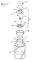
- Figure 1 is an exploded perspective view of either resealable bottle assembly 20 (or 120) mounted to a bottle or vial 10 containing therein a drug 16.
- Drug 16 may entail, for instance, a medicament in powdered or granular form, such as a lyophilized medicament, intended to be reconstituted by a fluid introduced into vial 10 by a medical delivery device such as syringe 60. Alternately, it will be appreciated by the skilled artisan that drug 16 may entail a liquid medicament to which repeated access by the practitioner is desired.
- Syringe 60 may feature, for instance, a male luer tip 62 for introducing fluid into the interior of bottle 10 via a luer connector hub 32 associated with the resealable bottle assembly 20 (or 120), as will be more fully described herein.
- Syringe 60 may also display a luer lock collar 64 surrounding luer tip 62. Internal portions of luer lock collar 64 may include a helicoidal thread 65 threadedly engageable with an edge 35 associated with luer connector hub 32. While syringe 60 is herein depicted as a luer lock syringe, it will be evident to the skilled artisan that the invention is equally amenable to luer slip syringes. It will also be evident to the skilled artisan that syringe 60 may serve to aspirate reconstituted drug 16 from bottle 10.
- bottle 10 may include a neck portion 13 defining an open top 12 with a width "X".
- Bottle 10 further includes a top surface 14 disposed around open top 12.
- top surface 14 is defined by an uppermost portion of an annular rim 15 formed around open top 12 of the bottle. It will be realized by the skilled artisan that the top surface of the bottle may also be established by rings or other means attached about open top 12 of the bottle.
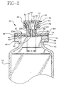
- FIGs 2-7 depict one embodiment 20 of the resealable bottle assembly in accordance with the present invention.
- Resealable bottle assembly 20 features a body 22 having a relatively flat portion 22a and an upwardly extending portion 22b.
- body 22 defines therein a recess 24.
- body 22 may be formed separate from bottle 10, and attached to top surface 14 of the bottle by securing flat portion 22a to annular rim 15 with a crimp cap 48.
- body 22 may be unitarily formed with bottle 10.
- body 22 and, in particular, flat portion 22a may define a contiguous extension of annular rim 15.
- a sealing rib 30 may be provided about the periphery of bottom end 28 of the recess.
- Resealable bottle assembly 20 includes means for introducing into or removing from bottle 10 fluids, by a medical delivery device such as syringe 60.
- a medical delivery device such as syringe 60.
- Such means may entail, for example, a luer connector hub 32.
- the luer connector hub features a connector end 34 open for access by luer tip 62 of the syringe, and an opposed end 36 located adjacent top end 26 of recess 24.
- opposed end 36 of the luer connector hub is in fluid communication with top end 26 of recess 24.
- Opposed end 36 of the luer connector hub may define a width "m" less than the width "a" of recess 24, such that a retaining edge 38 is defined between the recess and the luer connector hub.
- retaining edge 38 serves to retain within recess 24, a pusher 50 forming a part of resealable bottle assembly 20.
- luer connector hub 32 may be supplied separately from body 22 and affixed thereto, for instance, by adhesives, welding, or like affixation methods. Likewise, it will be realized by the skilled artisan that, if desired, luer connector hub 32 may be unitarily formed with body 22.
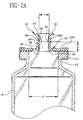
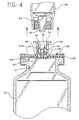
- Resealable bottle assembly 20 preferably features a membrane 40 which is displaceable between an open position ( Figure 3) and a closed position ( Figures 2,4) relative to body 22.
- a fluid path 54 is opened between recess 24 and open top 12 of the bottle, permitting free fluid flow between syringe 60 and the interior of bottle 10.
- fluid path 54 is closed when membrane 40 is returned to its closed position, preventing fluid flow between the recess and the open top of the bottle, and isolating the interior of bottle 10 from the ambient environment.
- membrane 40 which may be formed from an elastomeric material such as various thermoplastic elastomers, natural or synthetic rubbers, or the like, can be configured in a roughly cylindrical, planar manner.
- Membrane 40 includes an edge 46 securable between flat portion 22a of the body and top surface 14 of the bottle, for instance, by the force exerted by crimp cap 48.
- Membrane 40 preferably includes a central area 42 having a width "n" at least equal to width "a" of recess 24. Thus, when the membrane is secured to bottle 10, central area 42 is disposed fully across bottom end 28 of the recess.
- ribs 46a may be incorporated onto edge 46 to provide extra grip between flat portion 22a and annular rim 15.
- ribs 23 and/or ribs 15a may be incorporated on the flat portion and/or annular rim, respectively, for the same purpose.
- membrane 40 may include a flap 247 which is locked beneath annular rim 15 by the action of crimp cap 48.
- the membrane might include a portion 249 wedged into a slot 25 defined in body 22 (Fig. 21d), enhancing the gripping action of the crimp clamp.
- Other variations will be envisioned by the skilled artisan.
- One or more fluid passages may be provided in the membrane to effect fluid communication between the recess and the open top of the bottle.
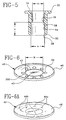
- the one or more fluid passages entail one or more openings 44 are preferably defined on membrane 40 outside of central area 42.
- the one or more openings 44 are located on membrane 40 such that when the membrane is disposed in its closed position ( Figures 2 and 4), sealing rib 30 will contact the membrane in a sealing area 43 defined between central area 42 and the one or more openings, thereby sealing recess 24 from fluid communication with open top 12 of the bottle.
- membrane 40 may be designed or otherwise formed from an appropriate material such that when the membrane is in its closed position, the one or more openings 44 will rest flush against flat portion 22a of the body, further sealing the recess from the open top of the bottle.
- the fluid passages can be formed as pre-pierced slits 44a (See Fig. 6A) provided through membrane 40.
- the fluid passages can be formed as pre-pierced, pinpoint-type punctures 44b. Slits 44a or punctures 44b are configured such that when membrane 40 is disposed in its open position, the slits/punctures will be stretched open to provide fluid access between the open top of the bottle and the recess. Likewise, when the membrane is disposed in its closed position, slits 44a or punctures 44b will close, thereby providing a self-sealing ability to enhance the sealing provided by rib 30.
- a pusher 50 is disposed within recess 24 of body 22.
- Pusher 50 which acts upon membrane 40 to displace the membrane to its open position, features an upper surface 53 and a lower surface 55.
- lower surface 55 is disposed for contact with central area 42 of the membrane, while upper surface 53 is held in the recess by retaining edge 38.
- Retaining edge 38 may prevent, for example, inadvertent withdrawal or displacement of pusher 50 from recess 24, with central area 42 preventing pusher 50 from dropping through open top 12 of the bottle.
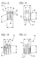
- pusher 50 as illustrated in Figures 2-4 may be formed from a plurality of relatively flat vanes 58 affixed to a cylindrical hub 59.
- Pusher 50 preferably displays a height "d" less than height "b" of recess 24, both to ensure that pusher 50 is securely retained within recess 24 by action of retaining edge 38, and that the pusher will not interfere with sealing between membrane 40 and sealing rib 30.
- Pusher 50 preferably displays a width "e” less than width "a" of recess 24, permitting pusher 50 to move freely in recess 24 without undue interference.
- pusher 50 preferably provides at least one fluid pathway 52 between the opposed end 36 of the luer connector hub and bottom end 28 of the recess.
- cylindrical hub 59 includes an orifice 57 formed along height "d" of the pusher. When pusher 50 is disposed in recess 24, orifice 57 establishes fluid pathway 52 in the recess. Also, any spaces defined between cylindrical hub 59 and respective vanes 58 may serve as secondary fluid pathways 52' (see Figure 8).
- any gap created in the difference in widths "e” and "a” displayed between the pusher and the recess may also establish a fluid pathway through recess 24.
- pusher 80 is defined by a cylindrical body 82 formed having an orifice 81 therethrough for defining fluid pathway 52.
- One or more riblets 84 are configured to radiate from a bottom surface 52' of the fluid pathway.
- Riblets 84 are disposed for contact with central area 42 of the membrane when pusher 80 is disposed in recess 24. Riblets 84 may be spaced apart from one another to define passages 84' in between them, further serving to enhance the efficacy of fluid flow provided by fluid pathway 52.
- pusher 90 is formed from a cylindrical body 92 having one or more channels 96 along length "d" of the pusher that define the fluid pathway.
- One or more upstanding walls 94, provided on cylindrical body 92, may be spaced apart from one another to define secondary channels 95 communicating with channels 96 of cylindrical body 92.
- Figure 11 discloses a pusher 100 somewhat similar to pusher 80 of Figure 9, except that cylindrical body 102 is somewhat shorter than cylindrical body 82 of pusher 80. Riblets 104 like riblets 84 of pusher 80, are disposed for engagement with central area 42 of the membrane, but are formed somewhat longer than riblets 84 of pusher 80.
- Resealable bottle assembly 20 may further include an external seal 70 for preserving the sterility of the various components, inclusive of drug 16, pending use.
- seal 70 features a circular end wall 72, and a cylindrical side wall 74 with an internal thread 76 configured for threadably engaging edge 35 provided with connector end 34 of the luer connector hub.
- a suitable sealing material 78 such as a rubber seal, may be secured to the interior face of circular end wall 72. Accordingly, seal 70 can be threadedly engaged onto luer connector hub 32 and tightened such that sealing material 78 sealingly engages open connector end 34 of the luer connector hub.
- a barrier is established against the passage of contaminants or other unwanted material through connector end 34 of the luer hub which (if otherwise uncovered), would provide communication through recess 24 and, potentially, through open top 12 of bottle 10.
- a conventional cap may be affixed to bottle 10 in a manner to cover luer connector hub 32 and engage a portion of the bottle, for instance, by a tamper evident seal.
- luer lock seal 70 may be removed by unscrewing same from connector end 34 of the luer connector hub. Connector end 34 is thus exposed for insertion of luer tip 62 of syringe 60 (see Figure 3).
- luer tip 62 is urged into contact against upper surface 53 of pusher 50. Under the force exerted by the luer tip, pusher 50 is urged towards the interior of bottle 10.
- a practitioner may now advance a plunger (not shown) associated with syringe 60, thereby supplying fluid to the interior of bottle 10. Thereafter, keeping fluid path 54 open by maintaining the connection between syringe 60 and luer connector hub 32, the practitioner may re-aspirate the now reconstituted drug 16 into syringe 60, causing the reverse fluid flow -- i.e., drug 16 may flow into syringe 60 via: the one or openings 44; gap 61; fluid pathway 52; and luer tip 62. The drug 16 is thus ready for administration by the practitioner, as desired.
- the practitioner may simply reseal bottle 10 by disengaging syringe 60 from luer connector hub 32.
- syringe 60 As exemplified by Figure 4, by removing the force exerted by luer tip 62 upon upper surface 53 of the pusher, membrane 40 will resiliently deflect upwards towards its closed position. Recess 24 will be sealed from open top 12 of the bottle via sealing engagement between membrane 40 and sealing rib 30. Fluid path 54 will thus be closed, isolating the interior of bottle 10 from exposure with the ambient environment, thereby preserving the sterility of any drug 16 still remaining within the bottle.
- openings 44 will also be disposed for contact with flat portion 22a of body 22, further preventing inadvertent fluid flow between recess 24 and open top 12 of the bottle and helping to isolate drug 16 from the ambient environment.
- Figures 12-14 depict a second embodiment 120 of a resealable bottle assembly in accordance with the present invention.
- resealable bottle assembly 120 features a body 122 including a flat portion 122a disposed for contact with top surface 14 of bottle 10.
- An upwardly extending portion 122b defines therein a recess 124, which will be discussed in greater detail hereinbelow.
- a membrane 40 as hereinbefore described is disposed between body 122 and top surface 14 and held in place, for instance, by crimp cap 48.
- body 122 and bottle 10 may be formed as a unitary component.
- a luer connector hub 32 may be supplied separately from body 122 and affixed thereto; otherwise ,it may also be formed in an integral manner with body 122.
- embodiment 120 described herein may include a luer connector seal 70, as previously described.
- Recess 124 features a main portion 126 sandwiched between opposed end walls 128', 129'. While here depicted as sloping, it will be realized by the skilled artisan that end walls 128', 129' could be configured in other manners, such as rounded. Each of end walls 128', 129' terminate in respective top and bottom ends 128, 129 of the recess. Main portion 126 of recess 124 is characterized by a width "g", while each of top and bottom ends 128, 129 have a width "f" less than width "g" of the main portion. Like embodiment 20 previously described, resealable bottle assembly 120 features a sealing rib 130 formed about the periphery of bottom end 129 of recess 124.
- Pusher 150 features an upper end 152 disposed outside of recess 124, thrusting through the top end of the recess towards connector end 34 of the luer connector hub. Bottom end 153 of pusher 150 is disposed for contact with central area 42 of the membrane. As seen in Figure 15, pusher 150 may be formed from vanes 155 disposed at right angles, defining between them fluid pathways 155'. Each of vanes 155 may display a width "h" less than the width "i” displayed by the opening of luer tip 62.
- fluid will be free to flow from syringe 60, and through fluid pathways 155', for exit from recess 124 via a fluid path 154 created between recess 124 and open top 12 of bottle 10 when the membrane is urged into its open position.
- Pusher 150 further includes a protrusion 158 disposed between upper and lower ends 152, 153 of the pusher.
- protrusion 158 includes sloped edges 158a, 158b.
- Protrusion 158 defines a width "J" less than width "G” of main portion 126, but greater than width "F” defined by top and bottom ends 128, 129 of recess 124.
- protrusion 158 prevents pusher 150 from inadvertent withdrawal or removal from recess 124.
- pusher 150 By forming pusher 150 in the elongate manner herein described, it will be apparent that various sizes, lengths, and other characteristics of luer tips or other connection tips associated with the various medical delivery devices employable with the invention can be easily accommodated, absent the need for undue modification to other components associated with the assembly.
- the practitioner By simply varying the dimensions of pusher 150, the practitioner is able to employ resealable bottle assembly 120 with many of the variously sized luer tips 62 as is conventionally available. For instance, where a syringe 60 displays a relatively short luer tip 62, pusher 150 can be lengthened, permitting the shorter luer tip to successfully actuate the membrane to its open position.
- Figure 16 displays an alternate pusher 160 utilizable with resealable bottle assembly 120.
- pusher 160 includes a cylindrical body 164 defining an orifice 163, establishing fluid pathway 162.
- Pusher 160 includes a protrusion 168 formed in an annular manner about cylindrical body 164.
- a lower end 162' of fluid pathway 162 communicates with one or more spaced ribs 166, defining between them channels 166' communicating with fluid pathway 162. 162.
- pusher 160 were configured to eliminate fluid pathway 162-i.e., by eliminating orifice 163 and/or ribs 166, for instance-protrusion 168 might be configured or otherwise dimensioned for sealing contact with either of end walls 128', 129' of the recess, such that fluid flow would occur around protrusion 168 when the protrusion was spaced away from end wall 128'(or 129').
- sealing rib 30 (130) is depicted herein with a squared cross-section.
- the sealing ribs may also display rounded (Fig. 20a) cross-sections, peaked or pointed (Fig. 20b) cross-sections, or any suitable configuration ensuring sealing contact between rib 30 (130) and membrane 40.
- Fig. 20a rounded cross-sections
- Fig. 20b peaked or pointed cross-sections
- Fig. 20c concentric sealing rib
- a sealing rib 200 may be formed as part of the structure of membrane 40 itself (see Figure 6). Sealing rib 200 may be located between the one or more openings 40 and central area 42. Thus, rib 200 will be urged into sealing contact with flat portion 22a (122a) of the respective body when membrane 40 returns to its closed position.
- bottle 10 may be either plastic or glass, as is conventional.
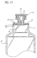
- top surface 14' may be encompassed by the uppermost area of wall 11 surrounding open top 12' (see Figure 17).
- membrane 40 and body 22 are directly affixed to top surface 14', for instance, by welding, adhesives, or mechanical methods of affixation.
- membrane 40 may be formed with them, for instance, by a suitable co-injection process.
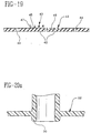
- membrane 40 may be secured across the interface between recess 24" and open top 12" of the bottle, for instance, by supporting edges 46" of membrane 40" in a gap or annulus 17" defined by unitary bottle 10"/body 22" (or 122") (see Figure 18).
- one or more channels 43 may be provided on the central area (See Figure 19). Channels 43 can entail spaces 45 defined between ribs 47 formed on the central area, or channels 49 incorporated in the structure of central area 42.
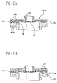
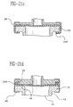
- Fig. 22 illustrates an embodiment of the resealable bottle assembly substantially as hereinbefore described, albeit configured to retain the membrane against the neck of the bottle.
- a body 222 is provided, having a downwardly extending portion 222b that defines a recess 227.
- pusher 250 is disposed in recess 227.
- Downwardly extending portion 222b is configured for insertion into neck portion 213 of bottle 210.
- Membrane 240 includes an annular bead 248 retained between neck portion 213 and a complementary groove 260 formed on downwardly extending portion 222b.
- One or more annular ribs 249 may also be provided on membrane 240 distal of annular bead 248.
- body 222 may be secured to annular rim 215 via a crimp cap, as here shown, body 222 is threadedly secured to annular rim 215 via complementary threads 228, 226 formed on the annular rim and sidewall 227 of the body, respectively.
- membrane 240 rests between the bottom end of the recess and the open top of the bottle for opening and closing of the fluid path. It will be realized that by this configuration, annular bead 248 and, if provided, the one or more annular ribs 249 may also act as a stopper for bottle 210.
Landscapes
- Health & Medical Sciences (AREA)
- Pharmacology & Pharmacy (AREA)
- Life Sciences & Earth Sciences (AREA)
- Animal Behavior & Ethology (AREA)
- General Health & Medical Sciences (AREA)
- Public Health (AREA)
- Veterinary Medicine (AREA)
- Medical Preparation Storing Or Oral Administration Devices (AREA)
- Closures For Containers (AREA)
Claims (15)
- Wiederabdichtbarer Behälteraufbau (20; 120), der enthält:einen Behälter (10) mit einem offenen Oberteil (12), mit einem Innenraum, der mit dem offenen Oberteil fluidmäßig in Verbindung steht, und mit einer oberen Fläche (14), die rund um Teile des Behälters angeordnet ist, die den offenen Oberteil umschließen;einen Körper (22), der neben der oberen Fläche (14) des Behälters (10) angeordnet ist, wobei der Körper (22) eine Ausnehmung (24; 124) bildet, die einen Fluidweg (54) mit dem offenen Oberteil (12) des Behälters besitzt, wobei die Ausnehmung eine Breite, eine Höhe sowie einen Umfang neben dem offenen Oberteil des Behälters besitzt;eine Einrichtung (32-38), um das Fluid mit der Ausnehmung (24; 124) in Verbindung zu bringen, wobei die Einrichtung ein Anschlussende (34), das eine Luer-Verbindungsnabe (32) aufweist, sowie ein gegenüber liegendes Ende (36) besitzt, das am Körper (22) angeordnet ist;eine elastomere Membran (40), die zwischen dem offenen Oberteil (12) des Behälters (10) und der Ausnehmung (24; 124) angeordnet ist, die der Körper (22) bildet, wobei die Membran (40) einen Dichtungsbereich (43) besitzt, der mit dem Umfang der Ausnehmung abgedichtet in Berührung steht und einen oder mehrere Fluidkanäle (44) außerhalb des Dichtungsbereichs (43) bildet, um eine Fluidverbindung zwischen der Ausnehmung (24; 124) und dem offenen Oberteil des Behälters herzustellen, wobei ein verformbarer Teil der Membran (40) zwischen einer abgedichteten Stellung, um den Fluidweg (54) zwischen der Ausnehmung (24; 124) und dem offenen Oberteil (12) des Behälters (10) zu verschließen, und einer offenen Stellung ausgelenkt werden kann, um den Fluidweg (54) zwischen der Ausnehmung und dem offenen Oberteil des Behälters zu öffnen; undein Druckelement (50; 80; 90; 100; 150; 160), das in der Ausnehmung (24; 124) angeordnet ist und zumindest einen Fluidpfad (52) bildet, wobei das Druckelement ein oberes Ende, das für eine Berührung mit einer Injektionsspritze (60) angeordnet ist, die eine Steckermännchen-Luerspitze (62) besitzt, die durch die Luer-Verbindungsnabe (32) des Anschlussendes (34) der Einrichtung (32-38) eingeführt wird, um eine Verbindung herzustellen, sowie ein unters Ende besitzt, das für eine Berührung mit der Membran (40) angeordnet ist, wobei eine Kraft, die von der Steckermännchen-Luerspitze (62) auf das obere Ende des Druckelements (50; 80; 90; 100; 150; 160) ausgeübt wird, das Druckelement gegen die Membran (40) drückt, um den Teil der Membran in die offene Stellung zu drücken, und wobei die Membran (40) in eine normale abgedichtete Stellung zurückkehrt, wenn die Kraft vom Druckelement (50; 80; 90; 100; 150; 160) entfernt wird.
- Wiederabdichtbarer Behälteraufbau gemäß Anspruch 1, wobei die Membran (40) ein Element enthält, das zwischen dem Körper (22) und der oberen Fläche (14) des Behälters (10) gehalten wird.
- Wiederabdichtbarer Behälteraufbau gemäß Anspruch 1, wobei das Druckelement (50; 80; 90; 100) vollständig innerhalb der Ausnehmung (24) angeordnet ist, die vom Körper (22) gebildet wird.
- Wiederabdichtbarer Behälteraufbau gemäß Anspruch 1, wobei das obere Ende des Druckelements (150; 160) durch das gegenüber liegende Ende (36) der Einrichtung (32-38) angeordnet ist, um eine Fluidverbindung herzustellen.
- Wiederabdichtbarer Behälteraufbau gemäß Anspruch 1, wobei der eine oder die mehreren Fluidpfade eine oder mehrere Öffnungen (44) oder einen oder mehrere Schlitze (44a) enthalten.
- Wiederabdichtbarer Behälteraufbau gemäß Anspruch 1, wobei der Aufbau weiters eine Dichtungsrippe (30; 130) enthält, die um zumindest einen Teil des Umfangs der Ausnehmung (24; 124) angeordnet ist, um mit dem Dichtungsbereich (43) der Membran (40) in Berührung zu treten.
- Wiederabdichtbarer Behälteraufbau gemäß Anspruch 1, wobei der Aufbau eine Dichtungsrippe (200) enthält, die auf der Membran (40) angeordnet ist, um mit dem Körper (22) außerhalb jenes Umfangs in Berührung zu treten, der von der Ausnehmung (24; 124) gebildet wird.
- Wiederabdichtbarer Behälteraufbau gemäß Anspruch 1, wobei das Druckelement (50; 80; 90; 100; 150; 160) einen oder mehrere Fluidpfade zwischen dem oberen und dem unteren Ende des Druckelements bildet.
- Wiederabdichtbarer Behälteraufbau gemäß Anspruch 8, wobei zumindest einer des einen oder der mehreren Fluidpfade im Aufbau des Druckelements (50; 80; 90; 100; 150; 160) enthalten ist.
- Wiederabdichtbarer Behälteraufbau gemäß Anspruch 9, wobei der zumindest eine Fluidpfad einen Fluidkanal (52; 96; 155; 162) im Aufbau des Druckelements (50; 80; 90; 100; 150; 160) enthält.
- Wiederabdichtbarer Behälteraufbau gemäß Anspruch 1, wobei die Luer-Verbindungsnabe (32) eine obere Wand (72) sowie eine ringförmige Seitenwand (74) aufweist, die von der oberen Wand vorspringt, wobei die ringförmige Seitenwand (74) eine Anordnung von Innengewinden (76) aufweist, die wahlweise in das Anschlussende (34) der Luer-Verbindungsnabe (32) und eine Dichtung (78) eingreifen können, die zwischen der oberen Wand (72) und dem Anschlussende (34) der Luer-Verbindungsnabe angeordnet sind, um das Anschlussende abdichtend in Eingriff zu bringen.
- Wiederabdichtbarer Behälteraufbau gemäß Anspruch 1, wobei das Druckelement (50; 80; 100; 160) einen zylindrischen Körper aufweist, der eine durchgehende Öffnung (52; 162) besitzt, um einen Fluidpfad zu bilden.
- Wiederabdichtbarer Behälteraufbau gemäß Anspruch 1, wobei das Druckelement (90) einen zylindrischen Körper (92) aufweist, der über die Länge des Druckelements einen oder mehrere erste Kanäle (96) besitzt, die vom Fluidpfad gebildet werden.
- Wiederabdichtbarer Behälteraufbau gemäß Anspruch 12, wobei eine oder mehrere kleine Rippen (84; 104; 166) am Druckelement (90) so ausgebildet sind, dass sie von einer unteren Fläche des Fluidpfads ausgehen, wobei die kleinen Rippen für eine Berührung mit einem Mittelbereich (42) der Membran (40) angeordnet sind, wenn das Druckelement (80; 100; 160) in der Ausnehmung (24; 124) angeordnet ist, oder wobei die kleinen Rippen voneinander beabstandet sind, um zwischen ihnen Wege (84'; 104' ; 166') zu bilden, um den Wirkungsgrad der Fluidströmung zu erhöhen, die der Fluidpfad liefert.
- Wiederabdichtbarer Behälteraufbau gemäß Anspruch 13, wobei eine oder mehrere aufragende Wände (94) am zylindrischen Körper (92) vorgesehen sind, die voneinander beabstandet sind, um zweite Kanäle (95) zu bilden, die mit den ersten Kanälen (96) des zylindrischen Körpers in Verbindung stehen.
Applications Claiming Priority (2)
| Application Number | Priority Date | Filing Date | Title |
|---|---|---|---|
| US53475595A | 1995-09-27 | 1995-09-27 | |
| US534755 | 1995-09-27 |
Publications (2)
| Publication Number | Publication Date |
|---|---|
| EP0765652A1 EP0765652A1 (de) | 1997-04-02 |
| EP0765652B1 true EP0765652B1 (de) | 2002-06-05 |
Family
ID=24131402
Family Applications (1)
| Application Number | Title | Priority Date | Filing Date |
|---|---|---|---|
| EP96114815A Expired - Lifetime EP0765652B1 (de) | 1995-09-27 | 1996-09-16 | Wiederverschliessbare Behälteranordnung mit Membrane und Schieber |
Country Status (6)
| Country | Link |
|---|---|
| US (1) | US6168037B1 (de) |
| EP (1) | EP0765652B1 (de) |
| JP (1) | JP2726035B2 (de) |
| CA (1) | CA2185494A1 (de) |
| DE (1) | DE69621544T2 (de) |
| MX (1) | MX9604176A (de) |
Families Citing this family (88)
| Publication number | Priority date | Publication date | Assignee | Title |
|---|---|---|---|---|
| EP0895466A1 (de) | 1996-04-22 | 1999-02-10 | Abbott Laboratories | Behälterverschlusssystem |
| US5871110A (en) * | 1996-09-13 | 1999-02-16 | Grimard; Jean-Pierre | Transfer assembly for a medicament container having a splashless valve |
| AU6152298A (en) * | 1997-02-07 | 1998-08-26 | Visionary Medical Products, Inc. | Needle-less fluid transfer device and method |
| US7032631B2 (en) * | 2000-02-11 | 2006-04-25 | Medical Instill Technologies, Inc. | Medicament vial having a heat-sealable cap, and apparatus and method for filling the vial |
| US7243689B2 (en) | 2000-02-11 | 2007-07-17 | Medical Instill Technologies, Inc. | Device with needle penetrable and laser resealable portion and related method |
| KR100865601B1 (ko) | 2000-10-23 | 2008-10-27 | 피 페턴트, 인크. | 유체 분배기 및 유체 분배기 충진 방법 |
| US7331944B2 (en) | 2000-10-23 | 2008-02-19 | Medical Instill Technologies, Inc. | Ophthalmic dispenser and associated method |
| WO2003013730A1 (en) * | 2001-08-10 | 2003-02-20 | Gen-Probe Incorporated | Connector for use in combining the contents of a pair of containers |
| US7186241B2 (en) * | 2001-10-03 | 2007-03-06 | Medical Instill Technologies, Inc. | Syringe with needle penetrable and laser resealable stopper |
| WO2003033363A1 (en) * | 2001-10-16 | 2003-04-24 | Medical Instill Technologies, Inc. | Dispenser with sealed chamber and one-way valve for providing metered amounts of substances |
| US7798185B2 (en) | 2005-08-01 | 2010-09-21 | Medical Instill Technologies, Inc. | Dispenser and method for storing and dispensing sterile food product |
| CA2489804C (en) | 2002-06-19 | 2008-03-25 | Medical Instill Technologies, Inc. | Sterile filling machine having needle filling station within e-beam chamber |
| EP1546021B1 (de) * | 2002-08-13 | 2010-10-20 | Medical Instill Technologies, Inc. | Behälter und ventilanordnung zum lagern und abgeben von substanzen und verwandtes verfahren |
| NZ538754A (en) * | 2002-09-03 | 2010-04-30 | Medical Instill Tech Inc | Sealed vial with a reseable stopper and methods of making and filling same |
| EP1631496B1 (de) * | 2003-04-28 | 2014-02-26 | Medical Instill Technologies, Inc. | Behälter mit ventilanordnung zum füllen und abgeben von stoffen und vorrichtung und verfahren zum füllen |
| EP1636091A2 (de) | 2003-05-12 | 2006-03-22 | Medical Instill Technologies, Inc. | Abgabevorrichtung und vorrichtung zum füllen einer abgabevorrichtung |
| MXPA06006962A (es) * | 2003-12-18 | 2007-01-30 | Halkey Roberts Corp | Frasco de acceso sin agua. |
| US20080009822A1 (en) * | 2003-12-18 | 2008-01-10 | Halkey-Roberts Corporation | Needleless access vial |
| US7264142B2 (en) | 2004-01-27 | 2007-09-04 | Medical Instill Technologies, Inc. | Dispenser having variable-volume storage chamber and depressible one-way valve assembly for dispensing creams and other substances |
| US7686235B2 (en) * | 2004-10-26 | 2010-03-30 | Roberts James C | Check valve assembly for controlling the flow of pressurized fluids |
| US20060086833A1 (en) * | 2004-10-26 | 2006-04-27 | Roberts James C | Check valve assembly for sprinkler head |
| US8162170B1 (en) | 2005-04-19 | 2012-04-24 | Massad Gary L | Tip resistant beverage container providing a tip lip |
| WO2007027567A1 (en) * | 2005-08-29 | 2007-03-08 | Mallinckrodt Inc. | Medical fluid container system having needle-free connection |
| WO2007042204A1 (de) * | 2005-10-07 | 2007-04-19 | Ammann Rainer | Verschluss |
| US7966746B2 (en) * | 2006-04-24 | 2011-06-28 | Medical Instill Technologies, LLC | Needle penetrable and laser resealable lyophilization method |
| ES2425579T3 (es) * | 2006-05-25 | 2013-10-16 | Bayer Healthcare, Llc | Dispositivo de reconstitución |
| EP2188004A4 (de) | 2007-08-21 | 2015-06-17 | Yukon Medical Llc | Ampullenzugangs- und injektionssystem |
| WO2009146088A1 (en) * | 2008-04-01 | 2009-12-03 | Yukon Medical, Llc | Dual container fluid transfer device |
| IL201323A0 (en) | 2009-10-01 | 2010-05-31 | Medimop Medical Projects Ltd | Fluid transfer device for assembling a vial with pre-attached female connector |
| IL202070A0 (en) | 2009-11-12 | 2010-06-16 | Medimop Medical Projects Ltd | Inline liquid drug medical device |
| IL202069A0 (en) | 2009-11-12 | 2010-06-16 | Medimop Medical Projects Ltd | Fluid transfer device with sealing arrangement |
| US9296531B2 (en) * | 2010-01-12 | 2016-03-29 | Medela Holding Ag | Container with sealed cap and venting system |
| DK2512398T3 (da) | 2010-02-24 | 2014-10-13 | Medimop Medical Projects Ltd | Overføringsindretning for flydende medikament med udluftet ampuladapter |
| EP2512399B1 (de) | 2010-02-24 | 2015-04-08 | Medimop Medical Projects Ltd. | Flüssigkeitstransportanordnung mit belüftungsanordnung |
| USD655017S1 (en) | 2010-06-17 | 2012-02-28 | Yukon Medical, Llc | Shroud |
| IL209290A0 (en) | 2010-11-14 | 2011-01-31 | Medimop Medical Projects Ltd | Inline liquid drug medical device having rotary flow control member |
| JP5162651B2 (ja) * | 2010-12-20 | 2013-03-13 | 富士ゼロックス株式会社 | 液体供給装置 |
| GB2487206B (en) * | 2011-01-12 | 2015-12-16 | White Horse Innovations Ltd | Nozzle for fluid container |
| IL212420A0 (en) | 2011-04-17 | 2011-06-30 | Medimop Medical Projects Ltd | Liquid drug transfer assembly |
| USD681230S1 (en) | 2011-09-08 | 2013-04-30 | Yukon Medical, Llc | Shroud |
| IL215699A0 (en) | 2011-10-11 | 2011-12-29 | Medimop Medical Projects Ltd | Liquid drug reconstitution assemblage for use with iv bag and drug vial |
| USD720451S1 (en) | 2012-02-13 | 2014-12-30 | Medimop Medical Projects Ltd. | Liquid drug transfer assembly |
| USD737436S1 (en) | 2012-02-13 | 2015-08-25 | Medimop Medical Projects Ltd. | Liquid drug reconstitution assembly |
| IL219065A0 (en) | 2012-04-05 | 2012-07-31 | Medimop Medical Projects Ltd | Fluid transfer device with manual operated cartridge release arrangement |
| USD769444S1 (en) | 2012-06-28 | 2016-10-18 | Yukon Medical, Llc | Adapter device |
| IL221635A0 (en) | 2012-08-26 | 2012-12-31 | Medimop Medical Projects Ltd | Drug vial mixing and transfer device for use with iv bag and drug vial |
| IL221634A0 (en) | 2012-08-26 | 2012-12-31 | Medimop Medical Projects Ltd | Universal drug vial adapter |
| JP5868555B2 (ja) | 2012-09-13 | 2016-02-24 | メディモップ・メディカル・プロジェクツ・リミテッド | 入れ子式雌薬瓶アダプタ |
| USD734868S1 (en) | 2012-11-27 | 2015-07-21 | Medimop Medical Projects Ltd. | Drug vial adapter with downwardly depending stopper |
| IL225734A0 (en) | 2013-04-14 | 2013-09-30 | Medimop Medical Projects Ltd | A ready-to-use medicine vial device including a medicine vial closure, and a medicine vial closure for it |
| BR112015027555B1 (pt) | 2013-05-10 | 2022-02-01 | Medimop Medical Projects Ltd | Dispositivo médico para uso com uma seringa sem agulha, um frasco e um veículo líquido para preencher a seringa sem agulha com uma solução de injeção para injeção em um paciente |
| USD765837S1 (en) | 2013-08-07 | 2016-09-06 | Medimop Medical Projects Ltd. | Liquid transfer device with integral vial adapter |
| USD767124S1 (en) | 2013-08-07 | 2016-09-20 | Medimop Medical Projects Ltd. | Liquid transfer device with integral vial adapter |
| KR200486088Y1 (ko) | 2013-08-07 | 2018-04-02 | 메디모프 메디컬 프로젝트스 리미티드. | 주입 액체 용기와 함께 사용하기 위한 액체 전달 장치 |
| EP3119469A4 (de) * | 2014-03-18 | 2018-04-04 | I-V Access Technology, Inc. | Intravenöser katheter mit druckaktiviertem ventil |
| USD757933S1 (en) | 2014-09-11 | 2016-05-31 | Medimop Medical Projects Ltd. | Dual vial adapter assemblage |
| WO2016110838A1 (en) | 2015-01-05 | 2016-07-14 | Medimop Medical Projects Ltd | Dual vial adapter assemblages with quick release drug vial adapter for ensuring correct usage |
| BR112018000062B1 (pt) | 2015-07-16 | 2022-05-03 | Medimop Medical Projects Ltd | Dispositivo de transferência de fármaco líquido para encaixe telescópico flexível seguro em frasco de injeção |
| USD801522S1 (en) | 2015-11-09 | 2017-10-31 | Medimop Medical Projects Ltd. | Fluid transfer assembly |
| EP3380058B1 (de) | 2015-11-25 | 2020-01-08 | West Pharma Services IL, Ltd. | Dualphiolenadapteranordnung mit arzneimittelphiolenadapter mit selbstverschliessendem zugangsventil |
| US12447112B2 (en) | 2016-02-24 | 2025-10-21 | Avent, Inc. | Fluid transfer connector |
| WO2017147233A2 (en) | 2016-02-24 | 2017-08-31 | Neomed, Inc. | Fluid transfer connector |
| HUE054412T2 (hu) | 2016-05-16 | 2021-09-28 | Haemonetics Corp | Tömítõ nélküli plazmapalack és felsõrész ugyanahhoz |
| US11648179B2 (en) | 2016-05-16 | 2023-05-16 | Haemonetics Corporation | Sealer-less plasma bottle and top for same |
| IL245803A0 (en) | 2016-05-24 | 2016-08-31 | West Pharma Services Il Ltd | Devices with two vial adapters include an aerated drug vial adapter and an aerated liquid vial adapter |
| IL245800A0 (en) | 2016-05-24 | 2016-08-31 | West Pharma Services Il Ltd | A device with two vial adapters includes two identical vial adapters |
| IL246073A0 (en) | 2016-06-06 | 2016-08-31 | West Pharma Services Il Ltd | A fluid transport device for use with a slide-driven piston medicine pump cartridge |
| IL247376A0 (en) | 2016-08-21 | 2016-12-29 | Medimop Medical Projects Ltd | Injector assembly |
| USD832430S1 (en) | 2016-11-15 | 2018-10-30 | West Pharma. Services IL, Ltd. | Dual vial adapter assemblage |
| IL249408A0 (en) | 2016-12-06 | 2017-03-30 | Medimop Medical Projects Ltd | Liquid transfer device for use with infusion liquid container and pincers-like hand tool for use therewith for releasing intact drug vial therefrom |
| IL251458A0 (en) | 2017-03-29 | 2017-06-29 | Medimop Medical Projects Ltd | Liquid drug delivery devices are user-operated for use in pre-prepared liquid drug delivery assemblies (rtu) |
| WO2018213524A1 (en) | 2017-05-17 | 2018-11-22 | Klim-Loc, Llc | Devices and methods for needleless extraction and administration of contents from vials |
| IL254802A0 (en) | 2017-09-29 | 2017-12-31 | Medimop Medical Projects Ltd | A device with two vial adapters includes two identical perforated vial adapters |
| HUE067821T2 (hu) * | 2018-05-22 | 2024-11-28 | Haemonetics Corp | Tömítõanyagmentes plazmapalack és fedél hozzá |
| USD903864S1 (en) | 2018-06-20 | 2020-12-01 | West Pharma. Services IL, Ltd. | Medication mixing apparatus |
| JP1630477S (de) | 2018-07-06 | 2019-05-07 | ||
| GB201814977D0 (en) * | 2018-09-14 | 2018-10-31 | Sellars Michael John | Method and apparatus for refilling a container |
| USD923812S1 (en) | 2019-01-16 | 2021-06-29 | West Pharma. Services IL, Ltd. | Medication mixing apparatus |
| JP1648075S (de) | 2019-01-17 | 2019-12-16 | ||
| WO2020148748A1 (en) | 2019-01-18 | 2020-07-23 | West Pharma. Services IL, Ltd. | Liquid transfer devices for use with intravenous (iv) bottles |
| EP3917486B1 (de) | 2019-01-31 | 2023-03-08 | West Pharma. Services IL, Ltd | Flüssigkeitstransfervorrichtung |
| CN113677382B (zh) | 2019-04-09 | 2023-06-09 | 西医药服务以色列有限公司 | 具有集成式注射器的液体输送装置 |
| IL277446B2 (en) | 2019-04-30 | 2024-02-01 | West Pharma Services Il Ltd | Device for transporting liquids with a double-canal infusion tip |
| US12104990B2 (en) * | 2019-12-16 | 2024-10-01 | Shane Park | Apparatus for collecting and storing fluid samples from vehicles and machinery |
| USD956958S1 (en) | 2020-07-13 | 2022-07-05 | West Pharma. Services IL, Ltd. | Liquid transfer device |
| US11007120B1 (en) | 2020-10-15 | 2021-05-18 | Klim-Loc, Llc | Devices and methods for needleless and needled extraction of contents from vials |
| US11554894B2 (en) | 2020-12-04 | 2023-01-17 | Sonoco Development, Inc. | Peelable resealable membrane for containers |
| US11607525B1 (en) | 2022-06-30 | 2023-03-21 | I-V Access Technology, Inc. | Methods and devices for vascular access |
Family Cites Families (32)
| Publication number | Priority date | Publication date | Assignee | Title |
|---|---|---|---|---|
| US2607503A (en) | 1946-03-04 | 1952-08-19 | Mid West Bottle Cap Co | Bottle closure |
| FR1071487A (fr) | 1953-02-26 | 1954-09-01 | Aiguille pour la préparation des solutions antibiotiques et le remplissage des seringues | |
| US2953132A (en) | 1955-10-27 | 1960-09-20 | Baxter Laboratories Inc | Parenteral solution equipment |
| US3164303A (en) * | 1961-12-04 | 1965-01-05 | Semco Res Inc | Storage and mixing cartridge |
| US3206080A (en) | 1962-07-23 | 1965-09-14 | Abbott Lab | Dispensing assembly |
| US3356093A (en) * | 1965-03-25 | 1967-12-05 | Oel Inc | Valved catheter |
| US3357427A (en) * | 1965-04-21 | 1967-12-12 | John M Wittke | Aerosol introducer device for dispensing a measured charge of therapeutic composition into body cavities |
| FR1487413A (fr) | 1966-05-20 | 1967-07-07 | Perfectionnements aux bouchons-verseurs | |
| CH501172A (de) | 1967-12-01 | 1970-12-31 | Beleggingsmij Ind N V | Membraneverschluss |
| US3674028A (en) | 1969-06-04 | 1972-07-04 | Ims Ltd | Multi-mix |
| US3838689A (en) * | 1970-11-04 | 1974-10-01 | M Cohen | Disposable syringe with slit valve |
| US3779371A (en) * | 1972-03-13 | 1973-12-18 | W Rovinski | Package of separated materials to be mixed |
| US4210255A (en) * | 1978-06-30 | 1980-07-01 | The Continental Group, Inc. | Self-venting end unit for pressure packaging |
| EP0198675B2 (de) * | 1985-04-11 | 1994-04-13 | CEM Corporation | Selbstregulierendes Ventil in einem Mikrowellen- und Behältersystem |
| DE3618158A1 (de) | 1986-05-30 | 1987-12-03 | Schiwa Gmbh | Konnektor fuer einen infusionsbehaelter |
| JPS6346359U (de) * | 1986-09-12 | 1988-03-29 | ||
| US4822351A (en) | 1987-03-25 | 1989-04-18 | Ims Limited | Powder spike holder |
| CA2006584C (en) | 1988-12-27 | 1998-11-10 | Gabriel Meyer | Storage and transfer bottle for storing a component of a medicinal substance |
| EP0448656B1 (de) | 1989-09-14 | 1993-12-01 | Becton Dickinson France S.A. | Länglicher behälter mit zwei getrennten kammern auf der gleichen längsachse |
| ATE95415T1 (de) | 1989-11-13 | 1993-10-15 | Medicorp Holding | Vorratsbehaelter fuer einen bestandteil einer medikamentenloesung. |
| ATE111725T1 (de) | 1990-01-08 | 1994-10-15 | Becton Dickinson France | Aufbewahrungs- und umfüllflasche mit doppelter kammer. |
| JPH04115127A (ja) | 1990-09-06 | 1992-04-16 | Oki Electric Ind Co Ltd | 残響音測定付加装置 |
| US5352196A (en) * | 1990-11-19 | 1994-10-04 | Habley Medical Technology Corporation | Mixing vial |
| JP2530771Y2 (ja) * | 1991-03-29 | 1997-03-26 | 凸版印刷株式会社 | 液体注出栓 |
| US5360413A (en) | 1991-12-06 | 1994-11-01 | Filtertek, Inc. | Needleless access device |
| US5423791A (en) * | 1992-03-31 | 1995-06-13 | Bartlett; J. Mark | Valve device for medical fluid transfer |
| US5425465A (en) * | 1993-03-03 | 1995-06-20 | Healy; Patrick M. | Valved medication container |
| US5494170A (en) | 1993-05-06 | 1996-02-27 | Becton Dickinson And Company | Combination stopper-shield closure |
| AU7474094A (en) | 1993-08-03 | 1995-02-28 | I-Flow Corporation | Valve for filling iv solution bag |
| US5620434A (en) | 1994-03-14 | 1997-04-15 | Brony; Seth K. | Medicine vial link for needleless syringes |
| US5702019A (en) * | 1995-09-27 | 1997-12-30 | Becton Dickinson France S.A. | Vial having resealable membrane assembly activated by a medical delivery device |
| US5871110A (en) * | 1996-09-13 | 1999-02-16 | Grimard; Jean-Pierre | Transfer assembly for a medicament container having a splashless valve |
-
1996
- 1996-09-13 CA CA 2185494 patent/CA2185494A1/en not_active Abandoned
- 1996-09-16 EP EP96114815A patent/EP0765652B1/de not_active Expired - Lifetime
- 1996-09-16 DE DE69621544T patent/DE69621544T2/de not_active Expired - Lifetime
- 1996-09-19 MX MX9604176A patent/MX9604176A/es unknown
- 1996-09-27 JP JP25697996A patent/JP2726035B2/ja not_active Expired - Lifetime
-
1997
- 1997-08-04 US US08/906,011 patent/US6168037B1/en not_active Expired - Lifetime
Also Published As
| Publication number | Publication date |
|---|---|
| US6168037B1 (en) | 2001-01-02 |
| CA2185494A1 (en) | 1997-03-28 |
| JP2726035B2 (ja) | 1998-03-11 |
| DE69621544D1 (de) | 2002-07-11 |
| DE69621544T2 (de) | 2002-09-26 |
| JPH09104461A (ja) | 1997-04-22 |
| EP0765652A1 (de) | 1997-04-02 |
| MX9604176A (es) | 1997-03-29 |
Similar Documents
| Publication | Publication Date | Title |
|---|---|---|
| EP0765652B1 (de) | Wiederverschliessbare Behälteranordnung mit Membrane und Schieber | |
| EP0765653B1 (de) | Wiederverschliessbare, durch eine medizinische Abgabevorrichtung aktivierbare, Behälteranordnung | |
| US5871110A (en) | Transfer assembly for a medicament container having a splashless valve | |
| EP1169075B1 (de) | Spritze mit originalitätsicherung | |
| JP4884584B2 (ja) | 瓶および医療容器用の移送セット | |
| CA1071585A (en) | Mixing vial | |
| US4392851A (en) | In-line transfer unit | |
| EP1011604B1 (de) | Behälterverschluss mit zerbrechbarer dichtung und verbindung für eine fluidtransfereinrichtung | |
| US6090093A (en) | Connector assembly for a vial having a flexible collar | |
| KR100227053B1 (ko) | 약제 수용용기 및 약제 주사 세트 | |
| EP1616808A1 (de) | Flüssigkeitsübertragungsvorrichtung | |
| EP0765651B1 (de) | Phiole mit wiederverschliessbarer Verbindungsanordnung mit Membrane und einer Flüssigkeitszugangsvorrichtung mit mehreren Konfigurationen | |
| EP0904763B1 (de) | Verbinder mit Verriegelungsring für eine Phiole | |
| MXPA97007012A (es) | Un ensamble de transferencia para un recipiente de medicamento que tiene una valvula sin salpicadura | |
| HK1032208A (en) | Pre-filled tamper evident syringe assembly |
Legal Events
| Date | Code | Title | Description |
|---|---|---|---|
| PUAI | Public reference made under article 153(3) epc to a published international application that has entered the european phase |
Free format text: ORIGINAL CODE: 0009012 |
|
| AK | Designated contracting states |
Kind code of ref document: A1 Designated state(s): BE DE ES FR GB IT SE |
|
| RTI1 | Title (correction) | ||
| 17P | Request for examination filed |
Effective date: 19971001 |
|
| 17Q | First examination report despatched |
Effective date: 19991112 |
|
| GRAG | Despatch of communication of intention to grant |
Free format text: ORIGINAL CODE: EPIDOS AGRA |
|
| RTI1 | Title (correction) |
Free format text: RESEALABLE CONTAINER ASSEMBLY HAVING A MEMBRANE AND PUSHER |
|
| GRAG | Despatch of communication of intention to grant |
Free format text: ORIGINAL CODE: EPIDOS AGRA |
|
| GRAH | Despatch of communication of intention to grant a patent |
Free format text: ORIGINAL CODE: EPIDOS IGRA |
|
| GRAH | Despatch of communication of intention to grant a patent |
Free format text: ORIGINAL CODE: EPIDOS IGRA |
|
| GRAA | (expected) grant |
Free format text: ORIGINAL CODE: 0009210 |
|
| AK | Designated contracting states |
Kind code of ref document: B1 Designated state(s): BE DE ES FR GB IT SE |
|
| PG25 | Lapsed in a contracting state [announced via postgrant information from national office to epo] |
Ref country code: IT Free format text: LAPSE BECAUSE OF FAILURE TO SUBMIT A TRANSLATION OF THE DESCRIPTION OR TO PAY THE FEE WITHIN THE PRESCRIBED TIME-LIMIT;WARNING: LAPSES OF ITALIAN PATENTS WITH EFFECTIVE DATE BEFORE 2007 MAY HAVE OCCURRED AT ANY TIME BEFORE 2007. THE CORRECT EFFECTIVE DATE MAY BE DIFFERENT FROM THE ONE RECORDED. Effective date: 20020605 Ref country code: BE Free format text: LAPSE BECAUSE OF FAILURE TO SUBMIT A TRANSLATION OF THE DESCRIPTION OR TO PAY THE FEE WITHIN THE PRESCRIBED TIME-LIMIT Effective date: 20020605 |
|
| REG | Reference to a national code |
Ref country code: GB Ref legal event code: FG4D |
|
| REF | Corresponds to: |
Ref document number: 69621544 Country of ref document: DE Date of ref document: 20020711 |
|
| PG25 | Lapsed in a contracting state [announced via postgrant information from national office to epo] |
Ref country code: SE Free format text: LAPSE BECAUSE OF FAILURE TO SUBMIT A TRANSLATION OF THE DESCRIPTION OR TO PAY THE FEE WITHIN THE PRESCRIBED TIME-LIMIT Effective date: 20020905 |
|
| PG25 | Lapsed in a contracting state [announced via postgrant information from national office to epo] |
Ref country code: GB Free format text: LAPSE BECAUSE OF NON-PAYMENT OF DUE FEES Effective date: 20020916 |
|
| ET | Fr: translation filed | ||
| PG25 | Lapsed in a contracting state [announced via postgrant information from national office to epo] |
Ref country code: ES Free format text: LAPSE BECAUSE OF FAILURE TO SUBMIT A TRANSLATION OF THE DESCRIPTION OR TO PAY THE FEE WITHIN THE PRESCRIBED TIME-LIMIT Effective date: 20021220 |
|
| PLBE | No opposition filed within time limit |
Free format text: ORIGINAL CODE: 0009261 |
|
| STAA | Information on the status of an ep patent application or granted ep patent |
Free format text: STATUS: NO OPPOSITION FILED WITHIN TIME LIMIT |
|
| GBPC | Gb: european patent ceased through non-payment of renewal fee |
Effective date: 20020916 |
|
| 26N | No opposition filed |
Effective date: 20030306 |
|
| PGFP | Annual fee paid to national office [announced via postgrant information from national office to epo] |
Ref country code: FR Payment date: 20140917 Year of fee payment: 19 |
|
| PGFP | Annual fee paid to national office [announced via postgrant information from national office to epo] |
Ref country code: DE Payment date: 20140929 Year of fee payment: 19 |
|
| REG | Reference to a national code |
Ref country code: DE Ref legal event code: R119 Ref document number: 69621544 Country of ref document: DE |
|
| REG | Reference to a national code |
Ref country code: FR Ref legal event code: ST Effective date: 20160531 |
|
| PG25 | Lapsed in a contracting state [announced via postgrant information from national office to epo] |
Ref country code: DE Free format text: LAPSE BECAUSE OF NON-PAYMENT OF DUE FEES Effective date: 20160401 |
|
| PG25 | Lapsed in a contracting state [announced via postgrant information from national office to epo] |
Ref country code: FR Free format text: LAPSE BECAUSE OF NON-PAYMENT OF DUE FEES Effective date: 20150930 |