EP0765204B1 - Vorrichtung zum putzen von schweissroboterköpfen - Google Patents
Vorrichtung zum putzen von schweissroboterköpfen Download PDFInfo
- Publication number
- EP0765204B1 EP0765204B1 EP95923632A EP95923632A EP0765204B1 EP 0765204 B1 EP0765204 B1 EP 0765204B1 EP 95923632 A EP95923632 A EP 95923632A EP 95923632 A EP95923632 A EP 95923632A EP 0765204 B1 EP0765204 B1 EP 0765204B1
- Authority
- EP
- European Patent Office
- Prior art keywords
- vessel
- liquid
- casing
- shaft
- tool
- Prior art date
- Legal status (The legal status is an assumption and is not a legal conclusion. Google has not performed a legal analysis and makes no representation as to the accuracy of the status listed.)
- Expired - Lifetime
Links
- 238000003466 welding Methods 0.000 title claims abstract description 33
- 238000004140 cleaning Methods 0.000 title claims abstract description 15
- 239000007788 liquid Substances 0.000 claims abstract description 21
- 238000003801 milling Methods 0.000 claims description 12
- 239000003599 detergent Substances 0.000 claims description 5
- 238000005406 washing Methods 0.000 claims description 5
- 239000000463 material Substances 0.000 abstract description 9
- 239000007789 gas Substances 0.000 description 31
- 239000007921 spray Substances 0.000 description 8
- 230000000694 effects Effects 0.000 description 4
- 238000000034 method Methods 0.000 description 4
- 238000010276 construction Methods 0.000 description 2
- 238000001816 cooling Methods 0.000 description 2
- 239000011261 inert gas Substances 0.000 description 2
- 230000003647 oxidation Effects 0.000 description 2
- 238000007254 oxidation reaction Methods 0.000 description 2
- 230000005019 pattern of movement Effects 0.000 description 2
- 238000003756 stirring Methods 0.000 description 2
- HSFWRNGVRCDJHI-UHFFFAOYSA-N Acetylene Chemical compound C#C HSFWRNGVRCDJHI-UHFFFAOYSA-N 0.000 description 1
- 238000007796 conventional method Methods 0.000 description 1
- 239000003517 fume Substances 0.000 description 1
- 238000007654 immersion Methods 0.000 description 1
- 239000000155 melt Substances 0.000 description 1
- 238000012986 modification Methods 0.000 description 1
- 230000004048 modification Effects 0.000 description 1
- 230000000149 penetrating effect Effects 0.000 description 1
- 239000002893 slag Substances 0.000 description 1
- 229910001220 stainless steel Inorganic materials 0.000 description 1
- 239000010935 stainless steel Substances 0.000 description 1
- 238000002604 ultrasonography Methods 0.000 description 1
- XLYOFNOQVPJJNP-UHFFFAOYSA-N water Substances O XLYOFNOQVPJJNP-UHFFFAOYSA-N 0.000 description 1
Images

Classifications
-
- B—PERFORMING OPERATIONS; TRANSPORTING
- B23—MACHINE TOOLS; METAL-WORKING NOT OTHERWISE PROVIDED FOR
- B23K—SOLDERING OR UNSOLDERING; WELDING; CLADDING OR PLATING BY SOLDERING OR WELDING; CUTTING BY APPLYING HEAT LOCALLY, e.g. FLAME CUTTING; WORKING BY LASER BEAM
- B23K9/00—Arc welding or cutting
- B23K9/32—Accessories
-
- B—PERFORMING OPERATIONS; TRANSPORTING
- B08—CLEANING
- B08B—CLEANING IN GENERAL; PREVENTION OF FOULING IN GENERAL
- B08B3/00—Cleaning by methods involving the use or presence of liquid or steam
- B08B3/04—Cleaning involving contact with liquid
- B08B3/10—Cleaning involving contact with liquid with additional treatment of the liquid or of the object being cleaned, e.g. by heat, by electricity or by vibration
- B08B3/12—Cleaning involving contact with liquid with additional treatment of the liquid or of the object being cleaned, e.g. by heat, by electricity or by vibration by sonic or ultrasonic vibrations
-
- B—PERFORMING OPERATIONS; TRANSPORTING
- B23—MACHINE TOOLS; METAL-WORKING NOT OTHERWISE PROVIDED FOR
- B23K—SOLDERING OR UNSOLDERING; WELDING; CLADDING OR PLATING BY SOLDERING OR WELDING; CUTTING BY APPLYING HEAT LOCALLY, e.g. FLAME CUTTING; WORKING BY LASER BEAM
- B23K9/00—Arc welding or cutting
- B23K9/24—Features related to electrodes
- B23K9/26—Accessories for electrodes, e.g. ignition tips
-
- B—PERFORMING OPERATIONS; TRANSPORTING
- B23—MACHINE TOOLS; METAL-WORKING NOT OTHERWISE PROVIDED FOR
- B23K—SOLDERING OR UNSOLDERING; WELDING; CLADDING OR PLATING BY SOLDERING OR WELDING; CUTTING BY APPLYING HEAT LOCALLY, e.g. FLAME CUTTING; WORKING BY LASER BEAM
- B23K9/00—Arc welding or cutting
- B23K9/32—Accessories
- B23K9/328—Cleaning of weld torches, i.e. removing weld-spatter; Preventing weld-spatter, e.g. applying anti-adhesives
Definitions
- the present invention relates to an apparatus for cleaning the heads of welding robots.
- Welding robots are used generally within the workshop industry. This applies primarily to MIG-welding and MAG-welding.
- a welding robot is programmed to follow a certain pattern of movements, i.e. the robot head is arranged to follow a given pattern of movements.
- a workpiece to be welded by the robot is positioned accurately in relation to the robot, such that the workpiece will be located in a predetermined position in relation to the robot. As the robot head moves through the predetermined movement pattern, it will move in a predetermined manner in relation to the workpiece.
- the robot head In welding operations, the robot head carries a welding head.
- the robot is thus able to move the welding head to those locations and along those edges or corresponding surfaces where welding is to be performed.
- a welding head includes a gas casing which includes a central passageway for the delivery of welding gas.
- the gas is an inert gas and is ejected onto the weld location to prevent oxidation of the melt and also oxidation of those parts of the workpieces that are heated to high temperatures in the welding process.
- the gas casing passageway has a funnel-shaped orifice.
- An electrical contact nozzle is provided in the gas-casing passageway and has a central channel through which welding rod is advanced to the welding location. The forward end of the nozzle terminates short of the orifice of the gas casing opening and is concentrical therewith. The nozzle is connected to one terminal of the welding unit voltage source and the workpiece is connected to the other terminal of said source.
- the rings of weld-spray that build-up on the welding head and said edge surfaces are electrically conductive and result in spark-over between the rings and the workpieces, whereas the intention is for spark-over to take place between the weld electrode and the workpieces. This results in welding interruptions.
- the ring may also prevent sufficient gas from being delivered to the weld location through the gas casing, resulting in a poor quality weld.
- the aforesaid ring is built-up to an unacceptable size typically in from five to ten minutes, meaning that the gas casing must be cleaned relatively often.
- the gas casing is cleaned by placing the gas-casing opening on a milling tool and milling away the ring mechanically.
- the ring is often seated very firmly on the gas casing and removal of the ring results in the removal of material from the gas casing by virtue of the ring loosening from the casing and being whirled round in contact with the casing by the milling tool, therewith causing wear to the casing.
- the task of removing the ring with the aid of other hand-operated tools, such as cutting nippers, for instance, is also time-consuming.
- the interior of the gas casing and the electrical contact nozzle are cleaned with the aid of compressed air, although the result is not always satisfactory.
- the welding equipment may also include water-cooled gas casings, which are provided with internal cooling channels. Repeated cleaning of the gas casings with subsequent removal of material therefrom may result in the removal of so much material as to open the cooling channels so that the water conducted therethrough will spray out. This results in interruptions in the welding operation.
- DE-B-1064779 discloses an apparatus for cleaning objects, including an open vessel which has connected thereto an ultrasonic generator, which functions to generate ultrasonic waves in a liquid contained in the vessel, where the vessel has mounted therein a rotary device, which is located beneath the upper surface of the liquid.
- the objects to be cleaned are mounted onto the rotary device and are subject to pulses of ultrasonic energy.
- the present invention satisfies the above mentioned desiderata and provides an apparatus for cleaning the gas casing and the electrical contact nozzle quickly and with much less wear on the casing in the proximity of its opening than that experienced with conventional cleaning processes.
- the present invention thus relates to an apparatus for cleaning the heads of electrical welding robots as defined by claim 1.
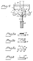
- Figures 1, 2 and 4 illustrate an apparatus for cleaning the heads of electrical welding robots, said heads including a gas casing and an electrical contact nozzle.
- the apparatus includes an open vessel 1 which has connected thereto one or more ultrasonic generators 2, 3 for generating ultrasonic waves in a liquid 4 present in the vessel 1.
- the ultrasonic generators are of a conventional kind and of the type used to generate ultrasonic waves in a liquid for cleaning purposes, in a known manner.
- the vessel 1 is preferably made of stainless steel.
- there is mounted in the vessel a rotary device which is located beneath the upper surface level of the liquid. This surface level is shown by the undulating line 5 in Figure 4.
- the rotary device functions to stir the modes, i.e. standing waves are disturbed in the liquid. This has been found to provide a markedly improved cleaning effect.
- the vessel 1 is conical in shape with the cone apex 6 facing downwards.
- the outer mantle surface of the cone is provided with a plurality of flat sidepieces 7-12.
- An ultrasound generator 2, 3 is mounted on each of three or more of the flat sidepieces 7-12, to generate ultrasonic waves in the liquid.
- the vessel 1 includes six sidepieces with an ultrasonic generator placed on each alternate sidepiece, i.e. an embodiment which includes a total of three generators.
- the side surfaces define an angle v with a plane which extends perpendicular to the longitudinal axis 13 of the vessel and the ultrasonic generators are so positioned on respective side surfaces that respective normals 14, 15 of said side surfaces departing from respective ultrasonic generators will coincide with a point 16 on the longitudinal axis of the vessel 1 beneath the surface 5 of the liquid. As a result, strong interference takes place between the ultrasonic waves at the point 16.
- a shaft 17 extends through a penetrating hole 16' in the bottom of the vessel 1 and carries a tool attachment device 18 on the end thereof located in the vessel.
- An electric motor 48 which drives the shaft 17 is coupled to the other end of the shaft.
- the shaft 17 is rotated at a speed of 50 to 500 r.p.m., preferably about 180 r.p.m.
- the tool attachment device 18 has the form of a plate 19 which is positioned at right angles to the shaft 17 and the upper side 20 of which is provided with tool-mounting means.
- the tool attachment device 18 is preferably fitted detachably to the shaft 17.
- the upper part 21 of the shaft 17 has a square cross-sectional shape, for instance.
- the attachment device will include a sleeve 22 which projects down from the plate 19 and which has an internal hole of corresponding cross-section. When the sleeve 22 is fitted onto the upper part 21 of the shaft, the two parts will be in engagement for rotation of the tool.
- the tool is comprised of one or more brushes and/or a milling tool. Examples of such tools are shown in Figures 5a-5c.
- Figure 5a shows a steel-wire brush 23 fitted on a base plate 24.
- Figure 5b shows a milling tool 25 having upstanding cutting edges 26.
- the outer side of the cutting edges is intended to abut the inside of a ring of weld spray adjacent the opening of a gas casing.
- the milling tool is mounted on a base plate 27.
- the milling tool may have a form which corresponds to the form typically used to clean-off rings of weld spray.
- Figure 5c shows another cutting tool 28 having an upwardly rounded cutting edge 29 which is intended to abut the ring of weld spray in the same way as the milling tool.
- This cutting tool is mounted on a base plate 30.
- the tool base plates 24, 27, 30 are fitted to the plate 20 of the tool attachment device in a manner which will prevent rotation of the base plates on the plate.
- the plate 20 may be provided with a number of upstanding pegs 31-33 which are received in corresponding holes 34-36 in the base plates 24, 27, 30.
- FIG 3 illustrates schematically a conventional gas casing 37 fitted to a robot head.
- the casing includes a sleeve 38 and an electrical contact nozzle 39.
- the nozzle 39 is screwed onto a pipe (not shown) and when fitted takes the position shown in Figure 3 relative to the sleeve 38.
- the nozzle has provided therein a channel 40 in which welding rod 41 is advanced. As the welding rod is consumed, the rod is advanced down in the direction of the arrow 42. Inert gas flows down between the sleeve 38 and the nozzle 39 when welding is in process, as indicated by the arrows 43.
- welding spray will build-up a ring of material around the edges defining the gas casing opening 44.
- the lower part of the casing 37 in the vicinity of the casing opening is shown at the bottom of Figure 3 in broken lines.
- a ring 45 of the aforesaid kind is shown in full lines in a normally occurring size.
- the speed at which such a ring builds up will depend on how well the welding parameters, such as voltage, current strength, welding speed, etc., have been set. It may take from a few minutes to an hour for such a ring to build up. Each time a ring builds up, it is necessary to clean-off the ring in order not to impair the quality of the weld.
- the present invention works in the following manner.
- the robot is programmed to move the casing to a position corresponding to the position shown in broken lines in Figure 4, such that the forward part of the casing will be in contact with a tool 24, 27, 30 mounted for rotation on the plate 19.
- the level 5 of the liquid 4 in the vessel is sufficiently high to allow at least the forward part of the casing and the electrical contact nozzle to be submersed in the liquid.
- the liquid is a washing detergent.
- the washing detergent may be any suitable detergent used for industrial purposes.
- a suitable washing detergent is that sold by Leverindus, Nyköping, Sweden, under the trade designation ST 104.
- the washing effect can be enhanced with the aid of vessel-mounted immersion heaters (not shown), so as to maintain the liquid at an elevated temperature, for instance at a temperature of 60°C.
- the ultrasonic generators are started up in conjunction with lowering the gas casing into the inventive device. It has surprisingly been found that the ultrasonic waves cause the ring to loosen from the casing such that the ring will either fall off or can be easily removed from the casing.
- the ring is seated initially very firmly to the casing, which is one of the main problems encountered when cleaning gas casings with the aid of conventional methods. At times, the ring will simply fall from the casing when the casing is lowered down into the inventive apparatus, without needing to use a tool to this end.
- the provision of a rotary device in the vessel has a significant effect on the tendency of the ring to loosen, despite the rotary device not being in contact with the ring. It is assumed that the mode stirring effect of a rotary device is highly influential in this regard.
- FIG. 6 One such rotary device is shown by way of example in Figure 6, in the form of a U-shaped device 46 mounted on a base plate 47.
- the base plate 47 corresponds to the base plates 24, 27, 30.
- the apparatus 46 is designed so as not to come into contact with the gas casing when the casing is lowered into the vessel.
- Such a rotary device can be referred to as a mode stirrer.
- a rotary milling tool is used to split rings which are relatively large, wherewith after having been loosened from the gas casing, the ring will split and fall therefrom. Naturally, the milling tool can also be used to cut away ring residues from around the gas-casing opening.
- the cutting tool shown in Figure 5c is used in a corresponding manner.
- a brush can be used to clean the forward part of the casing in a gentler manner.
- the use of a brush will assume that the ring has been loosened from the casing by the ultrasonic vibrations, so that when brushed the ring will fall from the casing without requiring the use of a milling or cutting tool.
- the robot can be programmed to perform gas casing cleaning operations at very short intervals, so as to prevent the build-up of thick rings. This enables welding to be performed with gas casings which are practically always clean, therewith considerably improving the average weld quality.
Landscapes
- Engineering & Computer Science (AREA)
- Physics & Mathematics (AREA)
- Plasma & Fusion (AREA)
- Mechanical Engineering (AREA)
- Cleaning By Liquid Or Steam (AREA)
- Cleaning In General (AREA)
Claims (7)
- Vorrichtung zum Reinigen der Köpfe von elektrischen Schweißrobotern, wobei die Köpfe ein Gasgehäuse und eine elektrische Kontaktdüse aufweisen, wobei die Vorrichtung ein offenes Gefäß (1) hat, mit dem ein Ultraschall-Generator (2, 3) verbunden ist, der so funktioniert, daß er Ultraschallwellen in einer Flüssigkeit (4) erzeugt, die in dem Gefäß enthalten ist, wobei in dem Gefäß eine drehbare Vorrichtung (18) angebracht ist, die unterhalb der oberen Oberfläche (5) der Flüssigkeit angeordnet ist, dadurch gekennzeichnet, daß das Gefäß (1) in seiner Gestalt konisch ist und daß der Scheitel (6) des Konus nach unten weist, daß die äußere Manteloberfläche des Konus durch eine Anzahl von flachen Seitenstücken (7 bis 11) gebildet ist, daß ein Ultraschall-Generator (2, 3) an jeder von drei oder mehreren der flachen Seitenstücke (7 bis 11) angebracht ist, um Ultraschallwellen in der Flüssigkeit zu erzeugen, und daß Normale (14, 15), die sich von entsprechenden Seitenstücken (7 bis 11) her erstrecken und von entsprechenden Ultraschall-Generatoren (2, 3) ausgehen, an einem Punkt (16) auf der Längsachse (13) des Gefäßes (1) zusammentreffen, der unterhalb der Oberfläche (5) der Flüssigkeit liegt.
- Vorrichtung nach Anspruch 1, dadurch gekennzeichnet, daß der Spiegel (5) der Flüssigkeit in dem Gefäß (1) derart ist, daß wenigstens der vordere Teil des Gasgehäuses (38) und die elektrische Kontaktdüse (39) in die Flüssigkeit eingetaucht werden können.
- Vorrichtung nach den Ansprüchen 1 oder 2, dadurch gekennzeichnet, daß der Boden des Gefäßes (1) ein durchgehendes Loch (16) aufweist, das eine Welle (17) aufnimmt, wobei das in dem Gefäß angeordnete Ende der Welle eine Befestigungsvorrichtung (18) für Werkzeuge (24, 27, 30) trägt, und wobei das andere Ende der Welle mit einem elektrischen Motor (48) zum Drehen der Welle (17) gekuppelt ist.
- Vorrichtung nach den Ansprüchen 1, 2 oder 3, dadurch gekennzeichnet, daß die Welle (17) zum Drehen mit einer Geschwindigkeit von 50 bis 500 UpM, vorzugsweise etwa 180 UpM, ausgelegt ist.
- Vorrichtung nach Anspruch 3 oder 4, dadurch gekennzeichnet, daß die Werkzeugbefestigungsvorrichtung (18) eine Platte (19) aufweist, die unter rechten Winkeln zu der drehbaren Welle (17) angeordnet ist, wobei die obere Seite der Platte (19) mit Werkzeugaufnahmeeinrichtungen versehen ist.
- Vorrichtung nach Anspruch 5, dadurch gekennzeichnet, daß das Werkzeug (24, 27, 30) eine oder mehrere Bürsten und/oder ein Mahlwerkzeug aufweist.
- Vorrichtung nach einem der vorhergehenden Ansprüche, dadurch gekennzeichnet, daß die Flüssigkeit (4) ein Waschmittel ist.
Applications Claiming Priority (3)
| Application Number | Priority Date | Filing Date | Title |
|---|---|---|---|
| SE9402134A SE503240C2 (sv) | 1994-06-17 | 1994-06-17 | Anordning för rensning av huvuden till svetsrobotar |
| SE9402134 | 1994-06-17 | ||
| PCT/SE1995/000732 WO1995035182A1 (en) | 1994-06-17 | 1995-06-15 | An apparatus for cleaning the heads of welding robots |
Publications (2)
| Publication Number | Publication Date |
|---|---|
| EP0765204A1 EP0765204A1 (de) | 1997-04-02 |
| EP0765204B1 true EP0765204B1 (de) | 1998-05-20 |
Family
ID=20394430
Family Applications (1)
| Application Number | Title | Priority Date | Filing Date |
|---|---|---|---|
| EP95923632A Expired - Lifetime EP0765204B1 (de) | 1994-06-17 | 1995-06-15 | Vorrichtung zum putzen von schweissroboterköpfen |
Country Status (7)
| Country | Link |
|---|---|
| US (1) | US5813074A (de) |
| EP (1) | EP0765204B1 (de) |
| AT (1) | ATE166271T1 (de) |
| AU (1) | AU2811695A (de) |
| DE (1) | DE69502606T2 (de) |
| SE (1) | SE503240C2 (de) |
| WO (1) | WO1995035182A1 (de) |
Families Citing this family (20)
| Publication number | Priority date | Publication date | Assignee | Title |
|---|---|---|---|---|
| DE29617434U1 (de) * | 1996-10-08 | 1996-12-19 | GEA Till GmbH & Co., 65830 Kriftel | Reinigungsanlage für Kegs |
| US6948843B2 (en) * | 1998-10-28 | 2005-09-27 | Covaris, Inc. | Method and apparatus for acoustically controlling liquid solutions in microfluidic devices |
| US6148833A (en) | 1998-11-11 | 2000-11-21 | Applied Materials, Inc. | Continuous cleaning megasonic tank with reduced duty cycle transducers |
| US6098643A (en) * | 1998-11-14 | 2000-08-08 | Miranda; Henry R. | Bath system for semiconductor wafers with obliquely mounted transducers |
| US6532285B1 (en) * | 1999-04-14 | 2003-03-11 | Bellsouth Intellectual Property Corporation | Method and system for providing multiple services per trigger |
| US6369357B1 (en) * | 2000-02-07 | 2002-04-09 | Weld Aid Products Inc. | Implementation system for continuous welding, method, and products for the implementation of the system and/or method |
| US6891127B2 (en) * | 2000-02-07 | 2005-05-10 | Weld Aid Products, Inc. | Implementation system for continuous welding, method, and products for implementation of the system and/or method |
| DE10031634B4 (de) * | 2000-06-29 | 2004-07-15 | Grip Tec Technische Produkte Gmbh | Verfahren zur Reinigung von Greifern von Packmaschinen |
| JP2002059096A (ja) * | 2000-08-15 | 2002-02-26 | Nsk Ltd | リング状部品の洗浄方法及びそれに用いる洗浄治具 |
| JP3092396U (ja) * | 2002-08-28 | 2003-03-07 | エレコン科学株式会社 | 交差超音波破砕器 |
| DE20216788U1 (de) * | 2002-10-31 | 2003-03-13 | Fronius International Gmbh, Pettenbach | Vorrichtung zum Reinigen von Schweißbrennern |
| JP2005334808A (ja) * | 2004-05-28 | 2005-12-08 | Fuji Photo Film Co Ltd | 超音波分散装置 |
| US7694376B2 (en) * | 2005-09-09 | 2010-04-13 | Chunghwa Picture Tubes, Ltd. | Cleansing module for fluid-supply apparatus |
| EP1925359A1 (de) | 2006-11-22 | 2008-05-28 | Covaris, Inc. | Verfahren und Vorrichtungen zur Behandlung von Proben mit akustischer Energie zur Bildung von Partikeln |
| US20080142037A1 (en) * | 2006-12-19 | 2008-06-19 | Dempski James L | Apparatus and method for cleaning liquid dispensing equipment |
| DE102013018528B4 (de) * | 2013-11-04 | 2017-02-23 | Audi Ag | Verfahren und Vorrichtung zur automatisierten Reinigung eines Schweißbrennerkopfs |
| US11772134B2 (en) * | 2017-09-29 | 2023-10-03 | Taiwan Semiconductor Manufacturing Company, Ltd | Sonic cleaning of brush |
| CN110153398A (zh) * | 2017-12-25 | 2019-08-23 | 霍山县忠福机电科技有限公司 | 一种熔模铸造法铸件超声波清洗机 |
| CN109290665A (zh) * | 2018-12-04 | 2019-02-01 | 广汽本田汽车有限公司 | 焊渣清除组件 |
| CN118513139A (zh) * | 2024-07-24 | 2024-08-20 | 青岛宜博科技股份有限公司 | 一种锂电池干湿混合式回收清洁装置 |
Family Cites Families (7)
| Publication number | Priority date | Publication date | Assignee | Title |
|---|---|---|---|---|
| DE269282C (de) * | ||||
| DE1064779B (de) * | 1955-09-23 | 1959-09-03 | Siemens Ag | Einrichtung zum Reinigen fester Gegenstaende mit Hilfe von Schall- oder Ultraschallwellen |
| US2987068A (en) * | 1956-05-01 | 1961-06-06 | Branson Instr | Apparatus for ultrasonic cleaning |
| DE1963163A1 (de) * | 1969-12-17 | 1971-06-24 | Walter Baetzel | Ultraschallreinigungsgeraet fuer Uhren und Schmuck |
| SE422970B (sv) * | 1975-12-15 | 1982-04-05 | Odelius Kjell Erik | Anordning for avlegsnande av beleggningar fran for bensinmotorer avsedda brensleinsprutningsventiler |
| CH648220A5 (en) * | 1981-09-08 | 1985-03-15 | Jean Oehninger | Machine for the surface treatment of parts by means of ultrasound |
| JPH05317820A (ja) * | 1992-05-25 | 1993-12-03 | Shimada Phys & Chem Ind Co Ltd | 超音波洗浄方法及び装置 |
-
1994
- 1994-06-17 SE SE9402134A patent/SE503240C2/sv not_active IP Right Cessation
-
1995
- 1995-06-15 US US08/750,476 patent/US5813074A/en not_active Expired - Fee Related
- 1995-06-15 EP EP95923632A patent/EP0765204B1/de not_active Expired - Lifetime
- 1995-06-15 AT AT95923632T patent/ATE166271T1/de not_active IP Right Cessation
- 1995-06-15 DE DE69502606T patent/DE69502606T2/de not_active Expired - Fee Related
- 1995-06-15 WO PCT/SE1995/000732 patent/WO1995035182A1/en not_active Ceased
- 1995-06-15 AU AU28116/95A patent/AU2811695A/en not_active Abandoned
Also Published As
| Publication number | Publication date |
|---|---|
| WO1995035182A1 (en) | 1995-12-28 |
| US5813074A (en) | 1998-09-29 |
| ATE166271T1 (de) | 1998-06-15 |
| DE69502606T2 (de) | 1999-01-07 |
| SE9402134D0 (sv) | 1994-06-17 |
| SE9402134L (sv) | 1995-12-18 |
| AU2811695A (en) | 1996-01-15 |
| SE503240C2 (sv) | 1996-04-22 |
| EP0765204A1 (de) | 1997-04-02 |
| DE69502606D1 (de) | 1998-06-25 |
Similar Documents
| Publication | Publication Date | Title |
|---|---|---|
| EP0765204B1 (de) | Vorrichtung zum putzen von schweissroboterköpfen | |
| US11666981B2 (en) | Welding method and apparatus therefor | |
| US20070000892A1 (en) | Gas nozzle for a welding torch, welding torch, and cleaning device for a welding torch | |
| WO2013141810A1 (en) | A laser cleaning apparatus and method | |
| US10207274B1 (en) | Non-forged hammermill hammer | |
| GB2414433A (en) | Removing spatter in a torch for MIG welding | |
| CN118720739B (zh) | 一种工业机器人加工用的焊接装置 | |
| EP0764070B1 (de) | Vorrichtung zum reinigen von schweissbrennern | |
| JP6481928B2 (ja) | 塗装塗膜の誘導加熱除去装置及び塗装塗膜の誘導加熱除去方法 | |
| EP2135700A1 (de) | Verfahren, Vorrichtung und Verwendung einer auf Wasser basierenden Dispersion zur automatischen Wartung eines Schweißbrennerkopfes | |
| JP2005214607A (ja) | 煙突内壁面の清浄化方法および装置 | |
| JPH07314142A (ja) | アーク溶接トーチのノズルクリーニング方法 | |
| US4539725A (en) | Apparatus for cleaning furnace walls | |
| JP3186274B2 (ja) | 溶接用トーチクリーナ装置 | |
| CN219051019U (zh) | 一种搅拌桨 | |
| CN223023209U (zh) | 一种半导体工艺装置及半导体设备 | |
| GB2157994A (en) | Cleaning the shroud/tip gap of a robot welder | |
| EP0679468A1 (de) | Selbstreinigendes Werkzeug zum Ausbessern von Schweisselektroden | |
| CN213558847U (zh) | 一种锯床成品料段的清洁设备 | |
| JP5054295B2 (ja) | 溶接シーム内に存在する混入物を除去する方法および前記方法を実施する装置 | |
| CN120941227A (zh) | 一种钢结构焊接附着物清理装置及其方法 | |
| RU1778941C (ru) | Способ очистки внутренней поверхности емкостей | |
| JPH03238176A (ja) | プラズマ切断装置におけるノズル付着物除去方法及びその装置 | |
| SU1532103A1 (ru) | Устройство дл зачистки поверхностей |
Legal Events
| Date | Code | Title | Description |
|---|---|---|---|
| PUAI | Public reference made under article 153(3) epc to a published international application that has entered the european phase |
Free format text: ORIGINAL CODE: 0009012 |
|
| 17P | Request for examination filed |
Effective date: 19970114 |
|
| AK | Designated contracting states |
Kind code of ref document: A1 Designated state(s): AT BE DE DK FR GB IT NL |
|
| GRAG | Despatch of communication of intention to grant |
Free format text: ORIGINAL CODE: EPIDOS AGRA |
|
| 17Q | First examination report despatched |
Effective date: 19970808 |
|
| GRAG | Despatch of communication of intention to grant |
Free format text: ORIGINAL CODE: EPIDOS AGRA |
|
| GRAH | Despatch of communication of intention to grant a patent |
Free format text: ORIGINAL CODE: EPIDOS IGRA |
|
| GRAH | Despatch of communication of intention to grant a patent |
Free format text: ORIGINAL CODE: EPIDOS IGRA |
|
| GRAA | (expected) grant |
Free format text: ORIGINAL CODE: 0009210 |
|
| RIN1 | Information on inventor provided before grant (corrected) |
Inventor name: LILJEHOLM, CHRISTER |
|
| AK | Designated contracting states |
Kind code of ref document: B1 Designated state(s): AT BE DE DK FR GB IT NL |
|
| PG25 | Lapsed in a contracting state [announced via postgrant information from national office to epo] |
Ref country code: NL Free format text: LAPSE BECAUSE OF FAILURE TO SUBMIT A TRANSLATION OF THE DESCRIPTION OR TO PAY THE FEE WITHIN THE PRESCRIBED TIME-LIMIT Effective date: 19980520 Ref country code: BE Free format text: LAPSE BECAUSE OF FAILURE TO SUBMIT A TRANSLATION OF THE DESCRIPTION OR TO PAY THE FEE WITHIN THE PRESCRIBED TIME-LIMIT Effective date: 19980520 Ref country code: AT Free format text: LAPSE BECAUSE OF FAILURE TO SUBMIT A TRANSLATION OF THE DESCRIPTION OR TO PAY THE FEE WITHIN THE PRESCRIBED TIME-LIMIT Effective date: 19980520 |
|
| REF | Corresponds to: |
Ref document number: 166271 Country of ref document: AT Date of ref document: 19980615 Kind code of ref document: T |
|
| REF | Corresponds to: |
Ref document number: 69502606 Country of ref document: DE Date of ref document: 19980625 |
|
| PGFP | Annual fee paid to national office [announced via postgrant information from national office to epo] |
Ref country code: FR Payment date: 19980626 Year of fee payment: 4 |
|
| ITF | It: translation for a ep patent filed | ||
| PGFP | Annual fee paid to national office [announced via postgrant information from national office to epo] |
Ref country code: DE Payment date: 19980818 Year of fee payment: 4 |
|
| PG25 | Lapsed in a contracting state [announced via postgrant information from national office to epo] |
Ref country code: DK Free format text: LAPSE BECAUSE OF FAILURE TO SUBMIT A TRANSLATION OF THE DESCRIPTION OR TO PAY THE FEE WITHIN THE PRESCRIBED TIME-LIMIT Effective date: 19980820 |
|
| ET | Fr: translation filed | ||
| NLV1 | Nl: lapsed or annulled due to failure to fulfill the requirements of art. 29p and 29m of the patents act | ||
| PLBE | No opposition filed within time limit |
Free format text: ORIGINAL CODE: 0009261 |
|
| STAA | Information on the status of an ep patent application or granted ep patent |
Free format text: STATUS: NO OPPOSITION FILED WITHIN TIME LIMIT |
|
| 26N | No opposition filed | ||
| PG25 | Lapsed in a contracting state [announced via postgrant information from national office to epo] |
Ref country code: GB Free format text: LAPSE BECAUSE OF NON-PAYMENT OF DUE FEES Effective date: 19990615 |
|
| PG25 | Lapsed in a contracting state [announced via postgrant information from national office to epo] |
Ref country code: FR Free format text: THE PATENT HAS BEEN ANNULLED BY A DECISION OF A NATIONAL AUTHORITY Effective date: 19990630 |
|
| GBPC | Gb: european patent ceased through non-payment of renewal fee |
Effective date: 19990615 |
|
| PG25 | Lapsed in a contracting state [announced via postgrant information from national office to epo] |
Ref country code: DE Free format text: LAPSE BECAUSE OF NON-PAYMENT OF DUE FEES Effective date: 20000503 |
|
| REG | Reference to a national code |
Ref country code: FR Ref legal event code: ST |
|
| PG25 | Lapsed in a contracting state [announced via postgrant information from national office to epo] |
Ref country code: IT Free format text: LAPSE BECAUSE OF NON-PAYMENT OF DUE FEES Effective date: 20050615 |