EP0764413B1 - Rückenlehne für Sitzmöbel - Google Patents
Rückenlehne für Sitzmöbel Download PDFInfo
- Publication number
- EP0764413B1 EP0764413B1 EP96112638A EP96112638A EP0764413B1 EP 0764413 B1 EP0764413 B1 EP 0764413B1 EP 96112638 A EP96112638 A EP 96112638A EP 96112638 A EP96112638 A EP 96112638A EP 0764413 B1 EP0764413 B1 EP 0764413B1
- Authority
- EP
- European Patent Office
- Prior art keywords
- backrest
- shell
- openings
- latching
- side members
- Prior art date
- Legal status (The legal status is an assumption and is not a legal conclusion. Google has not performed a legal analysis and makes no representation as to the accuracy of the status listed.)
- Expired - Lifetime
Links
Images
Classifications
-
- A—HUMAN NECESSITIES
- A47—FURNITURE; DOMESTIC ARTICLES OR APPLIANCES; COFFEE MILLS; SPICE MILLS; SUCTION CLEANERS IN GENERAL
- A47C—CHAIRS; SOFAS; BEDS
- A47C5/00—Chairs of special materials
- A47C5/04—Metal chairs, e.g. tubular
- A47C5/06—Special adaptation of seat upholstery or fabric for attachment to tubular chairs
-
- A—HUMAN NECESSITIES
- A47—FURNITURE; DOMESTIC ARTICLES OR APPLIANCES; COFFEE MILLS; SPICE MILLS; SUCTION CLEANERS IN GENERAL
- A47C—CHAIRS; SOFAS; BEDS
- A47C7/00—Parts, details, or accessories of chairs or stools
- A47C7/36—Supports for the head or the back
- A47C7/40—Supports for the head or the back for the back
Definitions
- the invention relates to a backrest according to the preamble of claim 1, in particular for the office area.
- backrests it is not only important that they can be produced inexpensively in large quantities, but they also have to be optimized with regard to transport, storage, assembly and disassembly, aesthetics and finally also disposability. Furthermore, they should enable variations in the composition of the individual components of the seating furniture in the sense of a modular system.
- the second-mentioned solution has the disadvantages in particular that tools are required for assembly, that the visible screws are aesthetically disturbing, and that a relatively voluminous structure of the backrest is unavoidable since a certain minimum material thickness is inevitably required for the screw thread.
- DE-A-40 28 481_ describes a backrest support in which a spar supporting the backrest and movable up and down can be clamped at the desired height by means of a wedge device.
- DE-U-73 09 654.5_ describes a specially designed mounting plate for the seat shell in chairs.
- FR 989 302 also describes a specially designed construction for the backrest of a piece of seating furniture.
- the object of the invention to improve backrests of the known types such that they have a low overall height, that is to say a flat structure, and a compact volume, are inexpensive to manufacture, easy to assemble and disassemble, in particular without tools, and are space-saving to store allow an aesthetically pleasing design, and they can be disposed of with the least possible effort.
- This object is achieved by the features of claim 1 and the subclaims.
- the essence of the invention is that the backrest according to the invention has flanks flanked on both sides by toothed racks, into which the ends of the carrier spars are inserted, and the inserted spars are then locked by means of locking slides.
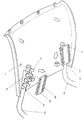
- This carrier shell 1 shows the carrier shell 1 of a backrest for seating.
- This carrier shell is made of polypropylene, for example. It is to be attached to the spars 2 of the stand frame of a chair.
- the carrier shell 1 has formations 3 with the shape of the spars 2.
- toothed strips 4 are attached to the carrier shell.
- locking slide 5 are provided. These locking slides 5, which are made of polypropylene, for example, are provided with openings 6 which correspond to the teeth 7 of the toothed strips 4.
- 1 shows how the latching slide 5 can be placed on the toothed strips 4 in the direction of the arrow shown.
- the locking slide 5 is placed on the toothed strips 4, of which only the teeth 7 can be seen in the picture.
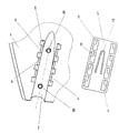
- the teeth 7 of the toothed strips 4 have lugs 8 which are horizontally directed outwards at the top.
- the openings 6 in the locking slides 5 have constrictions in their upper part, so that an opening 6 has an overall approximately L-shape.
- the openings 6 are dimensioned such that the lugs 8 of the teeth 7 of the toothed strips 4 can pass through the wide parts of the openings 6, but not at the constrictions 9.
- 3 pins 10 are attached to the carrier shell 1 in the formations. These pins 10 correspond to bores in the spars 2.
- a backrest The function of a backrest according to the invention is now as follows: For assembly, the carrier shell 1 with the formations 3 is placed on the spars 2. The pins 10 snap into bores in the spars 2 (not shown). Then the two locking slides 5 are guided with the wide parts of their openings 6 over the teeth 7 of the toothed strips 4. This is followed by a shift of the locking slide 5 in the direction of the arrow shown in the right-hand formation 3, so that the teeth 7 of the toothed strips 4 enter the constrictions 9 of the openings 6 and the lugs 8 lock the locking slide 5, as a result of which the entire carrier shell 1 is fixed to the spars 2.
- the carrier shell 1 is completed with a complementary shell, not shown, which then carries the back cushion, it is advantageous to provide recesses for the locking slide 5 in this cushion shell, in which the locking slide 5 are immovably fixed after the connection of the two shells.
- the locking slides 5 with tongues 11 as shown in FIG. 2, which have pins 12 at their ends: these pins 12 then slide over the bars 2 when the locking slides 5 are moved in a locking manner until they finally engage in the openings 13 of the spars 2 and secure the locking slides 5 against unintentional unlocking shifting.
- the openings 13 in the spars 2 can, moreover, be provided as standard, in order then to serve, if appropriate, for the fastening of a backrest by means of screws.
- the elements shown in FIG. 1, not provided with reference numbers, serve to connect the carrier shell 1 to a complementary cushion shell, as described in another, previously filed patent application by the same applicant with the title "component for the seat or the back of a piece of seating furniture" is.
Landscapes
- Chair Legs, Seat Parts, And Backrests (AREA)
- Chairs For Special Purposes, Such As Reclining Chairs (AREA)
- Chairs Characterized By Structure (AREA)
Description
Bei solchen Rückenlehnen ist es nicht nur wichtig, daß sie kostengünstig in großen Stückzahlen herzustellen sind, sondern sie müssen auch im Hinblick auf Transport, Lagerung, Montage und Demontage, Ästhetik und schließlich auch Entsorgbarkeit optimiert werden. Des weiteren sollen sie Variationen bei der Zusammenstellung der einzelnen Bauteile des Sitzmöbels im Sinne eines Baukastensystems ermöglichen.
Entweder weist die Rückenlehne zwei parallel verlaufende zylindrische Ausnehmungen auf, mittels derer die Lehne engsitzend auf die Holme aufgeschoben wird (siehe GB-A-1 438 638, welches Dokument eine Rückenlehne gemäß dem Oberbegriff des unabhängigen Anspruchs offenbart.)
Oder die Rückenlehne wird an die Holme angeschraubt.
Die erstgenannte Lösung hat insbesondere den Nachteil, daß die Ausnehmungen parallel verlaufen müssen, weil sonst kein stramm sitzendes Aufschieben der Lehne auf die Holme möglich ist. Des weiteren sind auch enge Passungen und festes Material erforderlich, damit die Lehne auch noch nach langem intensiven Gebrauch fest sitzt.
Die zweitgenannte Lösung hat insbesondere die Nachteile, daß zur Montage Werkzeug erforderlich ist, daß die sichtbaren Schrauben ästhetisch stören, und daß ein relativ voluminöser Aufbau der Lehne unvermeidbar ist, da unvermeidbar eine gewisse minimale Materialstärke für die Schraubengewinde erforderlich ist.
Die folgenden Druckschriften beschreiben den technologischen Hintergrund des einschlägigen technischen Gebietes:
DE-A-40 28 481_beschreibt einen Rückenlehnenträger, in dem ein die Rückenlehne tragender, auf und ab bewegbarer Holm mittels einer Keilvorrichtung in der gewünschten Höhe festgeklemmt werden kann.
DE-U-73 09 654.5_beschreibt eine besonders ausgestaltete Befestigungsplatte für die Sitzschale bei Stühlen. FR 989 302 beschreibt ebenfalls eine besonders gestaltete Konstruktion für die Rückenlehne eines Sitzmöbels.
Diese Aufgabe wird durch die Merkmale des Anspruchs 1 und der Unteransprüche gelöst.
Der Kern der Erfindung besteht darin, daß die erfindungsgemäße Rückenlehne beidseits von Zahnleisten flankierte Ausformungen aufweist, in welche die Enden der Träger-Holme eingelegt werden, und die eingelegten Holme dann mittels Rastschiebern verriegelt werden.
Dadurch wird es insbesondere möglich, die Holme in Richtungen laufen zu lassen, die vom ästhetischen oder technischen Design her erwünscht sind, und die Lehnen werkzeugfrei zu montieren und zu demontieren. Des weiteren ist ein flacher und kompakter Aufbau gegeben, und wegen völlig fehlender Metallteile ist auch eine Entsorgung vereinfacht. Da an den Holmen keine Änderungen notwendig sind, können auch anders konstruierte Lehnen montiert werden, sodaß auch die gewünschte Variationsmöglichkeit hinsichtlich der eingesetzten Bauteile gegeben ist.
- Fig.1
- eine perspektivische Ansicht einer Rückenlehne nach der Erfindung, und
- Fig.2
- eine Draufsicht auf eine Ausformung in der Trägerschale und einen Rastschieber.
Die Trägerschale 1 weist Ausformungen 3 mit der Form der Holme 2 auf. Beidseits dieser Ausformungen 3 sind an der Trägerschale 1 Zahnleisten 4 angebracht.
Des weiteren sind Rastschieber 5 vorgesehen. Diese Rastschieber 5, die zum Beispiel aus Polypropylen bestehen, sind mit Öffnungen 6 versehen, die mit den Zähnen 7 der Zahnleisten 4 korrespondieren.
An der linken Ausformung 3 in der Fig.1 ist gezeigt, wie der Rastschieber 5 in Richtung des gezeichneten Pfeils auf die Zahnleisten 4 aufgesetzt werden kann. An der rechten Ausformung 3 ist der Rastschieber 5 auf die Zahnleisten 4, von denen im Bild nur die Zähne 7 zu sehen sind, aufgesetzt. Wie in dem linken Teil der Fig.2 zu sehen ist, weisen die Zähne 7 der Zahnleisten 4 oben waagrecht nach außen gerichtete Nasen 8 auf. Im rechten Teil der Fig.2 sieht man, daß die Öffnungen 6 in den Rastschiebern 5 in ihrem oberen Teil Verengungen haben, sodaß eine Öffnung 6 insgesamt in etwa eine L-Form hat. Die Öffnungen 6 sind derart dimensioniert, daß die Nasen 8 der Zähne 7 der Zahnleisten 4 durch die breiten Teile der Öffnungen 6 hindurchtreten können, bei den Verengungen 9 jedoch nicht.
Aus Fig.2 ist auch ersichtlich, daß an der Trägerschale 1 in den Ausformungen 3 Zapfen 10 angebracht sind. Diese Zapfen 10 korrespondieren zu Bohrungen in den Holmen 2.
Die Funktion einer Rückenlehne nach der Erfindung ist nun wie folgt:
Zur Montage wird die Trägerschale 1 mit den Ausformungen 3 auf die Holme 2 aufgesetzt. Dabei rasten die Zapfen 10 in (nicht gezeigte) Bohrungen der Holme 2 ein. Sodann werden die beiden Rastschieber 5 mit den breiten Teilen ihrer Öffnungen 6 über die Zähne 7 der Zahnleisten 4 geführt.
Danach erfolgt eine Verschiebung der Rastschieber 5 in Richtung des bei der rechten Ausformung 3 gezeigten Pfeiles nach unten, sodaß die Zähne 7 der Zahnleisten 4 in die Verengungen 9 der Öffnungen 6 eintreten und die Nasen 8 den Rastschieber 5 verriegeln, wodurch dann die ganze Trägerschale 1 an den Holmen 2 fixiert ist.
Um die Rastschieber 5 gegen ein unbeabsichtigtes Entriegeln zu sichern, sind zwei Möglichkeiten vorgesehen:
Wenn die Trägerschale 1 mit einer komplementären, nicht gezeigten Schale abgeschlossen wird, welche dann das Rückenpolster trägt, so ist es vorteilhaft, in dieser Polsterschale Ausnehmungen für die Rastschieber 5 vorzusehen, in welchen nach der Verbindung der beiden Schalen die Rastschieber 5 unverschiebbar festliegen.
Es ist jedoch auch oder zusätzlich möglich, die Rastschieber 5 mit wie in Fig.2 gezeigten Zungen 11 zu versehen, die an ihrem Ende Zapfen 12 tragen: Diese Zapfen 12 gleiten dann beim verriegelnden Verschieben der Rastschieber 5 über die Holme 2, bis sie schließlich in die Öffnungen 13 der Holme 2 einrasten und die Rastschieber 5 gegen unbeabsichtigtes entriegelndes Verschieben sichern.
Die Öffnungen 13 in den Holmen 2 können übrigens serienmäßig vorgesehen werden, um dann gegebenenfalls für die Befestigung einer Lehne mittels Schrauben zu dienen.
Die in Fig.1 gezeigten, nicht mit Bezugszahlen versehenen Elemente dienen zur Verbindung der Trägerschale 1 mit einer komplementären Polsterschale, wie dies in einer anderen, früher eingereichten Patentanmeldung der gleichen Anmelderin mit dem Titel "Bauteil für den Sitz oder die Lehne eines Sitzmöbels" beschrieben ist.
- 1
- Trägerschale
- 2
- Holm
- 3
- Ausformung in der Trägerschale
- 4
- Zahnleisten beidseits der Ausformungen
- 5
- Rastschieber
- 6
- Öffnungen im Rastschieber
- 7
- Zähne der Zahnleiste
- 8
- Nasen an den Zähnen
- 9
- Verengungen der Öffnungen im Rastschieber
- 10
- Zapfen in den Ausformungen
- 11
- Zunge des Rastschiebers
- 12
- Zapfen der Zunge
- 13
- Öffnungen auf der Oberseite der Holme
Claims (4)
- Rückenlehne zur Befestigung an den rohrförmigen Holmen (2) eines Sitzmöbels, welche eine Trägerschale (1) umfaßt, die an den Holmen (2) befestigbar ist,
dadurch gekennzeichnet, daßdie Trägerschale (1) je eine Ausformung (3) für die Holme (2) aufweist, die beidseitig in Richtung der Holme (2) von Zahnleisten (4) flankiert sind, undein Rastschieber (5) vorgesehen ist, der den Zahnleisten (4) entsprechende Öffnungen (6) aufweist, wobeidie Zähne (7) der Zahnleisten (4) Nasen (8), und die Öffnungen (6) der Rastschieber (5) Verengungen (9) aufweisen, derartdaß die Nasen (8) in einer ersten Stellung des Rastschiebers (5) die Öffnungen (6) durchtreten können, in einer parallel zur ersten Stellung verschobenen Stellung jedoch den Rastschieber (5) verriegeln. - Rückenlehne nach Anspruch 1, dadurch gekennzeichnet, daß in den Ausformungen (3) Zapfen (10) vorgesehen sind, die in korrespondierende Öffnungen der Holme (2) einrastbar sind.
- Rückenlehne nach Anspruch 1, dadurch gekennzeichnet, daß eine mit der Trägerschale (1) lösbar verbindliche Lehnenschale vorgesehen ist, welche Ausnehmungen für die Aufnahme der Rastschieber (5) aufweist, derart, daß die Rastschieber (5) in ihrer Verriegelungsstellung unverschiebbar fixiert sind, wenn die Lehnenschale auf die Trägerschale (1) aufgesetzt ist.
- Rückenlehne nach Anspruch 1, dadurch gekennzeichnet, daß der Rastschieber (5) mit einer Zunge (11) versehen ist, die an ihrem Ende einen Zapfen (12) aufweist, der in eine korrespondierende Öffnung (13) des Holmes (2) einrastbar ist.
Applications Claiming Priority (2)
| Application Number | Priority Date | Filing Date | Title |
|---|---|---|---|
| DE19534699 | 1995-09-19 | ||
| DE19534699A DE19534699A1 (de) | 1995-09-19 | 1995-09-19 | Rückenlehne für Sitzmöbel |
Publications (2)
| Publication Number | Publication Date |
|---|---|
| EP0764413A1 EP0764413A1 (de) | 1997-03-26 |
| EP0764413B1 true EP0764413B1 (de) | 2001-01-24 |
Family
ID=7772556
Family Applications (1)
| Application Number | Title | Priority Date | Filing Date |
|---|---|---|---|
| EP96112638A Expired - Lifetime EP0764413B1 (de) | 1995-09-19 | 1996-08-05 | Rückenlehne für Sitzmöbel |
Country Status (4)
| Country | Link |
|---|---|
| EP (1) | EP0764413B1 (de) |
| AT (1) | ATE198822T1 (de) |
| DE (2) | DE19534699A1 (de) |
| ES (1) | ES2155554T3 (de) |
Families Citing this family (4)
| Publication number | Priority date | Publication date | Assignee | Title |
|---|---|---|---|---|
| GB9902433D0 (en) * | 1999-02-04 | 1999-03-24 | Walker Arthur T | Stadium etc. seating |
| FR2831781B1 (fr) * | 2001-11-02 | 2007-01-05 | Patrick Pagnon | Nouvelle structure de siege et son procede de fabrication |
| US7416251B2 (en) | 2005-06-10 | 2008-08-26 | Global Total Office | Chair |
| ATE504226T1 (de) * | 2005-12-23 | 2011-04-15 | Steelcase Sa | Querverriegelung eines rohres mit einer schale |
Family Cites Families (6)
| Publication number | Priority date | Publication date | Assignee | Title |
|---|---|---|---|---|
| DE7309654U (de) * | 1973-07-12 | Miwag Sitzmoebelfabrik Wagner M | Befestigungsplatte für die Sitzschale bei Stühlen | |
| FR989302A (fr) * | 1949-04-22 | 1951-09-07 | Art Et Tech | Réglette supports de dossiers suspendus et meuble classeur pour les dossiers comportant ces réglettes |
| FR1505526A (fr) * | 1966-11-02 | 1967-12-15 | Plaxico | Dispositif pour la fixation amovible du dessus d'un siège ou autre meuble, sur son piétement |
| GB1438638A (en) * | 1972-10-02 | 1976-06-09 | Remploy Ltd | Chairs |
| DE4028481A1 (de) * | 1990-09-07 | 1992-03-12 | Beer Gmbh Metallwarenfabrik | Rueckenlehnentraeger fuer sitzmoebel |
| ZA93308B (en) * | 1992-01-21 | 1994-05-23 | Bio Support Ind | Demountable backrest |
-
1995
- 1995-09-19 DE DE19534699A patent/DE19534699A1/de not_active Withdrawn
-
1996
- 1996-08-05 AT AT96112638T patent/ATE198822T1/de not_active IP Right Cessation
- 1996-08-05 ES ES96112638T patent/ES2155554T3/es not_active Expired - Lifetime
- 1996-08-05 EP EP96112638A patent/EP0764413B1/de not_active Expired - Lifetime
- 1996-08-05 DE DE59606368T patent/DE59606368D1/de not_active Expired - Fee Related
Also Published As
| Publication number | Publication date |
|---|---|
| DE19534699A1 (de) | 1997-03-20 |
| DE59606368D1 (de) | 2001-03-01 |
| ES2155554T3 (es) | 2001-05-16 |
| EP0764413A1 (de) | 1997-03-26 |
| ATE198822T1 (de) | 2001-02-15 |
Similar Documents
| Publication | Publication Date | Title |
|---|---|---|
| EP0664981A2 (de) | Untergestell für Tischplatten für Einzel- und Reihentische | |
| EP0435206B1 (de) | Stuhlkonstruktion zum Aufbau von Stuhlreihen | |
| EP2063735B1 (de) | Tisch, insbesondere schülertisch | |
| DE8018302U1 (de) | Fahrzeugsitz | |
| AT401851B (de) | Beschlag | |
| EP0764413A1 (de) | Rückenlehne für Sitzmöbel | |
| DE19504542A1 (de) | Stuhl | |
| DE69507925T2 (de) | Schaustand mit veränderlicher Länge | |
| DE69507794T2 (de) | Schaugestell für dokumente | |
| DE29802700U1 (de) | Ablagerost mit schmalem Lichtraumprofil | |
| DE19821898C1 (de) | Regalsystem | |
| EP1468634B1 (de) | Stapelbarer Reihenstuhl | |
| AT395097B (de) | Moebel mit einem schubkasten | |
| DE4428390A1 (de) | Tischuntergestellsystem zur Aufnahme und zum Befestigen einer Tischplatte | |
| DE69014054T2 (de) | Struktur zum Aufbau von Sitzreihen und Sitz. | |
| DE2620438C3 (de) | Mehrteiliges, kastenförmiges Möbelstück | |
| DE19920918C2 (de) | Toilettensitzerhöhung | |
| DE9110715U1 (de) | Regalgestell | |
| DE3715932C1 (en) | Table combination | |
| EP0413396A1 (de) | Haushaltgerät, z.B. Geschirrspülmaschine | |
| DE29516457U1 (de) | Regal | |
| EP1495698B1 (de) | Reihenverkettung für Mehrzweckstühle | |
| DE6937854U (de) | Sockel fuer moebel | |
| DE8708765U1 (de) | Einrichtung zum Verbinden der Einlegeböden zweier sich rechtwinklig zueinander erstreckender Regale | |
| EP0695524A1 (de) | Sitzanordnung mit wenigstens zwei Sitzteilen |
Legal Events
| Date | Code | Title | Description |
|---|---|---|---|
| PUAI | Public reference made under article 153(3) epc to a published international application that has entered the european phase |
Free format text: ORIGINAL CODE: 0009012 |
|
| AK | Designated contracting states |
Kind code of ref document: A1 Designated state(s): AT CH DE ES FR GB IT LI NL |
|
| 17P | Request for examination filed |
Effective date: 19970728 |
|
| GRAG | Despatch of communication of intention to grant |
Free format text: ORIGINAL CODE: EPIDOS AGRA |
|
| 17Q | First examination report despatched |
Effective date: 20000425 |
|
| GRAG | Despatch of communication of intention to grant |
Free format text: ORIGINAL CODE: EPIDOS AGRA |
|
| GRAH | Despatch of communication of intention to grant a patent |
Free format text: ORIGINAL CODE: EPIDOS IGRA |
|
| GRAH | Despatch of communication of intention to grant a patent |
Free format text: ORIGINAL CODE: EPIDOS IGRA |
|
| GRAA | (expected) grant |
Free format text: ORIGINAL CODE: 0009210 |
|
| AK | Designated contracting states |
Kind code of ref document: B1 Designated state(s): AT CH DE ES FR GB IT LI NL |
|
| REF | Corresponds to: |
Ref document number: 198822 Country of ref document: AT Date of ref document: 20010215 Kind code of ref document: T |
|
| REG | Reference to a national code |
Ref country code: CH Ref legal event code: EP |
|
| REF | Corresponds to: |
Ref document number: 59606368 Country of ref document: DE Date of ref document: 20010301 |
|
| ITF | It: translation for a ep patent filed | ||
| GBT | Gb: translation of ep patent filed (gb section 77(6)(a)/1977) |
Effective date: 20010403 |
|
| REG | Reference to a national code |
Ref country code: ES Ref legal event code: FG2A Ref document number: 2155554 Country of ref document: ES Kind code of ref document: T3 |
|
| ET | Fr: translation filed | ||
| PLBE | No opposition filed within time limit |
Free format text: ORIGINAL CODE: 0009261 |
|
| STAA | Information on the status of an ep patent application or granted ep patent |
Free format text: STATUS: NO OPPOSITION FILED WITHIN TIME LIMIT |
|
| REG | Reference to a national code |
Ref country code: GB Ref legal event code: IF02 |
|
| 26N | No opposition filed | ||
| PGFP | Annual fee paid to national office [announced via postgrant information from national office to epo] |
Ref country code: GB Payment date: 20040730 Year of fee payment: 9 |
|
| PGFP | Annual fee paid to national office [announced via postgrant information from national office to epo] |
Ref country code: DE Payment date: 20040805 Year of fee payment: 9 |
|
| PGFP | Annual fee paid to national office [announced via postgrant information from national office to epo] |
Ref country code: CH Payment date: 20040806 Year of fee payment: 9 |
|
| PGFP | Annual fee paid to national office [announced via postgrant information from national office to epo] |
Ref country code: FR Payment date: 20040809 Year of fee payment: 9 |
|
| PGFP | Annual fee paid to national office [announced via postgrant information from national office to epo] |
Ref country code: AT Payment date: 20040810 Year of fee payment: 9 |
|
| PGFP | Annual fee paid to national office [announced via postgrant information from national office to epo] |
Ref country code: NL Payment date: 20040818 Year of fee payment: 9 |
|
| PGFP | Annual fee paid to national office [announced via postgrant information from national office to epo] |
Ref country code: ES Payment date: 20040819 Year of fee payment: 9 |
|
| PG25 | Lapsed in a contracting state [announced via postgrant information from national office to epo] |
Ref country code: IT Free format text: LAPSE BECAUSE OF NON-PAYMENT OF DUE FEES;WARNING: LAPSES OF ITALIAN PATENTS WITH EFFECTIVE DATE BEFORE 2007 MAY HAVE OCCURRED AT ANY TIME BEFORE 2007. THE CORRECT EFFECTIVE DATE MAY BE DIFFERENT FROM THE ONE RECORDED. Effective date: 20050805 Ref country code: GB Free format text: LAPSE BECAUSE OF NON-PAYMENT OF DUE FEES Effective date: 20050805 Ref country code: AT Free format text: LAPSE BECAUSE OF NON-PAYMENT OF DUE FEES Effective date: 20050805 |
|
| PG25 | Lapsed in a contracting state [announced via postgrant information from national office to epo] |
Ref country code: ES Free format text: LAPSE BECAUSE OF NON-PAYMENT OF DUE FEES Effective date: 20050806 |
|
| PG25 | Lapsed in a contracting state [announced via postgrant information from national office to epo] |
Ref country code: LI Free format text: LAPSE BECAUSE OF NON-PAYMENT OF DUE FEES Effective date: 20050831 Ref country code: CH Free format text: LAPSE BECAUSE OF NON-PAYMENT OF DUE FEES Effective date: 20050831 |
|
| PG25 | Lapsed in a contracting state [announced via postgrant information from national office to epo] |
Ref country code: NL Free format text: LAPSE BECAUSE OF NON-PAYMENT OF DUE FEES Effective date: 20060301 Ref country code: DE Free format text: LAPSE BECAUSE OF NON-PAYMENT OF DUE FEES Effective date: 20060301 |
|
| REG | Reference to a national code |
Ref country code: CH Ref legal event code: PL |
|
| GBPC | Gb: european patent ceased through non-payment of renewal fee |
Effective date: 20050805 |
|
| PG25 | Lapsed in a contracting state [announced via postgrant information from national office to epo] |
Ref country code: FR Free format text: LAPSE BECAUSE OF NON-PAYMENT OF DUE FEES Effective date: 20060428 |
|
| NLV4 | Nl: lapsed or anulled due to non-payment of the annual fee |
Effective date: 20060301 |
|
| REG | Reference to a national code |
Ref country code: FR Ref legal event code: ST Effective date: 20060428 |
|
| REG | Reference to a national code |
Ref country code: ES Ref legal event code: FD2A Effective date: 20050806 |