EP0764103B1 - Vorrichtung zur verbindung von schienenfahrzeugen - Google Patents
Vorrichtung zur verbindung von schienenfahrzeugen Download PDFInfo
- Publication number
- EP0764103B1 EP0764103B1 EP96909125A EP96909125A EP0764103B1 EP 0764103 B1 EP0764103 B1 EP 0764103B1 EP 96909125 A EP96909125 A EP 96909125A EP 96909125 A EP96909125 A EP 96909125A EP 0764103 B1 EP0764103 B1 EP 0764103B1
- Authority
- EP
- European Patent Office
- Prior art keywords
- friction lining
- wagon
- friction
- thrust
- sliding
- Prior art date
- Legal status (The legal status is an assumption and is not a legal conclusion. Google has not performed a legal analysis and makes no representation as to the accuracy of the status listed.)
- Expired - Lifetime
Links
- 230000008878 coupling Effects 0.000 title 1
- 238000010168 coupling process Methods 0.000 title 1
- 238000005859 coupling reaction Methods 0.000 title 1
- 230000005764 inhibitory process Effects 0.000 claims description 7
- 230000002401 inhibitory effect Effects 0.000 claims description 5
- 239000000463 material Substances 0.000 claims description 2
- 241000237519 Bivalvia Species 0.000 claims 1
- 235000020639 clam Nutrition 0.000 claims 1
- 230000001419 dependent effect Effects 0.000 claims 1
- 230000003019 stabilising effect Effects 0.000 claims 1
- 230000006835 compression Effects 0.000 description 5
- 238000007906 compression Methods 0.000 description 5
- 230000036316 preload Effects 0.000 description 2
- 230000006735 deficit Effects 0.000 description 1
- 230000000694 effects Effects 0.000 description 1
- 238000009434 installation Methods 0.000 description 1
- 230000003993 interaction Effects 0.000 description 1
- 230000006641 stabilisation Effects 0.000 description 1
- 238000011105 stabilization Methods 0.000 description 1
- 230000000087 stabilizing effect Effects 0.000 description 1
- 239000000725 suspension Substances 0.000 description 1
Images


Classifications
-
- B—PERFORMING OPERATIONS; TRANSPORTING
- B62—LAND VEHICLES FOR TRAVELLING OTHERWISE THAN ON RAILS
- B62D—MOTOR VEHICLES; TRAILERS
- B62D47/00—Motor vehicles or trailers predominantly for carrying passengers
- B62D47/02—Motor vehicles or trailers predominantly for carrying passengers for large numbers of passengers, e.g. omnibus
- B62D47/025—Motor vehicles or trailers predominantly for carrying passengers for large numbers of passengers, e.g. omnibus articulated buses with interconnecting passageway, e.g. bellows
-
- B—PERFORMING OPERATIONS; TRANSPORTING
- B61—RAILWAYS
- B61D—BODY DETAILS OR KINDS OF RAILWAY VEHICLES
- B61D17/00—Construction details of vehicle bodies
- B61D17/04—Construction details of vehicle bodies with bodies of metal; with composite, e.g. metal and wood body structures
- B61D17/20—Communication passages between coaches; Adaptation of coach ends therefor
-
- B—PERFORMING OPERATIONS; TRANSPORTING
- B61—RAILWAYS
- B61D—BODY DETAILS OR KINDS OF RAILWAY VEHICLES
- B61D3/00—Wagons or vans
- B61D3/10—Articulated vehicles
Definitions
- the invention relates to a device for connecting rail vehicles according to the preamble of claim 1, which are formed from several interconnected car parts, with one Swivel with swivel.
- Such a device for a multi-unit rail vehicle is known from EP 0 340 760 B1 known, the interconnected car parts each have a common Have articulated connection.
- the known device is for rail vehicles provided with a particularly low carriage floor, so that there is little space is available for such a swivel.
- the known device is therefore as closed slewing ring formed, each with an inner ring and an outer ring provided, rigid and torsionally rigid with the one car part and via a joint is connected to the other part of the car with a horizontal axis of rotation.
- rail vehicles show themselves in general and in the known multi-unit vehicle in particular that the individual car parts when driving through are excited by tracks to vibrations, which inevitably leads to unwanted Movements of the vehicle.
- movement around the vertical axis also called lurching, has a very negative effect on the running behavior of the vehicle out.
- the invention is based on the object to create a device of the type mentioned, the swaying of each other connected carriage parts prevented.
- the running properties should of the vehicle when passing through the arch.
- the device should work independently of the zipper.
- the device is advantageous arranged at least in regions on the circumference of the slewing ring, wherein the sliding bodies connect concentrically to the slewing ring on the outside.
- a preferred embodiment of the invention provides that the sliding body of a Sliding plate on the one hand and at least one friction lining on the other hand are formed.
- the sliding plate is firmly connected to one part of the carriage, while the friction lining is connected to the other part of the car.
- Friction lining divided into several individual linings, which are guided in so-called lining holders and are kept.
- the Pressure springs the friction linings against the sliding plate, creating the contact force between the sliding plate on the one hand and the friction lining on the other hand reinforced and the desired Anti-rotation can be increased can.
- the springs engage in so-called spring pockets, which on the associated Car part are arranged radially to the pivot point and one as Apply pressure on the pressure plate designated surface of the friction lining vertically.
- the Pressure plate is used here, which from the bias applied by the springs resulting contact force as evenly as possible on the contact surface between to transfer the friction lining and the sliding plate on the other part of the car.
- shims can be provided be used to balance between the springs and to bias the springs Clamping elements, preferably screw bolts, are inserted.
- a so-called segment sheet can also be used be provided, which is inserted between the pressure plate and the pad holder and serves to elasticize the loss of thickness of the friction lining due to wear adjust so that this also ensures an optimal contact pressure on the friction lining is applied.
- a frictional connection takes place through the device for the rotation inhibition of the parts of the car that work independently of frictional wear. This can cause the lurching movement of the individual car bodies prevented and a stabilization of the whole Vehicle movement can be achieved. That by the device according to the invention friction torque generated to inhibit rotation is only from the coefficient of friction used Material pairing and the effective contact pressure between the friction lining on the one hand and the sliding plate on the other hand. Only with arches it by the size of the relative movement of those connected in the swivel joint Car parts overcome.
- EP-A-0 032 079 describes a device for connecting Bus vehicles with a joint that is between a main car and a Trailer is arranged. Sliding bodies are provided in the area of the joint, which are spaced apart. By applying a hydraulic If necessary, the sliding bodies can be pressed against one another by friction be so that a rotation inhibition in the joint is effected.
- Fig. 1 is an arrangement of two carriage parts 1, 2 in a schematic representation Top view shown, which can be pivoted about a pivot point 5 by means of a swivel joint 3 are interconnected.
- a device for Anti-rotation 4 according to the invention shown as a semicircular wide line.
- This representation shows that the device according to the invention Rotation inhibition 4 concentric with the rotating ring of the swivel, not shown in detail 3 is arranged with the fulcrum 5, the device for anti-rotation 4 according to of the invention in the example shown here only covers a range of approximately 120 °.
- the semicircular arrow 6 is a rotational movement of the car part 1 is displayed around its vertical axis, which leads to instabilities in straight running and is commonly referred to as lurching.
- Another semicircular arrow 7 denotes the counter-torque provided according to the invention for compensating the roll 6, that has a stabilizing effect and the rotary movement 6 regardless of their Counteracts size and speed.
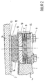
- FIG. 2 is a schematic longitudinal section through a device according to the invention 4 shown to inhibit rotation with a first carriage part 1 and a second carriage part 2.
- the first carriage part 1 is connected to the second carriage part 2 via a swivel joint 3 articulated coupled, in particular in Fig. 2 the radial distance from here only indicated pivot point 5 of the hinge 3 arranged rotation inhibiting device 4 is shown with its details, such as the joint parts 3a, 3b, the spring pockets 7, the compression spring 8, which is designed here as a plate spring package, and tensioning screws 9 and a pressure plate 10.
- FIG. 3 shows a partial bottom view of the swivel joint 3, wherein the anti-rotation device 4 according to the invention is shown in partial section is. From this it can be seen that several compression springs 8 are provided, each in engage a friction lining element 12, which in turn abut the slide plate 13. Further the contour of the segment plate 11 can be seen with the incisions.
- the device for anti-rotation 4 is as follows to emphasize. On the carriage part 1 are radially to the pivot point 5, the joint part 3 a spring pockets for the vertical installation of springs 8 provided. Any of these Springs is with screws 9 on the hinge part 3 a of the carriage part 1 in these spring pockets 7 attached. The springs act vertically on pressure plates 10.
- friction linings 12 are fastened in the lining holder 14.
- the friction linings 12 rest under a sliding plate 13 which is fixed to the joint part 3 b of the carriage part 2 is attached, wherein the hinge part 3 b is also firmly attached to the Carriage part 2 is arranged and the joint parts 3 a and 3 b of the joint 3 in their vertical distance are fixed against each other. Since the pressure plates 10 and the segment sheet 11 are not connected to each other, is a constant, flat pressing the Guaranteed friction linings 12 on the sliding plate 13.
- the slotted segment plate 11 can adapt elastically to the friction lining wear. By ensuring the freedom from play between the friction linings 12 and Sliding plate 13, is achieved with the slightest rotary movement between pads and Slide plate immediately the maximum value of the realizable friction torque.
- the one on the joint part 3 b of the carriage part 2 attached slide plate 13 passes over during a rotary movement the carriage parts 1, 2, the friction linings 12, which are caused by the spring forces via pressure plates 10 and segment plate 11 are pressed against the slide plate 13.
- the resulting friction torque is due to a variable spring preload during assembly adjustable.
- the springs 8 are underlaid with shims 15. The bringing in the shims continue to compensate for wear and tear of the friction linings changed spring force.
Landscapes
- Engineering & Computer Science (AREA)
- Mechanical Engineering (AREA)
- Transportation (AREA)
- Chemical & Material Sciences (AREA)
- Combustion & Propulsion (AREA)
- Life Sciences & Earth Sciences (AREA)
- Wood Science & Technology (AREA)
- Platform Screen Doors And Railroad Systems (AREA)
- Braking Arrangements (AREA)
- Mechanical Operated Clutches (AREA)
- Machines For Laying And Maintaining Railways (AREA)
- Electric Propulsion And Braking For Vehicles (AREA)
- Vibration Dampers (AREA)
- Train Traffic Observation, Control, And Security (AREA)
- Control Of Vehicles With Linear Motors And Vehicles That Are Magnetically Levitated (AREA)
- Vehicle Body Suspensions (AREA)
- Joints Allowing Movement (AREA)
Description
- Fig. 1
- zwei miteinander verbundene Wagenteile in schematischer Darstellung in Draufsicht,
- Fig. 2
- eine Vorrichtung zur Drehhemmung im Längsschnitt,
- Fig. 3
- einen Teil eines Drehgelenks im Teilschnitt in Ansicht von unten.
Claims (15)
- Vorrichtung zur Verbindung von Schienenfahrzeugen, welche aus mehreren miteinander mit einem einen Drehkranz aufweisenden Drehgelenk (3) verbundenen ersten und zweiten Wagenteilen (1, 2) gebildet sind, wobei im Bereich des Drehgelenks (3) zwischen je zwei Wagenteilen (1, 2) eine Vorrichtung (4) zur Drehhemmung vorgesehen ist, die von zumindest zwei am Umfang des Drehkranzes des Drehgelenks (3) angeordneten Gleitkörpern (12, 13) gebildet ist,
dadurch gekennzeichnet, daß
wenigstens eine Druckfeder vorgesehen ist, so daß die Gleitkörper (12, 13) spielfrei und unter Vorspannung aneinander liegen sowie reibschlüssig miteinander zusammenarbeiten, wobei die Gleitkörper (12, 13) jeweils an einem der beiden im Drehgelenk (3) verbundenen Wagenteile (1, 2) befestigbar sind. - Vorrichtung nach Anspruch 1, dadurch gekennzeichnet, daß die Vorrichtung (4) zur Drehhemmung zumindest bereichsweise am Umfang des Drehkranzes angeordnet ist, und daß sich die Gleitkörper (12, 13) konzentrisch zum Drehkranz an diesen anschließen.
- Vorrichtung nach Anspruch 1 oder 2, dadurch gekennzeichnet, daß die Gleitkörper (12, 13) aus einer Gleitplatte (13) einerseits und wenigstens einem Reibbelag (12) andererseits gebildet sind.
- Vorrichtung nach Anspruch 3, dadurch gekennzeichnet, daß die Gleitplatte (13) fest mit dem einen Wagenteil (2) verbunden ist, während der Reibbelag (12) mit dem anderen Wagenteil (1) verbunden ist.
- Vorrichtung nach Anspruch 3 oder 4, dadurch gekennzeichnet, daß der Reibbelag in mehrere Einzelbeläge aufgeteilt ist, die in sogenannten Belaghaltern (14) geführt und gehalten sind.
- Vorrichtung nach einem der Ansprüche 3 bis 5, dadurch gekennzeichnet, daß die wenigstens eine Druckfeder (8) die Kontaktkraft zwischen der Gleitplatte (13) einerseits und dem Reibbelag (12) andererseits verstärkt.
- Vorrichtung nach einem der Ansprüche 3 bis 6, dadurch gekennzeichnet, daß die wenigstens eine Druckfeder (8) den Reibbelag (12) gegen die Gleitplatte (13) beaufschlagt und hierdurch die angestrebte Drehhemmung vergrößert.
- Vorrichtung nach einem der Ansprüche 3 bis 7, dadurch gekennzeichnet, daß an dem zugehörigen Wagenteil (1) radial zu einem Gelenkdrehpunkt (5) sogenannte Federtaschen (7) angeordnet sind, in welche die Druckfedern (8) eingreifen und eine als Druckplatte (10) bezeichnete Unterlage des Reibbelags (12) senkrecht beaufschlagen.
- Vorrichtung nach Anspruch 8, dadurch gekennzeichnet, daß die Druckplatte (10) dazu dient, die aus der von den Druckfedern (8) aufgebrachten Vorspannung herrührende Anpreßkraft möglichst gleichmäßig auf die Kontaktfläche zwischen dem Reibbelag (12) und der Gleitplatte (13) am anderen Wagenteil (2) zu übertragen.
- Vorrichtung nach einem der Ansprüche 3 bis 9, dadurch gekennzeichnet, daß zur Kompensation einer verschleißbedingten Abnahme der Dicke der Reibbeläge (12) und, damit einhergehend, einer Abnahme der Anpreßkraft Paßscheiben (15) vorgesehen sind, die zum Ausgleich zwischen die Druckfedern (8) und die zum Vorspannen der Druckfedern (8) dienenden Spannelemente (9), vorzugsweise Schraubenbolzen, eingefügt werden.
- Vorrichtung nach einen der Ansprüche 8 bis 10, dadurch gekennzeichnet, daß ein Segmentblech (11) zwischen der Druckplatte (10) und dem Belaghalter (14) eingefügt ist.
- Vorrichtung nach Anspruch 11, dadurch gekennzeichnet, daß das Segmentblech (11) dazu dient, sich elastisch dem Verlust an Dicke des Reibbelags (12) infolge Verschleiß anzupassen und daß so der Anpreßdruck auf den Reibbelag (12) optimal aufgebracht ist.
- Vorrichtung nach einem der vorherigen Ansprüche, dadurch gekennzeichnet, daß die Vorrichtung (4) zur Drehhemmung eine vom Reibverschleiß unabhängige reibkraftschlüssige Verbindung der Wagenteil (1, 2) bildet, welche die Schlingerbewegung der einzelnen Wagenkästen (1, 2) verhindert und zu einer Stabilisierung der gesamten Fahrzeugbewegung führt.
- Vorrichtung nach einem der Ansprüche 3 bis 13, dadurch gekennzeichnet, daß das durch die Vorrichtung (4) zur Drehhemmung erzeugte Reibmoment vom Reibwert der verwendeten Werkstoffpaarung sowie von der wirkenden Anpreßkraft zwischen dem Reibbelag (12) einerseits und der Gleitplatte (13) andererseits abhängig ist.
- Vorrichtung nach einem der vorherigen Ansprüche, dadurch gekennzeichnet, daß nur bei Bogenfährten die Größe der Relativbewegung der im Drehgelenk miteinander verbundenen Wagenteile (1, 2) die Drehhemmung übersteigt.
Applications Claiming Priority (3)
| Application Number | Priority Date | Filing Date | Title |
|---|---|---|---|
| DE19512630 | 1995-04-05 | ||
| DE19512630A DE19512630A1 (de) | 1995-04-05 | 1995-04-05 | Vorrichtung zur Verbindung von Schienenfahrzeugen |
| PCT/EP1996/001313 WO1996031383A1 (de) | 1995-04-05 | 1996-03-26 | Vorrichtung zur verbindung von schienenfahrzeugen |
Publications (2)
| Publication Number | Publication Date |
|---|---|
| EP0764103A1 EP0764103A1 (de) | 1997-03-26 |
| EP0764103B1 true EP0764103B1 (de) | 1999-09-29 |
Family
ID=7758780
Family Applications (1)
| Application Number | Title | Priority Date | Filing Date |
|---|---|---|---|
| EP96909125A Expired - Lifetime EP0764103B1 (de) | 1995-04-05 | 1996-03-26 | Vorrichtung zur verbindung von schienenfahrzeugen |
Country Status (10)
| Country | Link |
|---|---|
| US (1) | US5730062A (de) |
| EP (1) | EP0764103B1 (de) |
| AT (1) | ATE185120T1 (de) |
| AU (1) | AU695544B2 (de) |
| BR (1) | BR9606296A (de) |
| CA (1) | CA2192060A1 (de) |
| DE (2) | DE19512630A1 (de) |
| HU (1) | HU218889B (de) |
| PL (1) | PL180068B1 (de) |
| WO (1) | WO1996031383A1 (de) |
Cited By (1)
| Publication number | Priority date | Publication date | Assignee | Title |
|---|---|---|---|---|
| DE102005016713A1 (de) * | 2005-04-11 | 2006-10-12 | Bombardier Transportation Gmbh | Mehrgliedriges Fahrzeug |
Family Cites Families (17)
| Publication number | Priority date | Publication date | Assignee | Title |
|---|---|---|---|---|
| BE412544A (de) * | 1934-12-31 | |||
| NL241522A (de) * | 1958-07-24 | |||
| DE1233902B (de) * | 1959-12-08 | 1967-02-09 | Waggon Und Maschinenfabriken G | Schienengelenkwagen |
| DE1603263A1 (de) * | 1966-08-09 | 1971-02-25 | Ernst Max | Als dreiachsiger Autotransporter ausgebildetes Spielfahrzeug,insbesondere Eisenbahnspielfahrzeug |
| FR2398651A1 (fr) * | 1977-07-25 | 1979-02-23 | Venissieux Atel | Perfectionnement aux wagons articules |
| DE2842211A1 (de) * | 1978-09-28 | 1980-04-10 | Waggon Union Gmbh | Drehhemmung fuer einzel- und doppelachslaufwerke von schienenfahrzeugen |
| FR2473002A1 (fr) * | 1980-01-07 | 1981-07-10 | Heuliez Sa Louis | Vehicule articule, notamment autobus articule |
| SU1504137A1 (ru) * | 1988-01-07 | 1989-08-30 | Днепропетровский горный институт им.Артема | Сочлененное рельсовое транспортное средство |
| DE3815540A1 (de) * | 1988-05-06 | 1989-11-16 | Waggon Union Gmbh | Gelenkverbindung |
| FR2631917B1 (fr) * | 1988-05-24 | 1990-08-10 | Alsthom | Articulation d'accouplement de deux vehicules ferroviaires |
| US4924779A (en) * | 1989-02-21 | 1990-05-15 | Thrall Car Manufacturing Company | Long-travel side bearing for an articulated railroad car |
| FR2655602B1 (fr) * | 1989-12-08 | 1992-03-13 | Rks Sa | Dispositif de couronne d'orientation, notamment pour vehicules ferroviaires. |
| US5271678A (en) * | 1989-12-29 | 1993-12-21 | Caoutchouc Manufacture Et Plastiques S.A. | Elastic bearing |
| US5207161A (en) * | 1992-07-24 | 1993-05-04 | Gunderson, Inc. | Side bearing arrangement for multi-unit railroad cars with different side bearings on adjacent car ends sharing a common truck |
| DE4305614A1 (de) * | 1993-02-24 | 1994-08-25 | Linke Hofmann Busch | Gelenkverbindung zum gelenkigen Verbinden von Fahrzeugteilen eines mehrgliedrigen Schienenfahrzeugs |
| FR2716149B1 (fr) * | 1994-02-15 | 1996-03-29 | Gec Alsthom Transport Sa | Articulation d'accouplement et procédé d'absorption d'énergie entre deux véhicules ferroviaires. |
| DE9420646U1 (de) * | 1994-12-23 | 1995-02-16 | Itw-Ateco Gmbh, 22844 Norderstedt | Rotationsdämpfer |
-
1995
- 1995-04-05 DE DE19512630A patent/DE19512630A1/de not_active Ceased
-
1996
- 1996-03-26 DE DE59603212T patent/DE59603212D1/de not_active Expired - Lifetime
- 1996-03-26 CA CA002192060A patent/CA2192060A1/en not_active Abandoned
- 1996-03-26 WO PCT/EP1996/001313 patent/WO1996031383A1/de not_active Ceased
- 1996-03-26 AT AT96909125T patent/ATE185120T1/de active
- 1996-03-26 AU AU52739/96A patent/AU695544B2/en not_active Ceased
- 1996-03-26 BR BR9606296A patent/BR9606296A/pt not_active IP Right Cessation
- 1996-03-26 PL PL96317461A patent/PL180068B1/pl not_active IP Right Cessation
- 1996-03-26 HU HU9603222A patent/HU218889B/hu not_active IP Right Cessation
- 1996-03-26 EP EP96909125A patent/EP0764103B1/de not_active Expired - Lifetime
- 1996-12-05 US US08/760,821 patent/US5730062A/en not_active Expired - Fee Related
Cited By (2)
| Publication number | Priority date | Publication date | Assignee | Title |
|---|---|---|---|---|
| DE102005016713A1 (de) * | 2005-04-11 | 2006-10-12 | Bombardier Transportation Gmbh | Mehrgliedriges Fahrzeug |
| EP1712443A1 (de) | 2005-04-11 | 2006-10-18 | Bombardier Transportation GmbH | Mehrgliedriges Gelenkfahrzeug, insbesondere Schienenfahrzeug. |
Also Published As
| Publication number | Publication date |
|---|---|
| AU695544B2 (en) | 1998-08-13 |
| US5730062A (en) | 1998-03-24 |
| PL317461A1 (en) | 1997-04-14 |
| PL180068B1 (en) | 2000-12-29 |
| AU5273996A (en) | 1996-10-23 |
| DE19512630A1 (de) | 1996-10-10 |
| CA2192060A1 (en) | 1996-10-10 |
| EP0764103A1 (de) | 1997-03-26 |
| ATE185120T1 (de) | 1999-10-15 |
| HUP9603222A3 (en) | 2000-06-28 |
| HU218889B (hu) | 2000-12-28 |
| WO1996031383A1 (de) | 1996-10-10 |
| DE59603212D1 (de) | 1999-11-04 |
| HUP9603222A2 (en) | 1997-05-28 |
| BR9606296A (pt) | 1997-09-16 |
Similar Documents
| Publication | Publication Date | Title |
|---|---|---|
| EP1178893B1 (de) | Stabilisator für ein kraftfahrzeug | |
| EP2617622B1 (de) | Vorrichtung zum vertikalen Abstützen einer Kupplungsstange | |
| DE69924942T2 (de) | Blattfedergelenklager und Anordnung mit verstellbarem Führungselement | |
| DE3017307C2 (de) | Führung für die Tragplatten von Bremsbelägen einer Teilbelagscheibenbremse | |
| DE3323995C2 (de) | ||
| EP1027247B1 (de) | Zahnstangen-lenkgetriebe | |
| DE3218070C2 (de) | Vorrichtung für einen Straßen-Gelenkzug zur Beeinflussung des Knickwinkels mittels Reibungsbremsen | |
| DE69310779T2 (de) | Hinterradlenkeinrichtung | |
| WO1994023218A1 (de) | Kugelgelenk | |
| DE2902188C2 (de) | ||
| DE2313575C3 (de) | Hydrostatische Axialkolbenmaschine | |
| EP0248996B1 (de) | Verbundachsaggregat | |
| DE69132360T2 (de) | Bremsbackenhalterung für scheibenbremsenaggregat | |
| DE2003028B2 (de) | Teilbelagscheibenbremse | |
| DE2355954A1 (de) | Achsanordnung fuer einzelradaufhaengung | |
| DE29821113U1 (de) | Bremsbelag | |
| DE2110072C3 (de) | Achsführung an einem Drehgestell für Schienenfahrzeuge, insbesondere für Güterwagen | |
| DE19512630A1 (de) | Vorrichtung zur Verbindung von Schienenfahrzeugen | |
| EP3374655B1 (de) | Scheibenbremse und bremsbelagsatz | |
| DE29509484U1 (de) | Teilbelagscheibenbremse | |
| DE2842211A1 (de) | Drehhemmung fuer einzel- und doppelachslaufwerke von schienenfahrzeugen | |
| DE4343737B4 (de) | Scheibenbremse | |
| DE4205667C2 (de) | Elastische Gelenkanordnung für Gelenkhebel von Gelenkhebelkupplungen | |
| DE1505861A1 (de) | Gleiskettenglied mit abgedichteter Bolzenlagerung | |
| DE3211078A1 (de) | Schwimmsattelbremse, insbesondere fuer kraftfahrzeuge |
Legal Events
| Date | Code | Title | Description |
|---|---|---|---|
| PUAI | Public reference made under article 153(3) epc to a published international application that has entered the european phase |
Free format text: ORIGINAL CODE: 0009012 |
|
| 17P | Request for examination filed |
Effective date: 19961031 |
|
| AK | Designated contracting states |
Kind code of ref document: A1 Designated state(s): AT CH DE FI FR IT LI SE |
|
| RAP1 | Party data changed (applicant data changed or rights of an application transferred) |
Owner name: ABB DAIMLER-BENZ TRANSPORTATION (TECHNOLOGY) GMBH |
|
| 17Q | First examination report despatched |
Effective date: 19980803 |
|
| GRAG | Despatch of communication of intention to grant |
Free format text: ORIGINAL CODE: EPIDOS AGRA |
|
| GRAG | Despatch of communication of intention to grant |
Free format text: ORIGINAL CODE: EPIDOS AGRA |
|
| GRAH | Despatch of communication of intention to grant a patent |
Free format text: ORIGINAL CODE: EPIDOS IGRA |
|
| GRAH | Despatch of communication of intention to grant a patent |
Free format text: ORIGINAL CODE: EPIDOS IGRA |
|
| GRAA | (expected) grant |
Free format text: ORIGINAL CODE: 0009210 |
|
| AK | Designated contracting states |
Kind code of ref document: B1 Designated state(s): AT CH DE FI FR IT LI SE |
|
| REF | Corresponds to: |
Ref document number: 185120 Country of ref document: AT Date of ref document: 19991015 Kind code of ref document: T |
|
| REG | Reference to a national code |
Ref country code: CH Ref legal event code: EP |
|
| REF | Corresponds to: |
Ref document number: 59603212 Country of ref document: DE Date of ref document: 19991104 |
|
| ET | Fr: translation filed | ||
| REG | Reference to a national code |
Ref country code: CH Ref legal event code: PFA Free format text: ABB DAIMLER-BENZ TRANSPORTATION (TECHNOLOGY) GMBH TRANSFER- DAIMLERCHRYSLER AG |
|
| PLBE | No opposition filed within time limit |
Free format text: ORIGINAL CODE: 0009261 |
|
| STAA | Information on the status of an ep patent application or granted ep patent |
Free format text: STATUS: NO OPPOSITION FILED WITHIN TIME LIMIT |
|
| REG | Reference to a national code |
Ref country code: CH Ref legal event code: NV Representative=s name: DIPL.-ING. ETH H. R. WERFFELI PATENTANWALT |
|
| 26N | No opposition filed | ||
| REG | Reference to a national code |
Ref country code: FR Ref legal event code: TP Ref country code: FR Ref legal event code: CD |
|
| PGFP | Annual fee paid to national office [announced via postgrant information from national office to epo] |
Ref country code: SE Payment date: 20090312 Year of fee payment: 14 |
|
| EUG | Se: european patent has lapsed | ||
| PG25 | Lapsed in a contracting state [announced via postgrant information from national office to epo] |
Ref country code: SE Free format text: LAPSE BECAUSE OF NON-PAYMENT OF DUE FEES Effective date: 20100327 |
|
| PGFP | Annual fee paid to national office [announced via postgrant information from national office to epo] |
Ref country code: IT Payment date: 20120329 Year of fee payment: 17 |
|
| PGFP | Annual fee paid to national office [announced via postgrant information from national office to epo] |
Ref country code: FR Payment date: 20130408 Year of fee payment: 18 Ref country code: FI Payment date: 20130313 Year of fee payment: 18 |
|
| PGFP | Annual fee paid to national office [announced via postgrant information from national office to epo] |
Ref country code: AT Payment date: 20130313 Year of fee payment: 18 |
|
| PGFP | Annual fee paid to national office [announced via postgrant information from national office to epo] |
Ref country code: DE Payment date: 20140319 Year of fee payment: 19 |
|
| REG | Reference to a national code |
Ref country code: DE Ref legal event code: R082 Ref document number: 59603212 Country of ref document: DE Representative=s name: MAI, OPPERMANN & PARTNER I. L., DE |
|
| PG25 | Lapsed in a contracting state [announced via postgrant information from national office to epo] |
Ref country code: FI Free format text: LAPSE BECAUSE OF NON-PAYMENT OF DUE FEES Effective date: 20140326 |
|
| REG | Reference to a national code |
Ref country code: AT Ref legal event code: MM01 Ref document number: 185120 Country of ref document: AT Kind code of ref document: T Effective date: 20140326 |
|
| REG | Reference to a national code |
Ref country code: FR Ref legal event code: ST Effective date: 20141128 |
|
| PG25 | Lapsed in a contracting state [announced via postgrant information from national office to epo] |
Ref country code: FR Free format text: LAPSE BECAUSE OF NON-PAYMENT OF DUE FEES Effective date: 20140331 |
|
| PG25 | Lapsed in a contracting state [announced via postgrant information from national office to epo] |
Ref country code: AT Free format text: LAPSE BECAUSE OF NON-PAYMENT OF DUE FEES Effective date: 20140326 |
|
| PG25 | Lapsed in a contracting state [announced via postgrant information from national office to epo] |
Ref country code: IT Free format text: LAPSE BECAUSE OF NON-PAYMENT OF DUE FEES Effective date: 20140326 |
|
| PGFP | Annual fee paid to national office [announced via postgrant information from national office to epo] |
Ref country code: CH Payment date: 20150319 Year of fee payment: 20 |
|
| REG | Reference to a national code |
Ref country code: DE Ref legal event code: R119 Ref document number: 59603212 Country of ref document: DE |
|
| PG25 | Lapsed in a contracting state [announced via postgrant information from national office to epo] |
Ref country code: DE Free format text: LAPSE BECAUSE OF NON-PAYMENT OF DUE FEES Effective date: 20151001 |
|
| REG | Reference to a national code |
Ref country code: CH Ref legal event code: PL |