EP0763707A1 - Sealing device mounted between the enveloppe and the base of a cargo projectile - Google Patents
Sealing device mounted between the enveloppe and the base of a cargo projectile Download PDFInfo
- Publication number
- EP0763707A1 EP0763707A1 EP96401939A EP96401939A EP0763707A1 EP 0763707 A1 EP0763707 A1 EP 0763707A1 EP 96401939 A EP96401939 A EP 96401939A EP 96401939 A EP96401939 A EP 96401939A EP 0763707 A1 EP0763707 A1 EP 0763707A1
- Authority
- EP
- European Patent Office
- Prior art keywords
- sealing device
- base
- shell
- ring
- annular
- Prior art date
- Legal status (The legal status is an assumption and is not a legal conclusion. Google has not performed a legal analysis and makes no representation as to the accuracy of the status listed.)
- Ceased
Links
Images

Classifications
-
- F—MECHANICAL ENGINEERING; LIGHTING; HEATING; WEAPONS; BLASTING
- F42—AMMUNITION; BLASTING
- F42B—EXPLOSIVE CHARGES, e.g. FOR BLASTING, FIREWORKS, AMMUNITION
- F42B30/00—Projectiles or missiles, not otherwise provided for, characterised by the ammunition class or type, e.g. by the launching apparatus or weapon used
- F42B30/003—Closures or baseplates therefor
Definitions
- the mechanical connection between the casing and the base is made either by a thread, or by a tight fitting with retaining pins, this mechanical connection being associated with a sealing device.
- the base is connected to the shell of the shell by means of a mechanical connection intended to break at the time of the unloading of the shell, said ring placed in compression after assembly ensuring the tightness of the mechanical connection as long as the base is not separated from the envelope.
- the sealing device 6 consists of a ring 15 comprising a metallic annular body 16.
- the two annular end faces 18 of the metallic body 16 include projecting anchoring means 20.
- These anchoring means 20 are for example constituted by two ribs 22, annular and concentric, having substantially the same height.
- each rib 22 has a generally triangular shape.
- These two ribs 22 define between them an annular central groove 24 with, on either side of the ribs 22, two annular lateral half-grooves 26.
- the ring 15 extends over an axial length of 1 'order of 4 mm, and each rib has a height of about 0.5 mm.
- the two annular end faces 18 of the metal body 16 of the ring 15 are each covered with a layer of elastomer 28 having a thickness equal to or greater than the height of the ribs 22.
- the mechanical connection 5 between the base 3 and the casing 2 is thus protected by the ring 15 against aggression from external agents during the storage, logistics and maintenance phases.
Abstract
Description
L'invention concerne un dispositif d'étanchéité monté entre l'enveloppe et le culot d'un obus cargo, ce dispositif étant notamment utilisé pour un obus cargo à paroi mince.The invention relates to a sealing device mounted between the casing and the base of a cargo shell, this device being used in particular for a thin-walled cargo shell.
D'une manière générale, une munition cargo tirée par le canon d'une artillerie de campagne est constituée d'un obus de gros calibre renfermant la charge utile qui est libérée en un point de la trajectoire de l'obus après le lancement de ce dernier. La charge utile peut être une charge éclairante ou être constituée d'un empilement de plusieurs sous-munitions, par exemple.Generally, a cargo ammunition fired by the cannon of a field artillery consists of a large caliber shell containing the payload which is released at a point in the trajectory of the shell after the launch of this latest. The payload can be an illuminating load or consist of a stack of several submunitions, for example.
Une munition cargo de ce type est notamment décrite dans le document FR-A-2 363 077 et comprend un obus formé d'une enveloppe fermée à l'avant par une ogive et à l'arrière par un culot qui est relié à l'enveloppe au moyen d'une liaison mécanique destinée à se rompre au moment du dépotage. Le système de dépotage qui permet l'éjection de la charge utile comprend une composition pyrotechnique génératrice de gaz qui est montée dans l'ogive, et une fusée chronométrique pour initier la composition pyrotechnique. Après initiation de cette composition pyrotechnique, la pression des gaz résultants est appliquée sur la charge utile par l'intermédiaire d'un piston jusqu'à provoquer la rupture de la liaison mécanique entre le culot et l'enveloppe de l'obus. Le culot se sépare ainsi de l'enveloppe et la charge utile est éjectée.A cargo munition of this type is described in particular in document FR-A-2 363 077 and comprises a shell formed by a casing closed at the front by a warhead and at the rear by a base which is connected to the envelope by means of a mechanical connection intended to break at the time of unloading. The decanting system which allows the ejection of the payload comprises a gas-generating pyrotechnic composition which is mounted in the warhead, and a chronometric rocket to initiate the pyrotechnic composition. After initiation of this pyrotechnic composition, the pressure of the resulting gases is applied to the payload via a piston until the mechanical connection between the base and the shell of the shell is broken. The base separates from the envelope and the payload is ejected.
La liaison mécanique entre l'enveloppe et le culot est réalisée soit par un filetage, soit par un emmanchement serré avec des goupilles de retenue, cette liaison mécanique étant associée à un dispositif d'étanchéité.The mechanical connection between the casing and the base is made either by a thread, or by a tight fitting with retaining pins, this mechanical connection being associated with a sealing device.
Dans le cas d'une liaison mécanique par filetage, le dispositif d'étanchéité est constitué par une pâte, qui se polymérise après l'assemblage, et par un joint torique. Cette solution nécessite néanmoins un dosage approprié pour appliquer une quantité suffisante de pâte pour assurer l'étanchéité, mais sans excès pour ne pas polluer les éléments contenus dans l'obus cargo d'une part, et pour permettre le démontage du culot sans difficulté majeure afin de procéder à des opérations de maintenance. En outre, le montage glissant du joint torique nécessite l'emploi d'une graisse. Ainsi, lors des opérations de maintenance, les filetages de l'enveloppe et du culot doivent être soigneusement nettoyés pour éliminer toute trace de pâte polymérisée et de graisse. Cette solution est donc délicate à mettre en oeuvre et, concrètement, ce type de liaison mécanique étanche est surtout utilisé pour un obus cargo à paroi épaisse ne nécessitant pas de maintenance.In the case of a mechanical connection by thread, the sealing device consists of a paste, which polymerizes after assembly, and by a O-ring. This solution nevertheless requires an appropriate dosage to apply a sufficient quantity of paste to ensure the seal, but without excess so as not to pollute the elements contained in the cargo shell on the one hand, and to allow disassembly of the base without major difficulty in order to carry out maintenance operations. In addition, the sliding mounting of the O-ring requires the use of a grease. Thus, during maintenance operations, the threads of the casing and the base must be thoroughly cleaned to remove all traces of polymerized paste and grease. This solution is therefore difficult to implement and, concretely, this type of sealed mechanical connection is mainly used for a thick-walled cargo shell requiring no maintenance.
Dans le cas d'une liaison mécanique par emmanchement serré et goupilles de retenue, le dispositif d'étanchéité est constitué par un joint torique. Cette solution nécessite que l'enveloppe et le culot soient usinés avec précision et avec une rugosité fine. Cette solution présente le grave inconvénient, lors d'une opération de maintenance, de devoir appliquer l'effort de démontage sur la charge utile et ce, d'autant plus, que cet effort est directement proportionnel à la force de serrage entre le culot et l'enveloppe. En outre, après une opération de maintenance, le repositionnement du culot pour le montage des goupilles de retenue s'avère difficile, ce qui est un autre inconvénient. Concrètement, ce type de liaison mécanique étanche est également utilisé pour un obus cargo à paroi épaisse ne nécessitant pas de maintenance.In the case of a mechanical connection by tight fitting and retaining pins, the sealing device is constituted by an O-ring. This solution requires that the casing and the base be machined with precision and with fine roughness. This solution has the serious drawback, during a maintenance operation, of having to apply the dismantling effort to the payload, all the more so since this effort is directly proportional to the clamping force between the base and the envelope. In addition, after a maintenance operation, the repositioning of the base for mounting the retaining pins is difficult, which is another drawback. Concretely, this type of sealed mechanical connection is also used for a thick-walled cargo shell requiring no maintenance.
En outre, l'obtention d'une liaison étanche entre le culot et l'enveloppe de l'obus se complique encore avec les nouvelles générations d'obus cargo qui d'une part peuvent renfermer des sous-munitions comportant des zones fragiles, comme un radôme par exemple, et d'autre part ont un volume d'emport de plus en plus important pour loger des éléments de plus en plus encombrants et sophistiqués. Il en résulte une réduction de l'épaisseur de l'enveloppe, ce qui entraîne une diminution de sa résistance. Avec ces nouvelles générations d'obus cargo, les systèmes de dépotage sont nécessairement à faible pression afin de ne pas endommager les sous-munitions et parce qu'ils nécessitent de moins en moins de contraintes au niveau de la liaison mécanique entre l'enveloppe et le culot de l'obus pour ne pas endommager l'enveloppe de ce dernier.In addition, obtaining a sealed connection between the shell and the shell of the shell is further complicated with the new generations of cargo shells which on the one hand may contain submunitions comprising fragile zones, such as a radome by example, and on the other hand have an increasingly large carrying volume for accommodating increasingly bulky and sophisticated elements. This results in a reduction in the thickness of the envelope, which leads to a reduction in its resistance. With these new generations of cargo shells, the unloading systems are necessarily at low pressure so as not to damage the submunitions and because they require less and less stress at the level of the mechanical connection between the envelope and shell shell to avoid damaging the shell of the shell.
D'une manière générale, la liaison mécanique entre le culot et l'enveloppe de l'obus doit être étanche pour assurer la protection des éléments internes de l'obus :
- pendant la phase de stockage,
- pendant la phase logistique au cours de laquelle les obus cargo sont amenés sur le champ de manoeuvre ou de bataille,
- après les opérations de maintenance durant lesquelles l'obus cargo est démonté, car il faut obtenir le même niveau d'étanchéité que lors du montage d'origine sans modification, remplacement et/ou adjonction d'un produit ou d'une pièce,
- pendant la phase de balistique intérieure, c'est-à-dire la phase de lancement dans le tube du canon, et
- pendant la phase de balistique extérieure avant le dépotage de l'obus.
- during the storage phase,
- during the logistics phase during which cargo shells are brought into the maneuvering or battlefield,
- after maintenance operations during which the cargo shell is dismantled, because it is necessary to obtain the same level of tightness as during the original assembly without modification, replacement and / or addition of a product or part,
- during the interior ballistics phase, i.e. the launching phase in the barrel tube, and
- during the exterior ballistics phase before the shell was unloaded.
Cette protection, pendant les phases de stockage et de logistique, concerne les agressions de l'environnement constituées par des poussières, de l'eau et/ou des agents Nucléaires Bactériologiques et Chimiques (NBC).This protection, during the storage and logistics phases, concerns environmental aggressions constituted by dust, water and / or Bacteriological and Chemical Nuclear Agents (NBC).
Pendant la phase de balistique intérieure, le dispositif d'étanchéité doit assurer la protection des éléments internes de l'obus contre la pénétration, au départ du coup de canon, des gaz sous pression engendrés par la combustion de la charge propulsive.During the interior ballistics phase, the sealing device must ensure the protection of internal elements of the shell against the penetration, at the start of the cannon shot, of the gases under pressure generated by the combustion of the propellant charge.
Concrètement, les liaisons mécaniques étanches entre le culot et l'enveloppe d'un obus cargo telles que celles évoquées précédemment, ne sont pas de nature à satisfaire la protection souhaitée pendant toutes les phases détaillées précédemment, notamment lorsque l'obus est à paroi mince.Concretely, the watertight mechanical connections between the base and the shell of a cargo shell such as those mentioned above, are not such as to satisfy the desired protection during all the phases detailed above, in particular when the shell is thin-walled .
Le but de l'invention est de concevoir un dispositif d'étanchéité qui soit en mesure d'assurer la protection des éléments internes de l'obus pendant les phases de stockage, de logistique, de balistiques intérieure et extérieure, tout en étant d'une structure simple et peu coûteuse, ce dispositif étant notamment conçu pour un obus cargo à paroi mince.The object of the invention is to design a sealing device which is able to ensure the protection of the internal elements of the shell during the storage, logistics, internal and external ballistics phases, while being of a simple and inexpensive structure, this device being in particular designed for a thin-walled cargo shell.
A cet effet, l'invention propose un dispositif d'étanchéité qui est caractérisé en ce qu'il est constitué d'une bague montée entre deux surfaces d'appui radiales et annulaires de l'enveloppe et du culot, en ce que la bague comprend un corps annulaire métallique dont les deux faces d'extrémité annulaires sont pourvues de moyens d'ancrage en saillie destinés à coopérer avec lesdites surfaces d'appui, et en ce qu'une couche d'élastomère recouvre les deux faces d'extrémité de la bague.To this end, the invention provides a sealing device which is characterized in that it consists of a ring mounted between two radial and annular bearing surfaces of the casing and the base, in that the ring comprises a metallic annular body, the two annular end faces of which are provided with projecting anchoring means intended to cooperate with said bearing surfaces, and in that a layer of elastomer covers the two end faces of the ring.
Les moyens d'ancrage sont constitués par au moins une nervure en saillie et, selon un mode de réalisation préférentiel, par deux nervures annulaires et concentriques.The anchoring means are constituted by at least one projecting rib and, according to a preferred embodiment, by two annular and concentric ribs.
Avantageusement, chaque nervure, en section droite, a une forme sensiblement triangulaire.Advantageously, each rib, in cross section, has a substantially triangular shape.
D'une manière générale, le corps de la bague est en un acier présentant une résistance élastique supérieure à 2000 MPa, et la couche d'élastomère est du type silicone, nitrile, néoprène ou polychloroprène, cette couche ayant une épaisseur égale ou supérieure à la hauteur des nervures.In general, the body of the ring is made of a steel having an elastic resistance greater than 2000 MPa, and the elastomer layer is of the silicone, nitrile, neoprene or polychloroprene type, this layer having a thickness equal to or greater than the height of the ribs.
Au montage, le culot est relié à l'enveloppé de l'obus au moyen d'une liaison mécanique destinée à se rompre au moment du dépotage de l'obus, ladite bague mise en compression après montage assurant l'étanchéité de la liaison mécanique tant que le culot n'est pas séparé de l'enveloppe.During assembly, the base is connected to the shell of the shell by means of a mechanical connection intended to break at the time of the unloading of the shell, said ring placed in compression after assembly ensuring the tightness of the mechanical connection as long as the base is not separated from the envelope.
Selon un exemple de réalisation, le culot est emmanché librement dans l'enveloppe et la liaison mécanique entre le culot et l'enveloppe est constituée par des moyens de fixation présentant une zone de rupture, comme des vis par exemple.According to an exemplary embodiment, the base is freely fitted into the envelope and the mechanical connection between the base and the envelope is constituted by fixing means having a rupture zone, such as screws for example.
Avec ce type de liaison mécanique, les deux surfaces d'appui annulaires et radiales sur lesquelles prennent appui les deux faces d'extrémité annulaires du corps de la bague, sont respectivement constituées par la surface d'extrémité libre de l'enveloppe et un épaulement annulaire radialement externe et ménagé à la surface périphérique externe du culot.With this type of mechanical connection, the two annular and radial bearing surfaces on which the two annular end faces of the ring body bear, are respectively constituted by the free end surface of the casing and a shoulder radially outer annular and formed on the outer peripheral surface of the base.
Selon un tout premier avantage du dispositif d'étanchéité selon l'invention, la protection des éléments contenus dans l'obus cargo est obtenue par des moyens techniques simples et cette protection est assurée pendant les phases de stockage, de transport de l'obus cargo face aux agressions de l'environnement qu'elles soient liquides, gazeuses ou nucléaires, bactériologiques et chimiques, cette protection étant également assurée pendant la phase de balistique intérieure vis-à-vis des gaz de propulsion de l'obus cargo et pendant la phase de balistique extérieure avant le dépotage de l'obus.According to a very first advantage of the sealing device according to the invention, the protection of the elements contained in the cargo shell is obtained by simple technical means and this protection is provided during the storage and transport phases of the cargo shell in the face of environmental aggressions, whether liquid, gaseous or nuclear, bacteriological and chemical, this protection being also ensured during the interior ballistic phase with respect to the propellant gases of the cargo shell and during the phase of external ballistics before the stripping of the shell.
Selon un autre avantage de l'invention, les opérations de maintenance sont facilitées et permettent d'obtenir l'étanchéité d'origine sans avoir à modifier, remplacer ou ajouter un moyen quelconque.According to another advantage of the invention, the maintenance operations are facilitated and make it possible to obtain the original seal without having to modify, replace or add any means.
D'autres avantages, caractéristiques et détails de l'invention ressortiront de la description explicative qui va suivre, faite en référence aux dessins annexés, donnés uniquement à titre d'exemple et dans lesquels :
- la figure 1 est une vue en perspective partielle d'un obus cargo équipé d'un dispositif d'étanchéité selon l'invention et monté entre le culot et l'enveloppe de l'obus cargo,
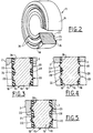
- la figure 2 est une vue en perspective du corps métallique de la bague du dispositif d'étanchéité,
- la figure 3 est une vue en coupe schématique pour illustrer la déformation du dispositif d'étanchéité après montage,
- la figure 4 est une vue en coupe schématique pour illustrer la déformation du dispositif d'étanchéité lors de la phase de balistique intérieure, et
- la figure 5 est une vue en coupe schématique pour illustrer la déformation du dispositif d'étanchéité pendant la phase de balistique extérieure et avant le dépotage de l'obus.
- FIG. 1 is a partial perspective view of a cargo shell fitted with a sealing device according to the invention and mounted between the base and the envelope of the cargo shell,
- FIG. 2 is a perspective view of the metal body of the ring of the sealing device,
- FIG. 3 is a schematic sectional view to illustrate the deformation of the sealing device after mounting,
- FIG. 4 is a schematic sectional view to illustrate the deformation of the sealing device during the interior ballistics phase, and
- Figure 5 is a schematic sectional view to illustrate the deformation of the sealing device during the exterior ballistics phase and before the stripping of the shell.
L'obus cargo 1 illustré partiellement à la figure 1 comprend une enveloppe métallique tubulaire 2, dont la partie arrière est fermée par un culot métallique 3 relié à l'enveloppe 2 au moyen d'une liaison mécanique étanche destinée à se rompre pour permettre l'éjection d'une charge utile (non représentée) contenue dans l'enveloppe 2 après un certain temps de vol de l'obus cargo 1.The cargo shell 1 partially illustrated in FIG. 1 comprises a
La liaison mécanique étanche comprend une liaison mécanique proprement dite 5 et un dispositif d'étanchéité 6, qui vont être détaillés ci-après.The sealed mechanical connection comprises a mechanical connection proper 5 and a
Le culot 3 présente vers son extrémité adjacente à la partie arrière de l'enveloppe 2, une réduction de diamètre extérieur qui délimite une jupe cylindrique 7, dont le diamètre extérieur est légèrement inférieur au diamètre intérieur de la partie arrière de l'enveloppe 2, et un épaulement annulaire 9 radialement externe entre la jupe 7 et la partie de plus grand diamètre du culot 3.The
Le culot 3 par l'intermédiaire de sa jupe 7 peut être ainsi emmanché librement dans la partie arrière de l'enveloppe 2. Le culot 3 est ensuite retenu par un ensemble de vis 10 qui présentent une tête 11 et une tige filetée 12 qui sont séparées l'une de l'autre par une amorce de rupture qui est destinée à favoriser la rupture de chaque vis lors du dépotage. Cette amorce de rupture peut être constituée par la différence de diamètre entre la tête et la tige des vis ou par un amincissement local du diamètre des tiges. La tête 11 de chaque vis traverse librement une ouverture 13 prévue dans la paroi de l'enveloppe 2 pour que la tige filetée 12 vienne se visser dans la jupe 7 du culot 3.The
Le dispositif d'étanchéité 6 est constitué d'une bague 15 comprenant un corps annulaire métallique 16. En se reportant à la figure 2, les deux faces d'extrémité annulaire 18 du corps métallique 16 comportent des moyens d'ancrage 20 en saillie. Ces moyens d'ancrage 20 sont par exemple constitués par deux nervures 22, annulaires et concentriques, ayant sensiblement la même hauteur. En section droite, chaque nervure 22 a globalement une forme triangulaire. Ces deux nervures 22 délimitent entre elles une gorge centrale annulaire 24 avec, de part et d'autre des nervures 22, deux demi-gorges latérales annulaires 26. A titre d'exemple, la bague 15 s'étend sur une longueur axiale de l'ordre de 4 mm, et chaque nervure a une hauteur de l'ordre de 0,5 mm. Les deux faces d'extrémité annulaires 18 du corps métallique 16 de la bague 15 sont chacune recouvertes d'une couche d'élastomère 28 ayant une épaisseur égale ou supérieure à la hauteur des nervures 22.The
Le corps métallique 16 de la bague 15 est de préférence en un acier ayant une résistance élastique élevée supérieure à celle du métal constituant l'enveloppe et le culot, cette résistance est par exemple supérieure à 2000 Mpa. Le corps métallique 16 peut avantageusement subir un traitement thermique afin d'obtenir les caractéristiques souhaitées, par exemple une trempe. La couche d'élastomère 28 peut être du type silicone, nitrile, néoprène ou polychloroprène.The
D'une façon connue en soi, une ceinture 30 solidaire de la paroi externe de l'enveloppe 2 est destinée à prendre les rayures d'un tube d'une arme (non représentée) afin d'imprimer à l'obus, lors du tir, une rotation qui le stabilisera.In a manner known per se, a
Au montage, la bague 15 est rapportée librement autour de la jupe 7 du culot 3. Le culot 3 est ensuite engagé librement à l'intérieur de l'enveloppe et sa fixation est assurée par l'intermédiaire de vis 10.During assembly, the
L'épaisseur de la bague 15 est telle qu'une fois le culot 3 fixé à l'enveloppe 2, la bague 15 est comprimée axialement de manière à ce que les extrémités pointues des nervures 22 des faces d'extrémité 18 de la bague pénètrent dans les deux surfaces d'appui associées et respectivement constituées par la surface d'extrémité libre 2a de l'enveloppe et l'épaulement 9 du culot 3.The thickness of the
Ainsi, comme cela est illustré à la figure 3, une fois le culot 3 fixé à l'enveloppe 2 de l'obus, les matériaux métalliques de l'enveloppe 2 et du culot 3 ont subi au moment du montage une déformation élastique, et l'étanchéité procurée par la bague 15 est assurée par les nervures 22 qui, du fait de leur grande dureté, se sont en partie ancrées dans l'enveloppe 2 et le culot 3 d'une part, et par la mise en compression de la couche d'élastomère 28 d'autre part. Lorsque la couche d'élastomère 28 a une épaisseur supérieure à la hauteur des nervures 22, ces dernières transperçent la couche 28 au moment du montage du culot 3 sur l'enveloppe 2.Thus, as illustrated in FIG. 3, once the
La liaison mécanique 5 entre le culot 3 et l'enveloppe 2 est ainsi protégée par la bague 15 contre l'agression des agents extérieurs pendant les phases de stockage, de logitisque et de maintenance.The
Lors du coup de canon, c'est-à-dire lorsque l'obus 1 est tiré, l'énorme pression engendrée après initiation de la charge propulsive, associée à l'inertie de l'obus, provoque une déformation plastique de l'enveloppe 2 et du culot 3, ainsi qu'une pénétration plus importante des nervures 22 dans l'enveloppe 2 et le culot 3, ainsi qu'une mise en compression plus importante de la couche d'élastomère 28, comme cela est illustré à la figure 4. L'étanchéité est donc bien assurée au cours de la phase de balistique intérieure, et seule la partie de la couche d'élastomère 28 située au niveau de la demi-gorge externe 26 de chaque face d'extrémité 18 de la bague 15, sera endommagée au contact des gaz propulsifs. A la sortie du tube du canon, les contraintes appliquées par les gaz propulsifs diminuent, si bien que les nervures 22 ne vont plus être en contact avec l'enveloppe 2 et le culot 3 du fait que ces derniers ont subi une déformation plastique au départ du coup. L'étanchéité est cependant assurée par la couche d'élastomère 28, comme cela est illustré à la figure 5. Ainsi, la continuité de l'étanchéité vis-à-vis d'agents extérieurs est assurée jusqu'au dépotage de l'obus.Bien entendu, les moyens d'ancrage ne sont pas limités à deux nervures ayant, en section droite une forme globalement triangulaire. En particulier, la section droite des nervures peut être trapézoïdale, voire arrondie.During the cannon shot, that is to say when the shell 1 is fired, the enormous pressure generated after initiation of the propellant charge, associated with the inertia of the shell, causes a plastic deformation of the
Claims (10)
Applications Claiming Priority (2)
| Application Number | Priority Date | Filing Date | Title |
|---|---|---|---|
| FR9510808A FR2738909B1 (en) | 1995-09-15 | 1995-09-15 | SEALING DEVICE MOUNTED BETWEEN THE ENCLOSURE AND THE BASE OF A CARGO SHELL |
| FR9510808 | 1995-09-15 |
Publications (1)
| Publication Number | Publication Date |
|---|---|
| EP0763707A1 true EP0763707A1 (en) | 1997-03-19 |
Family
ID=9482566
Family Applications (1)
| Application Number | Title | Priority Date | Filing Date |
|---|---|---|---|
| EP96401939A Ceased EP0763707A1 (en) | 1995-09-15 | 1996-09-11 | Sealing device mounted between the enveloppe and the base of a cargo projectile |
Country Status (2)
| Country | Link |
|---|---|
| EP (1) | EP0763707A1 (en) |
| FR (1) | FR2738909B1 (en) |
Citations (4)
| Publication number | Priority date | Publication date | Assignee | Title |
|---|---|---|---|---|
| GB2075155A (en) * | 1980-04-24 | 1981-11-11 | Diehl Gmbh & Co | Ejector cartridge for aircraft self-protection against radar |
| WO1991018227A1 (en) * | 1990-05-23 | 1991-11-28 | Olin Corporation | Seal ring for pyrotechnically initiated projectile |
| EP0519890A1 (en) * | 1991-06-18 | 1992-12-23 | Ab Bofors | A method and an apparatus for sealing an explosive charge compartment in a shell |
| US5398587A (en) * | 1994-03-23 | 1995-03-21 | The United States Of America As Represented By The Secretary Of The Navy | Gas-propelled line deployment system |
-
1995
- 1995-09-15 FR FR9510808A patent/FR2738909B1/en not_active Expired - Fee Related
-
1996
- 1996-09-11 EP EP96401939A patent/EP0763707A1/en not_active Ceased
Patent Citations (4)
| Publication number | Priority date | Publication date | Assignee | Title |
|---|---|---|---|---|
| GB2075155A (en) * | 1980-04-24 | 1981-11-11 | Diehl Gmbh & Co | Ejector cartridge for aircraft self-protection against radar |
| WO1991018227A1 (en) * | 1990-05-23 | 1991-11-28 | Olin Corporation | Seal ring for pyrotechnically initiated projectile |
| EP0519890A1 (en) * | 1991-06-18 | 1992-12-23 | Ab Bofors | A method and an apparatus for sealing an explosive charge compartment in a shell |
| US5398587A (en) * | 1994-03-23 | 1995-03-21 | The United States Of America As Represented By The Secretary Of The Navy | Gas-propelled line deployment system |
Also Published As
| Publication number | Publication date |
|---|---|
| FR2738909B1 (en) | 1997-12-05 |
| FR2738909A1 (en) | 1997-03-21 |
Similar Documents
| Publication | Publication Date | Title |
|---|---|---|
| WO2014184451A1 (en) | Flangeless cartridge | |
| EP0180515A1 (en) | Drag reduction device for ammunition, and ammunition therefor | |
| CH636191A5 (en) | SOCKET AND FIREARMS CARTRIDGE COMPRISING SUCH A SOCKET. | |
| EP0626555A1 (en) | Practice projectile and method for fabrication | |
| EP0048644B1 (en) | Vaned projectile of the arrow type | |
| EP1712873A1 (en) | Adapter element for firing a mortar grenade from a gun barrel | |
| EP0267090B1 (en) | Rifle grenade | |
| EP0659264B1 (en) | Artillery shell propellant gas sealing device | |
| EP0763707A1 (en) | Sealing device mounted between the enveloppe and the base of a cargo projectile | |
| EP0268535B1 (en) | Slipping obturator ring for projectiles of all calibres | |
| CA1334908C (en) | Shell fin deployment device | |
| EP1693646B1 (en) | Driving band fo artillery projectile | |
| FR2724450A1 (en) | DOUBLE PENETRATION HUNTING BALL WITH REDUCED RANGE | |
| FR2665762A1 (en) | PROJECTILES. | |
| FR2699659A1 (en) | Breakable join device between front and rear sections of munition | |
| EP4025865A1 (en) | Anti-aircraft shell for telescoped ammunition with double unlocking | |
| EP0526316B1 (en) | Ammunition, particularly of the telescoped type | |
| EP0530287B1 (en) | Centrally sealed twin launch system | |
| FR2927417A1 (en) | OBUS OF DISPERSION OF PROJECTILES | |
| EP1023573B1 (en) | Launcher with enhanced tightness for ammunitions comprising a launcher associated with a sub-projectile | |
| FR2567197A1 (en) | Powder propulsion unit for projectile fired in a launching tube | |
| FR2679644A1 (en) | Payload transporter device | |
| EP0661513A1 (en) | Projectile propulsion assembly | |
| FR2608266A1 (en) | IMPROVEMENTS TO IMPACT CONTACTORS OR CONTACTOR OGIVES FOR PROJECTILES | |
| FR2604248A1 (en) | Projectile |
Legal Events
| Date | Code | Title | Description |
|---|---|---|---|
| PUAI | Public reference made under article 153(3) epc to a published international application that has entered the european phase |
Free format text: ORIGINAL CODE: 0009012 |
|
| AK | Designated contracting states |
Kind code of ref document: A1 Designated state(s): CH DE ES FI GB IT LI NL SE |
|
| 17P | Request for examination filed |
Effective date: 19970421 |
|
| 17Q | First examination report despatched |
Effective date: 19990218 |
|
| GRAG | Despatch of communication of intention to grant |
Free format text: ORIGINAL CODE: EPIDOS AGRA |
|
| STAA | Information on the status of an ep patent application or granted ep patent |
Free format text: STATUS: THE APPLICATION HAS BEEN REFUSED |
|
| 18R | Application refused |
Effective date: 20000127 |