EP0763366A1 - Biegewerkzeug für eines Saug- und Koagulationsinstrument - Google Patents
Biegewerkzeug für eines Saug- und Koagulationsinstrument Download PDFInfo
- Publication number
- EP0763366A1 EP0763366A1 EP96114551A EP96114551A EP0763366A1 EP 0763366 A1 EP0763366 A1 EP 0763366A1 EP 96114551 A EP96114551 A EP 96114551A EP 96114551 A EP96114551 A EP 96114551A EP 0763366 A1 EP0763366 A1 EP 0763366A1
- Authority
- EP
- European Patent Office
- Prior art keywords
- tubular extension
- suction
- coagulator
- bending tool
- bending
- Prior art date
- Legal status (The legal status is an assumption and is not a legal conclusion. Google has not performed a legal analysis and makes no representation as to the accuracy of the status listed.)
- Ceased
Links
Images
Classifications
-
- A—HUMAN NECESSITIES
- A61—MEDICAL OR VETERINARY SCIENCE; HYGIENE
- A61B—DIAGNOSIS; SURGERY; IDENTIFICATION
- A61B18/00—Surgical instruments, devices or methods for transferring non-mechanical forms of energy to or from the body
- A61B18/04—Surgical instruments, devices or methods for transferring non-mechanical forms of energy to or from the body by heating
- A61B18/12—Surgical instruments, devices or methods for transferring non-mechanical forms of energy to or from the body by heating by passing a current through the tissue to be heated, e.g. high-frequency current
- A61B18/14—Probes or electrodes therefor
- A61B18/1402—Probes for open surgery
-
- A—HUMAN NECESSITIES
- A61—MEDICAL OR VETERINARY SCIENCE; HYGIENE
- A61M—DEVICES FOR INTRODUCING MEDIA INTO, OR ONTO, THE BODY; DEVICES FOR TRANSDUCING BODY MEDIA OR FOR TAKING MEDIA FROM THE BODY; DEVICES FOR PRODUCING OR ENDING SLEEP OR STUPOR
- A61M1/00—Suction or pumping devices for medical purposes; Devices for carrying-off, for treatment of, or for carrying-over, body-liquids; Drainage systems
- A61M1/84—Drainage tubes; Aspiration tips
-
- A—HUMAN NECESSITIES
- A61—MEDICAL OR VETERINARY SCIENCE; HYGIENE
- A61B—DIAGNOSIS; SURGERY; IDENTIFICATION
- A61B17/00—Surgical instruments, devices or methods, e.g. tourniquets
- A61B17/24—Surgical instruments, devices or methods, e.g. tourniquets for use in the oral cavity, larynx, bronchial passages or nose; Tongue scrapers
-
- A—HUMAN NECESSITIES
- A61—MEDICAL OR VETERINARY SCIENCE; HYGIENE
- A61M—DEVICES FOR INTRODUCING MEDIA INTO, OR ONTO, THE BODY; DEVICES FOR TRANSDUCING BODY MEDIA OR FOR TAKING MEDIA FROM THE BODY; DEVICES FOR PRODUCING OR ENDING SLEEP OR STUPOR
- A61M2209/00—Ancillary equipment
- A61M2209/04—Tools for specific apparatus
Definitions
- This invention relates to a combination suction coagulator and associated custom bending tool; and it more particularly relates to such a suction coagulator that includes a PTFE (poly tetrafluorethylene) insulated extremity that is custom bendable with a dedicated bending tool, the combined coagulator and tool being disposable after each use.
- PTFE poly tetrafluorethylene
- suction/coagulation instruments are more effective when their extending extremities are positioned essentially normally (i.e., at right angles) to the patient's work surface. Accordingly, there has been a need to include a provision of bendability to the distal extremities of the extending tubular members so as to accommodate differences in patient physiologies.
- the improved suction coagulator according to the invention hereof includes a handle portion for gripping and manipulation, a hollow tubular extension having a proximal end mounted within the handle and a distal portion extending outwardly from the handle. Included within the handle is an aperture in communication with the interior of the tubular extension for controlling suction therein imparted by a separate source of vacuum such as a conventional vacuum pump.
- a dedicated bending tool is provided for manipulation in cooperative combination with the distal portion of the tubular extension so as to provide a facilitated way of custom bending the distal portion according to the particular physiology of a patient on whom a surgical procedure is to be employed.
- the bending tool is generally elongated and includes at one end a recess that is slightly larger in diameter than the outer diameter of the distal end of the tubular extension.
- a mandrel pin Centrally located within the recess is a mandrel pin that is configured to conform to the interior cross sectional geometry of the tubular extension while being only slightly lesser in cross section so as to permit the end of the tubular extension to be slid thereover while retaining engagement therewith.
- Extending in axial alignment with the mandrel pin is a channel that essentially conforms to the exterior surface shape of the tubular extension so as to receive the same in mating and engaging relationship as the distal end of the tubular extension is mounted on the mandrel pin and the tool is manipulated to bend the distal end.
- the tubular extension is trapped by the combination of mandrel pin and channel so that it can be bent without collapsing or significantly changing the interior cross section of the tubular extension.
- the geometry of the channel and mandrel pin are such that a curved radius of the channel controls the maximum amount of bend allowed so the tubing does not break or collapse.
- a suction coagulator and its customizing tool are combined, thereby facilitating availability and use.
- the customizing tool is dedicated to the geometrical configuration of the suction coagulator, thereby facilitating its use.
- the customizing tool is generally elongated and is fitted at one end with a mandrel pin and associated bending channel thereby to provide for controlled incremental bending while maintaining the internal cross section of an engaging tubular extension essentially unchanged.
- the customizing tool includes a cooperative flexible stylet at the opposite end of the tool from that of the mandrel pin so as to provide for ready removal of unwanted material that may otherwise accumulate within the tubular extension during an operative procedure.
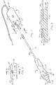
- Suction coagulator 10 is seen to include a handle portion 12 that may be made of any of a variety of well known plastic or similar materials such as polystyrenes, polycarbonates, and polyamides, but ABS lacrylonitrile-butadiene-styrened polymers are preferred. Its exterior geometrical configuration includes generally concave surface 13 and concave flutes 14 which are provided to facilitate holding and manipulation.
- Extension 18 is preferably circular in cross-section, although non-circular geometries can also be utilized. Included on the exterior surface of extension 18 is a thin insulating coating 18a, which is preferably a thin polyolefin shrink polymer such as polyethylene or polypropylene. Also shown at the extreme distal end of extension 18 is a further coating 19 over coating 18a.
- Such coating 19 extends for only 1 or 2 centimeters and is a polytetrafluoroethylene (PTFE) to help minimize eschar buildup and adherence. Coating 19 is optional.
- Power cable 17 is provided for connection to a conventional source of coagulating power.
- Cooperative custom bending tool 11 is seen to include a main body 20 that is generally rectangular in shape with an essentially rectangular bottom 21 and a modified and partially curved top 22. Thus, as shown, its length is greater than its width which, in turn is greater than its thickness. At one end there is a first surface 23 in which there is formed a preferably cylindrical recess 24 within which there is axially disposed a mandrel pin 25; and extending outwardly and radially from recess 24 is curved channel 26.
- a surface 28 ( Figure 3) through which there extends outwardly a flexible stylet 29 having a solid end 30 of diameter essentially equal to but minutely smaller than the internal diameter of hollow tubular extension 18 thus providing for convenient removal from the interior of extension 18 of any coagulated blood or tissue that may accumulate there during use.
- End 30 may be inserted into extension 18 and pushed therethrough to move undesired accumulations to the rear where they are sucked out by the aforementioned suction.
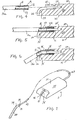
- FIG. 3 it will be seen to be a section taken along section lines 3-3 of Figure 2. There, it will be seen are the aforementioned partially curved top 22, first surface 23, cylindrical recess 24, mandrel pin 25, curved channel 26, opposite end 27, surface 28 and flexible stylet 29.
- Figure 4 illustrates the combination of the instrument and tool with the distal end 31 of hollow, tubular extension 18 in axial alignment with cylindrical recess 24 and mandrel pin 25 so as to be ready for the engagement as depicted in Figure 5.
- Figure 5 the combination is shown with distal end in place within recess 24 so that the mandrel pin 25 slidably projects into the hollow interior 33. In this position, the combination is ready for bending force to be applied to tool main body 20 or to tubular extension 18.
- Figure 6 shows the radius of the bend following the curvature 35 of curved channel 26.
- the recess 24 within which is the axially positioned mandrel pin 25 that is configured to conform to the interior cross sectional geometry of the hollow interior 33 of the tubular extension 18 while being only slightly lesser in cross section so as to permit the end 34 of the tubular extension to be slid thereover while retaining engagement therewith.
- the channel 26 that essentially conforms to the exterior surface shape of the tubular extension so as to receive the same in mating and engaging relationship as the distal end of the tubular extension is mounted on the mandrel pin and the tool is manipulated to bend the distal end.
- the distal portion 34 of the tubular extension 18 is trapped by the combination of mandrel pin 25 and channel 26 so that portion 34 can be bent without collapsing or significantly changing the interior cross section of the tubular extension.
- the geometry of the channel 26 and mandrel pin 25 are such that the radius of curvature 35 controls the maximum amount of bend allowed so the tubing does not break or collapse.
- the customizing tool 11 includes a cooperative flexible stylet 29 at the opposite end of the tool from that of the mandrel pin 25 so as to provide for ready removal of unwanted material that may otherwise accumulate within the tubular extension 18 during an operative procedure.
- flexible stylet 29 has a solid end 30 (Figure 1) of diameter essentially equal to but minutely smaller than the internal diameter of hollow tubular extension 18 thus providing for convenient removal from the interior of extension 18 of coagulated blood or tissue that may accumulate there during use. End 30 may be inserted into extension 18 (as shown in Figure 7) and pushed therein sufficiently to move any undesired accumulation to the rear of tube 18 where it is sucked out by the aforementioned suction accessory.
Applications Claiming Priority (2)
| Application Number | Priority Date | Filing Date | Title |
|---|---|---|---|
| US08/529,227 US5591141A (en) | 1995-09-15 | 1995-09-15 | Suction coagulator bending tool |
| US529227 | 1995-09-15 |
Publications (1)
| Publication Number | Publication Date |
|---|---|
| EP0763366A1 true EP0763366A1 (de) | 1997-03-19 |
Family
ID=24109039
Family Applications (1)
| Application Number | Title | Priority Date | Filing Date |
|---|---|---|---|
| EP96114551A Ceased EP0763366A1 (de) | 1995-09-15 | 1996-09-11 | Biegewerkzeug für eines Saug- und Koagulationsinstrument |
Country Status (8)
| Country | Link |
|---|---|
| US (1) | US5591141A (de) |
| EP (1) | EP0763366A1 (de) |
| JP (1) | JPH0975448A (de) |
| KR (1) | KR100225877B1 (de) |
| CN (1) | CN1145773A (de) |
| AU (1) | AU705312B2 (de) |
| NZ (1) | NZ286638A (de) |
| TW (1) | TW299238B (de) |
Families Citing this family (35)
| Publication number | Priority date | Publication date | Assignee | Title |
|---|---|---|---|---|
| WO1997000646A1 (en) | 1995-06-23 | 1997-01-09 | Gyrus Medical Limited | An electrosurgical instrument |
| US6293942B1 (en) | 1995-06-23 | 2001-09-25 | Gyrus Medical Limited | Electrosurgical generator method |
| US6015406A (en) | 1996-01-09 | 2000-01-18 | Gyrus Medical Limited | Electrosurgical instrument |
| US6780180B1 (en) | 1995-06-23 | 2004-08-24 | Gyrus Medical Limited | Electrosurgical instrument |
| BR9609421A (pt) | 1995-06-23 | 1999-05-18 | Gyrus Medical Ltd | Instrumento eletrocirúrgico |
| US6013076A (en) | 1996-01-09 | 2000-01-11 | Gyrus Medical Limited | Electrosurgical instrument |
| US6090106A (en) | 1996-01-09 | 2000-07-18 | Gyrus Medical Limited | Electrosurgical instrument |
| US6565561B1 (en) | 1996-06-20 | 2003-05-20 | Cyrus Medical Limited | Electrosurgical instrument |
| GB9612993D0 (en) | 1996-06-20 | 1996-08-21 | Gyrus Medical Ltd | Electrosurgical instrument |
| GB2314274A (en) | 1996-06-20 | 1997-12-24 | Gyrus Medical Ltd | Electrode construction for an electrosurgical instrument |
| GB9626512D0 (en) | 1996-12-20 | 1997-02-05 | Gyrus Medical Ltd | An improved electrosurgical generator and system |
| GB2327352A (en) * | 1997-07-18 | 1999-01-27 | Gyrus Medical Ltd | Electrosurgical instrument |
| GB9807303D0 (en) | 1998-04-03 | 1998-06-03 | Gyrus Medical Ltd | An electrode assembly for an electrosurgical instrument |
| US20040115477A1 (en) * | 2002-12-12 | 2004-06-17 | Bruce Nesbitt | Coating reinforcing underlayment and method of manufacturing same |
| US7766844B2 (en) * | 2004-04-21 | 2010-08-03 | Smith & Nephew, Inc. | Surgical instrument aspiration valve |
| US7909851B2 (en) * | 2006-02-03 | 2011-03-22 | Biomet Sports Medicine, Llc | Soft tissue repair device and associated methods |
| US8814861B2 (en) | 2005-05-12 | 2014-08-26 | Innovatech, Llc | Electrosurgical electrode and method of manufacturing same |
| US7147634B2 (en) * | 2005-05-12 | 2006-12-12 | Orion Industries, Ltd. | Electrosurgical electrode and method of manufacturing same |
| US9226688B2 (en) | 2009-03-10 | 2016-01-05 | Medtronic Xomed, Inc. | Flexible circuit assemblies |
| US9226689B2 (en) | 2009-03-10 | 2016-01-05 | Medtronic Xomed, Inc. | Flexible circuit sheet |
| US8504139B2 (en) | 2009-03-10 | 2013-08-06 | Medtronic Xomed, Inc. | Navigating a surgical instrument |
| CN103068332B (zh) | 2010-04-30 | 2016-05-04 | 美敦力施美德公司 | 被导航的可塑性外科器械 |
| US10617374B2 (en) | 2011-01-28 | 2020-04-14 | Medtronic Navigation, Inc. | Method and apparatus for image-based navigation |
| US9974501B2 (en) | 2011-01-28 | 2018-05-22 | Medtronic Navigation, Inc. | Method and apparatus for image-based navigation |
| US10492868B2 (en) | 2011-01-28 | 2019-12-03 | Medtronic Navigation, Inc. | Method and apparatus for image-based navigation |
| EP2686030B1 (de) | 2011-03-14 | 2021-10-20 | Neuro Enterprises, LLC | Selbstreinigende medizinische absaugvorrichtung |
| US10098991B2 (en) | 2011-03-14 | 2018-10-16 | Neuroenterprises, Llc | Self-cleaning surgical suction device and method of use |
| US9144636B2 (en) | 2011-03-14 | 2015-09-29 | Neuroenterprises, Llc | Self-cleaning surgical suction device with interchangeable tips |
| US8845618B2 (en) | 2011-08-25 | 2014-09-30 | H & M Innovations, Llc | Anti-clog suction tip apparatus and method |
| EP2747805B1 (de) | 2011-08-25 | 2021-10-27 | H&M Innovations, LLC | Verstopfungsverhindernde saugspitze |
| US9750486B2 (en) | 2011-10-25 | 2017-09-05 | Medtronic Navigation, Inc. | Trackable biopsy needle |
| US10278729B2 (en) | 2013-04-26 | 2019-05-07 | Medtronic Xomed, Inc. | Medical device and its construction |
| JP2016104069A (ja) * | 2014-12-01 | 2016-06-09 | 高島産業株式会社 | 医療用管状器具および医療用管状器具システム |
| JP2022537959A (ja) * | 2019-06-18 | 2022-08-31 | スミス アンド ネフュー インコーポレイテッド | 曲げツールおよびその使用方法 |
| US11612404B2 (en) | 2019-08-14 | 2023-03-28 | Biosense Webster (Israel) Ltd. | Jig for straightening and bending a malleable tool |
Citations (5)
| Publication number | Priority date | Publication date | Assignee | Title |
|---|---|---|---|---|
| US3828780A (en) * | 1973-03-26 | 1974-08-13 | Valleylab Inc | Combined electrocoagulator-suction instrument |
| US4481803A (en) * | 1983-03-18 | 1984-11-13 | Teledyne Industries, Inc. | Method for eliminating distortion at the end of a tube bend |
| US4686981A (en) * | 1983-03-28 | 1987-08-18 | Laszlo Forintos | Surgical instrument especially for performing neurosurgical operations |
| US5295827A (en) * | 1991-11-18 | 1994-03-22 | Minnesota Mining And Manufacturing Company | Syringe tip forming apparatus |
| US5411514A (en) * | 1992-09-30 | 1995-05-02 | Linvatec Corporation | Bendable variable angle rotating shaver |
Family Cites Families (9)
| Publication number | Priority date | Publication date | Assignee | Title |
|---|---|---|---|---|
| US1903436A (en) * | 1931-07-03 | 1933-04-11 | Brown Edmund | Method of and means for the manufacture of pipe fittings |
| DE876800C (de) * | 1951-04-14 | 1953-05-18 | Chemische Werke Huels Ges Mit | Verschlussstopfen fuer zu biegende Rohre |
| US2824475A (en) * | 1957-04-29 | 1958-02-25 | Rolando John | Hand tool for bending a wire end |
| US3470876A (en) * | 1966-09-28 | 1969-10-07 | John Barchilon | Dirigible catheter |
| US3521620A (en) * | 1967-10-30 | 1970-07-28 | William A Cook | Vascular coil spring guide with bendable tip |
| JPS63192519A (ja) * | 1987-02-04 | 1988-08-09 | Honda Motor Co Ltd | 角パイププレスベンダ− |
| JPH01186221A (ja) * | 1988-01-21 | 1989-07-25 | Tsuji Giken Kogyo Kk | 管の曲げ加工方法 |
| US4898577A (en) * | 1988-09-28 | 1990-02-06 | Advanced Cardiovascular Systems, Inc. | Guiding cathether with controllable distal tip |
| US5201210A (en) * | 1991-11-12 | 1993-04-13 | Stein Iii William | Needle bending device |
-
1995
- 1995-09-15 US US08/529,227 patent/US5591141A/en not_active Expired - Fee Related
-
1996
- 1996-05-22 NZ NZ286638A patent/NZ286638A/en unknown
- 1996-05-23 TW TW085106122A patent/TW299238B/zh active
- 1996-06-14 CN CN96108221A patent/CN1145773A/zh active Pending
- 1996-07-18 JP JP8189449A patent/JPH0975448A/ja active Pending
- 1996-09-11 EP EP96114551A patent/EP0763366A1/de not_active Ceased
- 1996-09-12 KR KR1019960039555A patent/KR100225877B1/ko not_active IP Right Cessation
- 1996-09-16 AU AU65644/96A patent/AU705312B2/en not_active Ceased
Patent Citations (5)
| Publication number | Priority date | Publication date | Assignee | Title |
|---|---|---|---|---|
| US3828780A (en) * | 1973-03-26 | 1974-08-13 | Valleylab Inc | Combined electrocoagulator-suction instrument |
| US4481803A (en) * | 1983-03-18 | 1984-11-13 | Teledyne Industries, Inc. | Method for eliminating distortion at the end of a tube bend |
| US4686981A (en) * | 1983-03-28 | 1987-08-18 | Laszlo Forintos | Surgical instrument especially for performing neurosurgical operations |
| US5295827A (en) * | 1991-11-18 | 1994-03-22 | Minnesota Mining And Manufacturing Company | Syringe tip forming apparatus |
| US5411514A (en) * | 1992-09-30 | 1995-05-02 | Linvatec Corporation | Bendable variable angle rotating shaver |
Also Published As
| Publication number | Publication date |
|---|---|
| US5591141A (en) | 1997-01-07 |
| AU705312B2 (en) | 1999-05-20 |
| CN1145773A (zh) | 1997-03-26 |
| AU6564496A (en) | 1997-03-20 |
| KR100225877B1 (ko) | 1999-10-15 |
| NZ286638A (en) | 1997-09-22 |
| TW299238B (en) | 1997-03-01 |
| JPH0975448A (ja) | 1997-03-25 |
| KR970014781A (ko) | 1997-04-28 |
Similar Documents
| Publication | Publication Date | Title |
|---|---|---|
| US5591141A (en) | Suction coagulator bending tool | |
| US11612682B2 (en) | Ergonomic tubing attachment for medical apparatus | |
| US6802835B2 (en) | Apparatus and method for using a steerable catheter device | |
| US8469993B2 (en) | Endoscopic instruments | |
| US6616683B1 (en) | Method of making miniaturized surgical forceps | |
| US8850676B2 (en) | Guidewire loading tool for a catheter | |
| US20060212056A1 (en) | Surgical instrument | |
| WO1995001755A1 (en) | Disposable aspiration tip for a cautery handpiece | |
| US20040230204A1 (en) | Flexible connection catheter tunneler and methods for using the same | |
| US6344038B1 (en) | Surgical anti-friction device | |
| WO2001019255A1 (en) | Adjustable stiffness membrane scraper | |
| US7131975B2 (en) | Apparatus and methods for straightening angled tissue cutting instruments | |
| CN110934634A (zh) | 流体系统连接器 | |
| US20110245599A1 (en) | Surgical Handpiece For Endoscopic Resection | |
| US7632254B1 (en) | Device for splitting the tubular body of a catheter or sheath | |
| EP2913014B1 (de) | Überrohr | |
| US20220346809A1 (en) | Surgical Instrument System and Irrigation Sleeve | |
| US20230191017A1 (en) | Ergonomic Tubing Attachment for Medical Apparatus | |
| JPH0588552U (ja) | 医療用剥離吸引嘴管 | |
| JP4095132B2 (ja) | 内視鏡用処置具 | |
| JPH09154847A (ja) | 内視鏡下外科手術用処置具 | |
| CN116234509A (zh) | 医疗铰接装置和使用其的方法 |
Legal Events
| Date | Code | Title | Description |
|---|---|---|---|
| PUAI | Public reference made under article 153(3) epc to a published international application that has entered the european phase |
Free format text: ORIGINAL CODE: 0009012 |
|
| AK | Designated contracting states |
Kind code of ref document: A1 Designated state(s): DE FR GB IT |
|
| 17P | Request for examination filed |
Effective date: 19970911 |
|
| GRAG | Despatch of communication of intention to grant |
Free format text: ORIGINAL CODE: EPIDOS AGRA |
|
| RIC1 | Information provided on ipc code assigned before grant |
Free format text: 7A 61M 1/00 A, 7A 61B 18/14 B |
|
| 17Q | First examination report despatched |
Effective date: 20020325 |
|
| STAA | Information on the status of an ep patent application or granted ep patent |
Free format text: STATUS: THE APPLICATION HAS BEEN REFUSED |
|
| 18R | Application refused |
Effective date: 20020916 |