EP0762802A2 - Lautsprecher mit Mehrpunktantrieb - Google Patents
Lautsprecher mit Mehrpunktantrieb Download PDFInfo
- Publication number
- EP0762802A2 EP0762802A2 EP96114014A EP96114014A EP0762802A2 EP 0762802 A2 EP0762802 A2 EP 0762802A2 EP 96114014 A EP96114014 A EP 96114014A EP 96114014 A EP96114014 A EP 96114014A EP 0762802 A2 EP0762802 A2 EP 0762802A2
- Authority
- EP
- European Patent Office
- Prior art keywords
- diaphragm
- speaker
- magnetic circuit
- drive type
- valley
- Prior art date
- Legal status (The legal status is an assumption and is not a legal conclusion. Google has not performed a legal analysis and makes no representation as to the accuracy of the status listed.)
- Granted
Links
Images


Classifications
-
- H—ELECTRICITY
- H04—ELECTRIC COMMUNICATION TECHNIQUE
- H04R—LOUDSPEAKERS, MICROPHONES, GRAMOPHONE PICK-UPS OR LIKE ACOUSTIC ELECTROMECHANICAL TRANSDUCERS; DEAF-AID SETS; PUBLIC ADDRESS SYSTEMS
- H04R7/00—Diaphragms for electromechanical transducers; Cones
- H04R7/02—Diaphragms for electromechanical transducers; Cones characterised by the construction
- H04R7/12—Non-planar diaphragms or cones
-
- H—ELECTRICITY
- H04—ELECTRIC COMMUNICATION TECHNIQUE
- H04R—LOUDSPEAKERS, MICROPHONES, GRAMOPHONE PICK-UPS OR LIKE ACOUSTIC ELECTROMECHANICAL TRANSDUCERS; DEAF-AID SETS; PUBLIC ADDRESS SYSTEMS
- H04R9/00—Transducers of moving-coil, moving-strip, or moving-wire type
- H04R9/02—Details
- H04R9/025—Magnetic circuit
-
- H—ELECTRICITY
- H04—ELECTRIC COMMUNICATION TECHNIQUE
- H04R—LOUDSPEAKERS, MICROPHONES, GRAMOPHONE PICK-UPS OR LIKE ACOUSTIC ELECTROMECHANICAL TRANSDUCERS; DEAF-AID SETS; PUBLIC ADDRESS SYSTEMS
- H04R9/00—Transducers of moving-coil, moving-strip, or moving-wire type
- H04R9/06—Loudspeakers
- H04R9/063—Loudspeakers using a plurality of acoustic drivers
Definitions
- the present invention relates to a multi-point drive type speaker which drives a diaphragm with a plurality of voice coils.
- a conventional general cone type speaker is of the one-point drive type that the central base portion of a cone diaphragm is driven with a single voice coil.
- the half apex angle of a diaphragm is required to be made as small as possible, i.e., the cone is required to be as shallow as possible.
- the diaphragm is desired to be ultimately planar.
- the narrower the half apex angle i.e., the deeper the cone, the wider the reproduction frequency band and the broader the high frequency band can be reproduced.
- the wider the half apex angle i.e., the shallower the cone, the narrower the reproduction band.
- the present inventors have proposed a multi-point driver type speaker which solves the above problems of a conventional speaker (Japanese Patent Application No. 6-147046).
- This speaker drives a planer diaphragm with a plurality of voice coils and uses repulsion magnetic circuits with a repulsion magnetic field generated at the outer peripheral area of a center plate of magnetic material disposed between two magnets with the same polarities being faced each other.
- another embodiment is also proposed which shows an example of application to a cone type speaker.
- This multi-point speaker can be extremely thinned and the reproduction frequency band can be made wider than a one-point drive type speaker.
- the present invention has developed and improved a multi-point drive type speaker previously proposed to be most suitable for a vehicle door mount speaker.
- Figs. 8A and 8B show an example of a one-point drive type speaker (hereinafter called a "one-point drive type planar speaker SP1") using a conventional planar diaphragm 1f.
- a voice coil 2 is disposed which is driven by a repulsion magnetic circuit.
- the configuration of Fig. 8 was published in JP Laid-open Patent Gazette No. 06-28499 and is disclosed in US Patent Application No. 08/219,528 filed on March 29, 1994 and assigned to the same assignee as that of the present application.
- the repulsion magnetic circuit has a center plate 5 made of magnetic material disposed between two magnets M1 and M2 with the same polarities being faced each other.
- the voice coil 2 is disposed in a repulsion magnetic field generated at the peripheral area of the center plate 5.
- This one-point drive type planar speaker SP1 has a high frequency limit of about 700 to 900 Hz in the reproduction frequency band which is too narrow if the speaker is used as a general 2-way speaker. This speaker can be used therefore only as a low frequency band speaker.
- the present inventors manufactured a thin low frequency speaker system having the above configuration with a height of 728 mm, a width of 1028 mm, and a depth of 30 mm.
- a multi-point drive type planar speaker SP3 such as shown in Figs. 9A and 9B was manufactured.
- a planar diaphragm 1f generally the same as that of the one-point drive type planar speaker SP1 is used and driven at three points with a combination of three voice coils 2 and three repulsion magnetic circuits.
- This multi-point drive type planar speaker SP3 had a high frequency limit of about 2000 to 3000 Hz, was able to use as a woofer of a 2-way speaker system, and a vehicle door mount speaker system with a tweeter was actually manufactured.
- the multi-point drive type planar speaker SP3 has the following advantages over a generally used one-point drive type planar speaker SP1.
- the disadvantages are as follows. First, fractional vibrations are more likely to occur than a cone so that the diaphragm is required to be thick, increasing the weight of the diaphragm. Second, since there is no half apex angle, it is difficult to raise the high frequency limit.
- auxiliary diaphragm 1s called a wither or the like is mounted, such as shown in Figs. 10A and 10B, the high frequency limit can be raised without changing the diaphragm shape of the multi-point drive type planar speaker SP3 and the speaker can be used as a full-range one-point drive type cone speaker or the like.
- reference numeral 6 represents a frame.
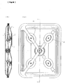
- Figs. 11A and 11B show an example of the configuration of a multi-point drive type cone speaker SP2 which drives a cone diaphragm 1c of a general cone type speaker at multiple points.
- This configuration has been disclosed as an example of application of the multi-point drive type speaker the inventors have proposed previously.
- driving such a cone 1c at multiple points results in a large mount depth of the cone and is not suitable for thinning.
- the configurations of Fig. 9A - Fig. 11B are disclosed in copending US application No. 08/451,497 filed on May 26, 1995 which was assigned to the same assignee as that of the present application.
- the cone diaphragm having a valley at the junction point with the center cap is integrally mounted with the center cap, and a plurality of voice coils, preferably three or more voice coils, are radially disposed along the valley or at the area near the valley to drive the diaphragm.
- the voice coil is driven by a repulsion magnetic circuit.
- a flat area is formed at the bottom of the valley area of the diaphragm.
- An adhesive margin formed at the end portion of a suspension such as a damper for supporting the diaphragm is adhered to the flat area.
- a corrugation portion of the damper is positioned under a dome.
- the diaphragm is formed with a horizontal surface at the area where the voice coil is mounted.
- a sloped area with an inclination angle relative to the horizontal surface is formed continuously with the horizontal surface.
- a cut-away area is formed in the diaphragm at the horizontal surface or at the sloped area and the voice coil is disposed at the cut-away area.
- An edge, a diaphragm mount, and the suspension may be molded integrally to adhere the integral mold to the diaphragm.
- Figs. 1A and 1B show a speaker according to an embodiment of the invention
- Fig. 1A is a plan view of a diaphragm
- Fig. 1B is a cross sectional view taken along line A-A of Fig. 1A.
- Figs. 2A and 2B show a speaker frame
- Fig. 2A is a plan view of the speaker frame
- Fig. 2B is a cross sectional view taken along line A-A of Fig. 2A.
- Figs. 3A and 3B show the frame, a damper shaft, and a magnetic circuit shaft, respectively mounted on the frame bottom
- Fig. 3A is a plan view thereof
- Fig. 3B is a cross sectional view taken along line A-A of Fig. 3A.
- Figs. 4A to 4C illustrate a process of mounting a diaphragm assembly of the speaker on the frame
- Fig. 4A is a cross sectional view of the diaphragm assembly
- Fig. 4B is a cross sectional view of the frame
- Fig. 4C is a cross sectional view illustrating the mount state.
- Fig. 5 is a cross sectional view-showing the mount state of a repulsion magnetic circuit on the magnetic circuit shaft.
- Figs. 6A and 6B show a finished speaker
- Fig. 6A is a plan view thereof
- Fig. 6B is a cross sectional view taken along line A-A of Fig. 6A.
- Figs. 7A to 7C show another embodiment of the speaker in which an edge, a damper, and a diaphragm mount are integrally molded and a diaphragm is mounted on the diaphragm mount
- Fig. 7A is a cross sectional view of the diaphragm
- Fig. 7B is a cross sectional view of the integral mold of the edge, damper, and diaphragm mount
- Fig. 7C is a cross sectional view showing the mount state of the diaphragm.
- Figs. 8A and 8B show a conventional one-point drive type planar speaker
- Fig. 8A is a plan view thereof
- Fig. 8B is a cross sectional view taken along line A-A of Fig. 8A.
- Figs. 9A and 9B show a speaker proposed by the present inventors and disclosed in JP Patent Application No. 6-147046
- Fig. 9A is a plan view thereof
- Fig. 9B is a cross sectional view taken along line A-A of Fig. 8A.
- Figs. 10A and 10B show a conventional speaker obtained by improving a multi-point drive type planar speaker
- Fig. 10A is a plan view thereof
- Fig. 10B is a cross sectional view taken along line A-B of Fig. 10A.
- Figs. 11A and 11B show a conventional multi-point drive type cone speaker for driving a cone diaphragm at multiple points
- Fig. 11A is a plan view thereof
- Fig. 11B is a cross sectional view taken along line A-0-B of Fig. 11A.
- a diaphragm 1cd of 107 mm diameter is made of paper board and has generally a shallow W-character shape as shown in Fig. 1B.
- a valley 11 of 10.9 mm deep is formed at the position remote by 27.8 mm in the radial direction from the center of the diaphragm 1cd.
- a horizontal adhesive margin 12 of about 3mm wide is formed at the valley 11.
- Lines coupling both sides of the adhesive margin 12 to the center apex and outer apex of the diaphragm 1cd form curves having a radius of 60 mm, the portion between the adhesive margin 12 of the valley 11 and the outer apex forms a cone 1c and the portion between the adhesive margin 12 and the center apex forms a dome 1d.
- the cone 1c and dome 1d constitute an integral mold of the diaphragm 1cd.
- each voice coil mount 14 has a circular flat portion of 22 mm diameter and a hole formed in the flat portion and having a diameter (in this embodiment, 20.5 mm diameter) corresponding to the maximum diameter of a voice coil 2.
- the voice coil mount 14 has a conical slope 13 with an inclination angle of about 30 degrees, the slope 13 extending outward and upward from the outer periphery of the circular flat portion of 22 mm diameter. This slope 13 forms a rib of the dome 1d and cone 1c.
- the weight of the diaphragm 1cd after trimming is about 2 grams.
- This diaphragm 1cd has some depth. Therefore, if the configuration of an edge 4 of the multi-point drive type flat plate speaker SP3 the inventors have proposed is used, rolling may occur at a large amplitude.
- a suspension mechanism is provided like a general speaker by forming an edge 4 at the outer circumference of the diaphragm and a damper 3 at the valley 11 of the diaphragm.
- the edge 4 generally called a roll edge is attached to the outer circumference of the diaphragm 1cd, the edge 4 having a width of about 9.5 mm, a height of 3.6 mm, and a radius of 3.6 mm.
- the damper 3 has a diameter of 58 mm, an adhesive portion 31 formed at its outer circumference, and a corrugation portion 32 having a height of about 2.4 mm and a corrugation pitch of about 2.8 mm.
- the damper 3 is molded so that the adhesive margin 31 and part of the outermost corrugation face the adhesive margin 12 and part of the plane of the dome 1d of the diaphragm.
- the damper 3 is disposed under the dome 1d as shown in the cross sectional view of Fig.
- the adhesive margin 31 of the damper and part of the outermost corrugation are adhered to the adhesive margin 12 at the valley 11 and part of the plane of the dome 1d of the diaphragm. If the damper 3 without trimming after the molding is adhered to the diaphragm, the voice coil mount 14 and part of the corrugation portion 32 interfere each other. Therefore, this interference portion is cut off during the damper trimming work.
- the diaphragm 1cd with the edge 4 and damper 3 adhered thereto and the voice coil 2 are assembled by mounting them on a predetermined assembly jig.
- the voice coil 2 has a coil inner diameter of 20.44 mm and a winding width of about 6 mm.
- the outer circumferential surface of the voice coil 2 is correctly fitted in the voice coil mount 14. Therefore, after the lead wires of the voice coil 2 are subjected to electrical connection, the outer circumferential surface of the voice coil 2 and the diaphragm 1cd are adhered together to complete a diaphragm assembly 1A with the voice coil 2 and suspension mechanism (edge 4 and damper 3) being mounted.
- a frame 6 on which the diaphragm assembly 1A is mounted is formed through drawing of an aluminum plate of 1 mm thick.
- the maximum outer diameter of a flange 61 of the frame 6 is 158 mm and is generally the same size of a frame usually called a 6.5 inch frame.
- three frame mount holes 62 of 5 mm diameter are formed in the flange 61 at an interval of 120 degrees at the positions remote from the center of the frame 6 by 71 mm.
- an upright portion is integrally formed with the flange 61 at its outer circumference.
- the inner circumference of the flange 61 is at the position remote from the frame center by 62 mm, and a frame bottom 63 of about 77 mm diameter is formed at the mount depth of about 20 mm.
- the hole 64 is used for inserting a damper shaft 7 for the damper, and the three holes 65 are used for inserting magnetic circuit shafts 8 for magnetic circuits.
- the damper shaft 7 has a diameter of 8 mm and a total height (length) of 11.6 mm. As shown in Fig. 2B, the damper shaft 7 has at its top center a projection 71 of 2 mm diameter and 1 mm high and a flange 72 of 14 mm diameter and 2 mm thick at the position 1 mm higher than the bottom thereof.
- the magnetic circuit shaft 8 has a diameter of 5.98 mm and a total height (length) of 19.15 mm. As shown in the cross sectional view of Fig. 3B, the magnetic circuit shaft 8 has a threaded portion 81 of 6 mm depth in the upper central area of the shaft and a flange 82 of 18 mm diameter and 2.15 mm thick at the position 1 mm higher than the bottom thereof.
- the material of the shafts 7 and 8 is aluminum, other desired materials may be selected depending upon the design.
- shafts 7 and 8 are fixedly mounted by using adhesive, this fixation may be performed by other means such as caulking, screw threading, integral molding, insert molding, and the like which can be selected as desired depending upon the design.
- the three magnetic circuit shafts 8 mounted on the frame 6 are inserted into voice coil insertion jigs J2 each having an outer diameter of 20.42 mm, an inner diameter of 6.0 mm, and a length of 20 mm.
- voice coil insertion jigs J2 each having an outer diameter of 20.42 mm, an inner diameter of 6.0 mm, and a length of 20 mm.
- rubber based adhesive b2 is coated on the whole circumference near the inner circumference of the flange 62 of the frame 6 at a predetermined area (where the edge is adhered) and on the whole circumference near the top outer circumference of the damper shaft 7 at a predetermined area (where the damper is adhered)
- the inner circumferential area of the voice coil 2 of the diaphragm assembly 1A is fitted around the outer circumferential area of the voice coil insertion jig J2.
- the edge 4 and the adhesive margin 31n of the damper 3 are adhered to the inner circumference of the flange 61 and to the top circumference of the damper shaft 71.
- the voice coil insertion jigs J2 are removed.
- the magnetic circuit shafts 8 are disposed at the centers of the voice coils 2.
- Magnets M1 and M2 and a center plate 5 which are the repulsion magnetic circuit components are fitted around the magnetic circuit shaft 8.
- the magnets M1 and M2 each are a ring neodymium magnet having an outer diameter of 19 mm, an inner diameter of 6 mm, and a thickness of 8 mm.
- the center plate 5 is an iron plate having an outer diameter of 20 mm, an inner diameter of 6 mm, and a thickness of 4 mm.
- a magnet fixer 9 such as shown in Fig. 5 is used for reliably fixing the repulsion magnetic circuit.
- This magnet fixer 9 is made of aluminum, and has a generally T-character cross sectional shape and a screw hole 92 formed at the central area. Specifically, at the central area of a ring portion having a diameter of 19 mm and a thickness of 2 mm, a projection 91 of 5.9 mm diameter and 3 mm height is formed and the screw hole 92 is formed at the central area.
- a clearance of about 0.22 mm is formed between the outer circumference of the center plate 5 and the inner cicumference of the voice coil 2 so that the voice coil 2 can be moved freely while being driven.
- the three voice coils 2 are disposed at an interval of 120 degrees along the valley 11 of the diaphragm, three driving points can be obtained.
- the repulsion circuit is fixed by threading the screw B, it is obvious that the repulsion magnetic circuit may be fixed by adhesion, caulking, or the like depending on the design.
- the speaker constructed as above is very thin.
- the electrical characteristics of this speaker were measured and the reproduction frequency band generally the same as that of a generally used full range one-point drive type cone speaker was obtained.
- the front shape of the diaphragm is circular. Other desired shapes may be selected depending upon the design. If the area of the diaphragm 1cd is broadened, the numbers of repulsion magnetic circuits and voice coils 2 can be increased.
- an edge 4, a damper 3, and a diaphragm mount 1cd may be integrally formed.
- a diaphragm 1cd is placed on the diaphragm mount 1cd to mount the former on the latter by adhesive or the like. Since the damper 3 and edge 4 are integrally formed on the diaphragm mount 1ce, the number of discrete components can be reduced and the manufacture cost can be lowered.
- the area near the voice coil mount is complicated and difficult to understand and so it is omitted.
- the speaker configuration of this invention is applicable to a speaker with a general magnetic circuit of an outer or inner magnet type.
- the main object of the invention is to thin and lighten a speaker, and a voice coil is driven by a repulsion magnetic circuit. It is obvious that a generally used voice coil and magnetic circuit may be used for a speaker which is not necessary for taking a mount depth or the like into consideration.
- the speaker having the configuration as above uses the diaphragm 1cd having some half apex angle. Therefore, the reproduction frequency band is broadened more than a conventional general planar diaphragm 1f and the diaphragm is made lighter than the diaphragm 1f of the multi-point drive type planar speaker SP3, so that the performance of the speaker can be improved. Still further, the thickness (mount depth) of the speaker is reduced substantially by a half as compared to a conventional one-point drive type cone speaker. Therefore, the speaker of this invention is most suitable for thinning and lightening
- the weight of the diaphragm 1cd is about 2 grams generally in the same order of the diaphragm 1c of a conventional general one-point drive type cone speaker, and is about a half or smaller of the weight (about 5 grams) of the diaphragm 1f of the multi-point drive type planar speaker the inventors have proposed.
- a magnetic circuit having the same size as the conventional magnetic circuit If a magnetic circuit having the same size as the conventional magnetic circuit is used, a sound pressure increases more than a conventional speaker. It is therefore possible to obtain a sound pressure in the same order of a conventional speaker even if the size of the magnetic circuit is reduced.
- the cost of a magnet used for the magnetic circuit particularly the cost of a neodymium magnet, occupies a large portion of the total cost of a speaker. Therefore, reducing the size of a magnet is very effective for reducing the total cost of a speaker. In addition, this is also effective for lightening the weight of the speaker.
- a speaker having a weight of about 50 % of the one-point drive type cone speaker SP2 can be realized.
- the thickness of the speaker of this invention is approximately the same as that of the multi-point drive type planar speaker SP3 with the auxiliary diaphragm 1s shown in Figs. 10A and 10B.
- the thickness of the speaker of this invention can be substantially halved or more, and the speaker is most suitable as a vehicle mount speaker with a limited mount depth.
- the adhesive margin 31 of the damper 3 is molded obliquely like the slope of the diaphragm, the adhesive margin 31 attached to part of the diaphragm, particularly to the slope of the cone 1c or the like, conforms to the morphology of the underlying slope because the material of the damper 3 is flexible. Therefore, the cone 1c does not vibrate with high fidelity, and at a large signal input, rolling of the cone 1c may occur. From this reason, the multi-point drive type speaker requires a precision higher than a one-point drive type speaker.
- the flat portion 12 is formed at the bottom of the valley 11, and the adhesive margin 31 of the damper is adhered to this flat portion 12. Accordingly, the damper 3 can be adhered to the diaphragm at high precision so that a multi-point drive type speaker of stable quality can be manufactured with ease.
- the diaphragm 1cd of the invention has locally different shapes at the areas where the voice coils 2 are disposed, the horizontal planes are formed at the areas where the voice coils 2 are adhered to the diaphragm 1cd, and the cut-away portions are formed in the diaphragm 1cd at the horizontal planes, at the slopes 13 extending from the horizontal planes, or at other planes. Accordingly, ribs are formed between the dome 1d and cone 1c, increasing the mechanical strength of the diaphragm 1cd and also effectively reducing the weight of the diaphragm 1cd. Still further, this rib structure is very effective for coating adhesive on the adhesion area 14 between the voice coil 2 and diaphragm 1cd.
- the adhesion area between the voice coil 2 and diaphragm 1c is defined by the hole cut in a sloped surface of the diaphragm 1c. Therefore, it is very difficult to coat adhesive uniformly in the form of stripe along the adhesion area, and the control of the nozzle of an adhesive coater becomes complicated.
- the adhesion area between the voice coil 2 and diaphragm 1cd is defined by a circular hole cut at the same horizontal level. Accordingly, a conventional general adhesive coater can be used.
- the adhesive margin 31 at the outer circumference of the damper 3 supporting the diaphragm is positioned at the valley 11 of the diaphragm, and the corrugation portion 32 of the damper is positioned under the dome 1d. Accordingly, as compared to the case where the corrugation portion 32 is positioned under the cone 1c, the size of the frame bottom 63 can be made smaller. This size reduction improves the space factor in the mount depth direction and greatly facilitates the molding of the frame 6 if it is formed by a pressing machine because of a smaller drawing factor.
- the corrugation portion 32 of the damper is positioned inside of the dome 1d, it becomes possible as shown in Figs. 7A to 7C to integrally form the edge 4, damper 3, and diaphragm 1cd, to remove unnecessary portions by a pressing machine during the trimming process, and to adhere the integral mold to the diaphragm 1cd with adhesive or the like. Accordingly, the damper 3 and edge 4 can be used as one component and the number of components can be reduced to lower the cost. In Figs. 7B and 7C, the area near the voice coil mount is omitted because the configuration is complicated and difficult to understand.
- the cone diaphragm having a valley at the junction point with the center cap is integrally mounted with the center cap, and a plurality of voice coils, preferably three or more voice coils, are radially disposed along the valley or at the area near the valley to drive the diaphragm.
- the diaphragm with some half apex angle can be used and the reproduction frequency band can be broadened more than a planar diaphragm.
- the weight of the diaphragm can be greatly reduced and the sound pressure can be increased.
- the speaker can be lightened and thinned so that it is most suitable for a vehicle mount speaker.
- the cost can be lowered.
Landscapes
- Engineering & Computer Science (AREA)
- Physics & Mathematics (AREA)
- Acoustics & Sound (AREA)
- Signal Processing (AREA)
- Multimedia (AREA)
- Audible-Bandwidth Dynamoelectric Transducers Other Than Pickups (AREA)
- Diaphragms For Electromechanical Transducers (AREA)
- Fittings On The Vehicle Exterior For Carrying Loads, And Devices For Holding Or Mounting Articles (AREA)
Applications Claiming Priority (2)
| Application Number | Priority Date | Filing Date | Title |
|---|---|---|---|
| JP248291/95 | 1995-09-04 | ||
| JP24829195A JP3260062B2 (ja) | 1995-09-04 | 1995-09-04 | スピーカ |
Publications (3)
| Publication Number | Publication Date |
|---|---|
| EP0762802A2 true EP0762802A2 (de) | 1997-03-12 |
| EP0762802A3 EP0762802A3 (de) | 2006-05-03 |
| EP0762802B1 EP0762802B1 (de) | 2008-03-12 |
Family
ID=17175913
Family Applications (1)
| Application Number | Title | Priority Date | Filing Date |
|---|---|---|---|
| EP96114014A Expired - Lifetime EP0762802B1 (de) | 1995-09-04 | 1996-09-02 | Lautsprecher mit Mehrpunktantrieb |
Country Status (5)
| Country | Link |
|---|---|
| US (1) | US5841880A (de) |
| EP (1) | EP0762802B1 (de) |
| JP (1) | JP3260062B2 (de) |
| CN (1) | CN1094714C (de) |
| DE (2) | DE762802T1 (de) |
Cited By (2)
| Publication number | Priority date | Publication date | Assignee | Title |
|---|---|---|---|---|
| EP1044584A1 (de) * | 1997-12-12 | 2000-10-18 | Motorola, Inc. | Mechanisches akustisches gekreuztes netzwerk und wandler dafür |
| EP3697105A4 (de) * | 2017-10-13 | 2020-12-09 | Foster Electric Co. Ltd. | Lautsprechereinheit |
Families Citing this family (14)
| Publication number | Priority date | Publication date | Assignee | Title |
|---|---|---|---|---|
| TW200401580A (en) * | 2002-04-25 | 2004-01-16 | Koninkl Philips Electronics Nv | Loudspeaker with a first and a second diaphragm body |
| JP3944859B2 (ja) * | 2005-02-15 | 2007-07-18 | ミネベア株式会社 | スピーカ |
| US7515724B2 (en) * | 2006-04-05 | 2009-04-07 | Kourosh Salehi | Loudspeaker driver |
| US8416971B1 (en) | 2006-04-05 | 2013-04-09 | Kourosh Salehi | Loudspeaker driver |
| US8175301B2 (en) | 2006-04-05 | 2012-05-08 | Kourosh Salehi | Loudspeaker driver |
| JP2009253411A (ja) * | 2008-04-02 | 2009-10-29 | Foster Electric Co Ltd | ドーナツ形振動板による円形平板型スピーカ |
| US9277323B2 (en) | 2014-03-25 | 2016-03-01 | Apple Inc. | Compact audio speaker |
| FI20175387A1 (en) * | 2017-05-03 | 2018-11-04 | Genelec Oy | Film assembly, converter and manufacturing method |
| CN108966095B (zh) * | 2018-08-07 | 2024-06-18 | 张永春 | 扬声器单元及扬声器装置 |
| CN209767821U (zh) * | 2019-06-20 | 2019-12-10 | 苏州上声电子股份有限公司 | 一种多路输入驱动的扬声器 |
| CN210053564U (zh) * | 2019-07-02 | 2020-02-11 | 苏州茹声电子有限公司 | 多路输入驱动的扬声器 |
| CN110278516A (zh) * | 2019-07-02 | 2019-09-24 | 苏州茹声电子有限公司 | 多路输入驱动的扬声器 |
| CN110225440A (zh) * | 2019-07-15 | 2019-09-10 | 苏州茹声电子有限公司 | 一种多路输入驱动的扬声器 |
| CN115086843B (zh) * | 2021-03-16 | 2023-11-28 | 华为技术有限公司 | 扬声器及电子设备 |
Citations (5)
| Publication number | Priority date | Publication date | Assignee | Title |
|---|---|---|---|---|
| US2551556A (en) * | 1945-09-12 | 1951-05-01 | E D Mccurdy | Acoustic diaphragm with plural voice coil supports |
| US3573396A (en) * | 1964-02-05 | 1971-04-06 | Electronic Res Ass | Loudspeaker having improved diaphragm |
| US4191863A (en) * | 1977-11-26 | 1980-03-04 | Sony Corporation | Support for multi-point magnetic driver loudspeaker |
| US4276449A (en) * | 1978-06-01 | 1981-06-30 | Tadashi Sawafuji | Speaker or microphone having corrugated diaphragm with conductors thereon |
| EP0622971A1 (de) * | 1993-04-09 | 1994-11-02 | Kabushiki Kaisha Kenwood | Lautsprecheraufbau und Methode zur Assemblierung |
Family Cites Families (3)
| Publication number | Priority date | Publication date | Assignee | Title |
|---|---|---|---|---|
| US2197649A (en) * | 1936-11-14 | 1940-04-16 | Cinaudagraph Corp | Loudspeaker and method of formation |
| US5594805A (en) * | 1992-03-31 | 1997-01-14 | Kabushiki Kaisha Kenwood | Loudspeaker |
| JP3148520B2 (ja) * | 1994-06-06 | 2001-03-19 | 株式会社ケンウッド | スピーカ構造 |
-
1995
- 1995-09-04 JP JP24829195A patent/JP3260062B2/ja not_active Expired - Fee Related
-
1996
- 1996-08-22 CN CN96109460A patent/CN1094714C/zh not_active Expired - Fee Related
- 1996-09-02 DE DE0762802T patent/DE762802T1/de active Pending
- 1996-09-02 EP EP96114014A patent/EP0762802B1/de not_active Expired - Lifetime
- 1996-09-02 DE DE69637460T patent/DE69637460T2/de not_active Expired - Fee Related
- 1996-09-03 US US08/707,295 patent/US5841880A/en not_active Expired - Lifetime
Patent Citations (5)
| Publication number | Priority date | Publication date | Assignee | Title |
|---|---|---|---|---|
| US2551556A (en) * | 1945-09-12 | 1951-05-01 | E D Mccurdy | Acoustic diaphragm with plural voice coil supports |
| US3573396A (en) * | 1964-02-05 | 1971-04-06 | Electronic Res Ass | Loudspeaker having improved diaphragm |
| US4191863A (en) * | 1977-11-26 | 1980-03-04 | Sony Corporation | Support for multi-point magnetic driver loudspeaker |
| US4276449A (en) * | 1978-06-01 | 1981-06-30 | Tadashi Sawafuji | Speaker or microphone having corrugated diaphragm with conductors thereon |
| EP0622971A1 (de) * | 1993-04-09 | 1994-11-02 | Kabushiki Kaisha Kenwood | Lautsprecheraufbau und Methode zur Assemblierung |
Cited By (4)
| Publication number | Priority date | Publication date | Assignee | Title |
|---|---|---|---|---|
| EP1044584A1 (de) * | 1997-12-12 | 2000-10-18 | Motorola, Inc. | Mechanisches akustisches gekreuztes netzwerk und wandler dafür |
| EP1044584A4 (de) * | 1997-12-12 | 2003-08-27 | Motorola Inc | Mechanisches akustisches gekreuztes netzwerk und wandler dafür |
| EP3697105A4 (de) * | 2017-10-13 | 2020-12-09 | Foster Electric Co. Ltd. | Lautsprechereinheit |
| US11284198B2 (en) | 2017-10-13 | 2022-03-22 | Foster Electric Company, Limited | Speaker unit |
Also Published As
| Publication number | Publication date |
|---|---|
| EP0762802A3 (de) | 2006-05-03 |
| US5841880A (en) | 1998-11-24 |
| DE69637460T2 (de) | 2008-06-19 |
| CN1145015A (zh) | 1997-03-12 |
| JPH0974600A (ja) | 1997-03-18 |
| EP0762802B1 (de) | 2008-03-12 |
| DE69637460D1 (de) | 2008-04-24 |
| JP3260062B2 (ja) | 2002-02-25 |
| DE762802T1 (de) | 1997-07-10 |
| CN1094714C (zh) | 2002-11-20 |
Similar Documents
| Publication | Publication Date | Title |
|---|---|---|
| EP0762802B1 (de) | Lautsprecher mit Mehrpunktantrieb | |
| EP0769420B1 (de) | Lautsprecher-Montagebaugruppe für Kraftfahrzeuge | |
| US6236733B1 (en) | Loudspeaker | |
| US6944310B2 (en) | Speaker apparatus | |
| EP1091616B1 (de) | Lautsprechersmembran | |
| US5668886A (en) | Loudspeaker structure | |
| US20100208934A1 (en) | Speaker device | |
| CN113498001B (zh) | 用于双向接收器的轭组件及具有此轭组件的双向接收器 | |
| EP0595169A2 (de) | Lautsprecheranordnung | |
| US20100177925A1 (en) | Speaker Device | |
| US6782114B2 (en) | Loudspeaker | |
| JP3930126B2 (ja) | スピーカ | |
| KR20030066822A (ko) | 콘 직경을 최대화하는 스피커 서라운드 구조 | |
| US7627133B2 (en) | Diaphragm and loudspeaker using same | |
| US5295195A (en) | Magnetic circuit in a loudspeaker | |
| EP0835040B1 (de) | Lautsprecher | |
| WO1990004317A1 (en) | Electrodynamic transducer structure | |
| EP0624048A1 (de) | Anordnung zum Stützen eines Schwingsystems in einem Lautsprecher | |
| JPS58221597A (ja) | 動電型スピ−カ | |
| JPH0241988Y2 (de) | ||
| JP3479994B2 (ja) | スピーカ | |
| JP3956482B2 (ja) | スピーカの製造方法 | |
| JPH0238554Y2 (de) | ||
| JPH10336780A (ja) | サブコーン付きスピーカ | |
| JPH0326716Y2 (de) |
Legal Events
| Date | Code | Title | Description |
|---|---|---|---|
| PUAI | Public reference made under article 153(3) epc to a published international application that has entered the european phase |
Free format text: ORIGINAL CODE: 0009012 |
|
| AK | Designated contracting states |
Kind code of ref document: A2 Designated state(s): DE FR GB |
|
| EL | Fr: translation of claims filed | ||
| DET | De: translation of patent claims | ||
| PUAL | Search report despatched |
Free format text: ORIGINAL CODE: 0009013 |
|
| AK | Designated contracting states |
Kind code of ref document: A3 Designated state(s): DE FR GB |
|
| 17P | Request for examination filed |
Effective date: 20060601 |
|
| GRAP | Despatch of communication of intention to grant a patent |
Free format text: ORIGINAL CODE: EPIDOSNIGR1 |
|
| GRAS | Grant fee paid |
Free format text: ORIGINAL CODE: EPIDOSNIGR3 |
|
| GRAA | (expected) grant |
Free format text: ORIGINAL CODE: 0009210 |
|
| AK | Designated contracting states |
Kind code of ref document: B1 Designated state(s): DE FR GB |
|
| REG | Reference to a national code |
Ref country code: GB Ref legal event code: FG4D |
|
| REF | Corresponds to: |
Ref document number: 69637460 Country of ref document: DE Date of ref document: 20080424 Kind code of ref document: P |
|
| ET | Fr: translation filed | ||
| PGFP | Annual fee paid to national office [announced via postgrant information from national office to epo] |
Ref country code: FR Payment date: 20080915 Year of fee payment: 13 |
|
| PGFP | Annual fee paid to national office [announced via postgrant information from national office to epo] |
Ref country code: GB Payment date: 20080903 Year of fee payment: 13 |
|
| PLBE | No opposition filed within time limit |
Free format text: ORIGINAL CODE: 0009261 |
|
| STAA | Information on the status of an ep patent application or granted ep patent |
Free format text: STATUS: NO OPPOSITION FILED WITHIN TIME LIMIT |
|
| PGFP | Annual fee paid to national office [announced via postgrant information from national office to epo] |
Ref country code: DE Payment date: 20080919 Year of fee payment: 13 |
|
| 26N | No opposition filed |
Effective date: 20081215 |
|
| GBPC | Gb: european patent ceased through non-payment of renewal fee |
Effective date: 20090902 |
|
| REG | Reference to a national code |
Ref country code: FR Ref legal event code: ST Effective date: 20100531 |
|
| PG25 | Lapsed in a contracting state [announced via postgrant information from national office to epo] |
Ref country code: FR Free format text: LAPSE BECAUSE OF NON-PAYMENT OF DUE FEES Effective date: 20090930 Ref country code: DE Free format text: LAPSE BECAUSE OF NON-PAYMENT OF DUE FEES Effective date: 20100401 |
|
| PG25 | Lapsed in a contracting state [announced via postgrant information from national office to epo] |
Ref country code: GB Free format text: LAPSE BECAUSE OF NON-PAYMENT OF DUE FEES Effective date: 20090902 |