EP0762082B1 - Capteur de position angulaire - Google Patents
Capteur de position angulaire Download PDFInfo
- Publication number
- EP0762082B1 EP0762082B1 EP95118933A EP95118933A EP0762082B1 EP 0762082 B1 EP0762082 B1 EP 0762082B1 EP 95118933 A EP95118933 A EP 95118933A EP 95118933 A EP95118933 A EP 95118933A EP 0762082 B1 EP0762082 B1 EP 0762082B1
- Authority
- EP
- European Patent Office
- Prior art keywords
- measuring device
- angular position
- position measuring
- clamping
- coupling
- Prior art date
- Legal status (The legal status is an assumption and is not a legal conclusion. Google has not performed a legal analysis and makes no representation as to the accuracy of the status listed.)
- Expired - Lifetime
Links
- 230000008878 coupling Effects 0.000 claims abstract description 33
- 238000010168 coupling process Methods 0.000 claims abstract description 33
- 238000005859 coupling reaction Methods 0.000 claims abstract description 33
- 230000000694 effects Effects 0.000 claims abstract description 3
- 239000000463 material Substances 0.000 claims description 2
- 238000006073 displacement reaction Methods 0.000 claims 1
- 230000005540 biological transmission Effects 0.000 abstract description 2
- 238000005259 measurement Methods 0.000 abstract 1
- 210000001072 colon Anatomy 0.000 description 2
- 229910000639 Spring steel Inorganic materials 0.000 description 1
- 238000005352 clarification Methods 0.000 description 1
- 230000001419 dependent effect Effects 0.000 description 1
- 238000003780 insertion Methods 0.000 description 1
- 230000037431 insertion Effects 0.000 description 1
- 238000000034 method Methods 0.000 description 1
- 230000002093 peripheral effect Effects 0.000 description 1
Images


Classifications
-
- G—PHYSICS
- G01—MEASURING; TESTING
- G01D—MEASURING NOT SPECIALLY ADAPTED FOR A SPECIFIC VARIABLE; ARRANGEMENTS FOR MEASURING TWO OR MORE VARIABLES NOT COVERED IN A SINGLE OTHER SUBCLASS; TARIFF METERING APPARATUS; MEASURING OR TESTING NOT OTHERWISE PROVIDED FOR
- G01D5/00—Mechanical means for transferring the output of a sensing member; Means for converting the output of a sensing member to another variable where the form or nature of the sensing member does not constrain the means for converting; Transducers not specially adapted for a specific variable
- G01D5/12—Mechanical means for transferring the output of a sensing member; Means for converting the output of a sensing member to another variable where the form or nature of the sensing member does not constrain the means for converting; Transducers not specially adapted for a specific variable using electric or magnetic means
- G01D5/244—Mechanical means for transferring the output of a sensing member; Means for converting the output of a sensing member to another variable where the form or nature of the sensing member does not constrain the means for converting; Transducers not specially adapted for a specific variable using electric or magnetic means influencing characteristics of pulses or pulse trains; generating pulses or pulse trains
- G01D5/24428—Error prevention
- G01D5/24433—Error prevention by mechanical means
- G01D5/24442—Error prevention by mechanical means by mounting means
-
- G—PHYSICS
- G01—MEASURING; TESTING
- G01D—MEASURING NOT SPECIALLY ADAPTED FOR A SPECIFIC VARIABLE; ARRANGEMENTS FOR MEASURING TWO OR MORE VARIABLES NOT COVERED IN A SINGLE OTHER SUBCLASS; TARIFF METERING APPARATUS; MEASURING OR TESTING NOT OTHERWISE PROVIDED FOR
- G01D5/00—Mechanical means for transferring the output of a sensing member; Means for converting the output of a sensing member to another variable where the form or nature of the sensing member does not constrain the means for converting; Transducers not specially adapted for a specific variable
- G01D5/02—Mechanical means for transferring the output of a sensing member; Means for converting the output of a sensing member to another variable where the form or nature of the sensing member does not constrain the means for converting; Transducers not specially adapted for a specific variable using mechanical means
-
- G—PHYSICS
- G01—MEASURING; TESTING
- G01D—MEASURING NOT SPECIALLY ADAPTED FOR A SPECIFIC VARIABLE; ARRANGEMENTS FOR MEASURING TWO OR MORE VARIABLES NOT COVERED IN A SINGLE OTHER SUBCLASS; TARIFF METERING APPARATUS; MEASURING OR TESTING NOT OTHERWISE PROVIDED FOR
- G01D5/00—Mechanical means for transferring the output of a sensing member; Means for converting the output of a sensing member to another variable where the form or nature of the sensing member does not constrain the means for converting; Transducers not specially adapted for a specific variable
- G01D5/26—Mechanical means for transferring the output of a sensing member; Means for converting the output of a sensing member to another variable where the form or nature of the sensing member does not constrain the means for converting; Transducers not specially adapted for a specific variable characterised by optical transfer means, i.e. using infrared, visible, or ultraviolet light
- G01D5/32—Mechanical means for transferring the output of a sensing member; Means for converting the output of a sensing member to another variable where the form or nature of the sensing member does not constrain the means for converting; Transducers not specially adapted for a specific variable characterised by optical transfer means, i.e. using infrared, visible, or ultraviolet light with attenuation or whole or partial obturation of beams of light
- G01D5/34—Mechanical means for transferring the output of a sensing member; Means for converting the output of a sensing member to another variable where the form or nature of the sensing member does not constrain the means for converting; Transducers not specially adapted for a specific variable characterised by optical transfer means, i.e. using infrared, visible, or ultraviolet light with attenuation or whole or partial obturation of beams of light the beams of light being detected by photocells
- G01D5/347—Mechanical means for transferring the output of a sensing member; Means for converting the output of a sensing member to another variable where the form or nature of the sensing member does not constrain the means for converting; Transducers not specially adapted for a specific variable characterised by optical transfer means, i.e. using infrared, visible, or ultraviolet light with attenuation or whole or partial obturation of beams of light the beams of light being detected by photocells using displacement encoding scales
- G01D5/3473—Circular or rotary encoders
- G01D5/34738—Axles; Driving or coupling means
-
- G—PHYSICS
- G01—MEASURING; TESTING
- G01D—MEASURING NOT SPECIALLY ADAPTED FOR A SPECIFIC VARIABLE; ARRANGEMENTS FOR MEASURING TWO OR MORE VARIABLES NOT COVERED IN A SINGLE OTHER SUBCLASS; TARIFF METERING APPARATUS; MEASURING OR TESTING NOT OTHERWISE PROVIDED FOR
- G01D2205/00—Indexing scheme relating to details of means for transferring or converting the output of a sensing member
- G01D2205/60—Means for precisely aligning or centering the disk of a rotary encoder, e.g. fitting jigs
Definitions
- the invention relates to an angle measuring device according to the preamble of claim 1.
- Couplings are often placed between a stator - for example a housing or a mounting flange - And a scanning device of an angle measuring device used. Couplings are used also for torsionally rigid connection of a housing or mounting flange of the angle measuring device with a housing of a drive device, at which measured the angular position of the rotating shaft shall be.
- DE-29 06 432-C2 is a coupling device between the rotating shafts of an angle measuring device and an object to be measured and between the stators of the angle measuring device and the known object to be measured.
- the waves are there rigidly connected without compensation and the stators are in parallel flexible but non-rotatable with each other connected. Tumbling movements of the waves are optimal over two arranged perpendicular to each other Parallel guides balanced without each the shafts and stators twist against each other can perform.
- the clutch in shape at least one parallel guidance does not lead Rotary movements. The attachment of the coupling on The object to be measured is not explained.
- a similar angle measuring device with a clutch between a motor housing and a housing (Stator) of an angle measuring device is in the U.S. Patent 4,386,270.
- the clutch is one Bellows coupling using a mounting flange is axially screwed to the motor housing.
- the housing (stator) Avoid angle measuring device is according to the DE-32 06 875-C2 and DE-33 01 205-C2 the clutch arranged within the angle measuring device.
- the clutch consists of one inside the housing of the angle measuring device arranged intermediate ring, the one hand over a pair of diametrically arranged springs with the stationary scanner and on the other hand over a 90 ° offset pair of diametrically arranged Springs with the housing of the angle measuring device connected is.
- DE-33 01 205-C2 there is the clutch from a bellows, which is coaxial to Encoder shaft is arranged and the scanning device connects to the housing of the angle measuring device.
- DE-89 15 109-U1 relates to an angle measuring device with a one-piece coupling with four offset by 90 ° each Leaf spring arms that are parallel to the axis of rotation of the Waves are aligned. Form these leaf spring arms two spring parallelograms arranged perpendicular to each other. The spring arms are also here Coupling axially screwed to a drive unit.
- DE-88 12 317-U1 and JP-62-155313-U relate also angle measuring devices in which the Scanning device via a coupling on an object is attached. Spring plates pointing radially outwards have a common outer mounting ring on.
- DE-88 12 317-U1 proposes the mounting ring over holes on an object to attach and in JP-62-155313-U are for this axial holes in the mounting ring and axial threaded holes provided in the object.
- the object of the invention is an angle measuring device to create with a clutch that is extremely compact and easy to assemble, as well a precise coupling is guaranteed.
- the clutch has little space claimed a smooth and highly accurate angle transmission between the two to be connected Allows sharing and with relocations anyway of the parts to be coupled together both radially as well as axially balanced, the angle measuring device is very easy to assemble.
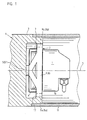
- An angle measuring device 1 shown in FIG. 1 is via a clutch 2 with the stator 3 of a drive device 4 connected.
- the shaft 5 of the angle measuring device 1 is rigid with the shaft 5 'of the Drive device 4 coupled. Free ends of axially parallel leaf spring arms 6 and 7 are by means of Screws that are visible in Figure 4 with the Stator 10 of the angle measuring device 1 connected.
- On Housing 11 encloses the drive device 4 and the angle measuring device 1.
- the stator 3 Drive device 4 is, for example, the stationary one Part of an engine.
- the stator 10 of the angle measuring device 1 is a stationary part of the angle measuring device, for example a mounting flange, the scanner or the housing of the Angle measuring device.
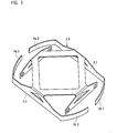
- the clutch 2 shown in Figures 2 and 3 is integrally formed as a stamped and bent part and made of a material with high fatigue strength, e.g. Spring steel, manufactured.
- the clutch 2 has a flat central area with four essentially Leaf spring arms running parallel to the axis of rotation D. 6, 7; 8, 9, of which two (6 and 7 or 8 and 9) arranged diametrically opposite are.
- the leaf spring arms 6, 7, 8, 9 are at least largely parallel to the common axis of rotation D of parts 1 and 4 to be aligned.
- she are diametrically opposed and parallel in pairs arranged to each other and thus form two spring parallelograms arranged perpendicular to each other, which is a torsionally rigid but radially flexible Ensure connection of the two parts 1 and 4.
- the clutch 2 has a central one in the central region Opening 12 on that in the manner of a truss surrounded by further leaf spring arms 13, 14, 15, 16 is. Ensure these leaf spring arms 13, 14, 15, 16 a torsionally rigid, but axially in the direction the axis of rotation D compliant connection of two parts 1 and 4.
- Leaf spring arms 6, 7, 8, 9 are advantageous also half-timbered, but as triangles trained so that from the shafts 5, 5 'to the Angle measuring device 1 acting torques well be recorded and not to a twist both stators 3 and 10 leads.
- two of these opposite leaf spring arms 6, 7 are two elongated holes 19 whose longitudinal axes parallel to the axis of rotation D run.
- the elongated holes 19 allow adjustment between the two parts 3, 10 to be coupled when fastening to the angle measuring device by means of screws 1.
- the other two opposite leaf spring arms 8 and 9 point - as an extension of their Base - almost circularly curved leaf spring arms 8a, 8b; 9a, 9b.
- These leaf spring arms 8a, 8b; 9a, 9b are radially biased so that they are Inserting into a tube 17 on the drive device 4 is intended to be compressed have to. After insertion into the tube 17 spread the leaf spring arms 8a, 8b; 9a, 9b and due to the radial outward portion the spreading force becomes the angle measuring device 1 in the drive unit 4 fixed against rotation.
- the radial and axial compensation movements and angular misalignment are easily compensated.
- leaf spring arms 8a, 8b; 9a, 9b on their free ends are bent radially inwards - like is shown in Figure 2, the Leaf spring arms 8a, 8b; 9a, 9b also with the help of screws or the like, not shown spread to the contact pressure on the inner jacket of the to increase cylindrical tube 17.
- Figure 2 is the tube 17 with a colon / dash line indicated.
- the framework-like training shown in Figure 2 the leaf spring arms 6, 7, 8, 9 and 13, 14, 15, 16 is not absolutely necessary for the invention.
- the leaf spring arms can for example also according to DE-89 15 109-U1 or DE-88 12 317-U1 designed and arranged.
- Essential is that the clutch 2 is torsionally stiff and only axial and radial movements the two parts 3 and 10 to be connected allows.
- a coupling in the form of two vertical is arranged parallel to each other spring parallelograms particularly advantageous.
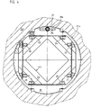
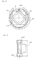
- FIG 4 is a plan view of a clutch 2.4 shown with a mounting element 18. Screw 29, 20, 21, 22 are used to attach the clutch 2.4 on the angle measuring device, not shown, as has already been indicated for Figure 1.
- the Mounting element 18 is designed as a ring element, which is essentially circular. about further screws 23, 24, 25, 26 is the coupling 2.4 connected to this annular mounting member 18.
- the stator 3.4 Drive unit 4 a tube 17.4, the one certain inner diameter, which on the Outside diameter of the mounting element 18 matched is.
- the pre-assembled unit angle measuring device / mounting element is inserted into the tube 17.4 and the mounting element 18 is by means of a clamping element trained expansion body 18a in the tube 17.4 fixed.
- the Spreading body 18a configured as a segment of a circle, which by a detachable portion of the mounting element 18 is formed.
- the circular segment 18a has on its outer circumference plan the mounting element 18 facing away Section surface on a conical partial bore 18b.
- the mounting element 18 points to one of the plans Section surface of the circular segment 18a opposite, surface 18c also plans one conical partial bore 18d, which with the partial bore 18b of the circular segment 18a corresponds.
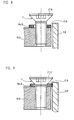
- Figure 5 is a cross section through the device shown in Figure 4. Be particularly clear here the conical screw 27 and the same conical partial bores 18b, 18d in the mounting element 18 and the circular segment 18a.
- the tube 17.4 the drive unit is with colon / dash lines shown.
- the expansion body is part of the mounting element itself by this part, for example, via a vulnerability is connected to the mounting element and via a Actuator - for example a screw - radially against a radially extending interior or The outer surface can be pressed on.
- the mounting element is designed so stable that the counterforce of the Actuator picks up, so that only the expansion body deformed and none Force acts on the clutch.
- FIG 6 is a plan view of another embodiment presented the invention.
- the scanning unit is not Angle measuring device shown on the clutch 2.6 radially and axially compliant with the stator 3.6 coupled to a drive device.
- the clutch 2.6 is also here provided with an annular mounting element 18.6.
- a clamping element in the form of a Eccentric screw 18a.6 provided.
- the head of this Eccentric screw 18a.6 has an eccentric Circumferential surface U by turning with the tube 17.6 comes into contact and a radial Clamping force between the mounting element 18.6 and the Stator 3.6 causes.
- the mounting element 18.6 in the example shown with the stop surfaces 30 pressed an inner wall of the tube 17.6.
- Figure 7 is a schematic cross section of the device shown in Figure 6.
- FIG radial clamping of a mounting element 18.8 schematically shown.
- a countersunk screw 27.8 as an actuator used.
- the conical surface F of the countersunk screw 27.8 acts when screwed into the mounting element 18.8 on a washer 18a.8 and move it radially outward, as in Figure 9 can be seen.
- the washer is 18a.8 thus the clamping element, which has a radial clamping of the mounting element 18.8 inside the tube 17.8 of the stator 3.8 causes.
- it can also be done with the countersunk screw 27.8 directly part of the mounting element 18.8 itself be deformed and cause the clamping.
- FIGS Embodiment Another is shown schematically in FIGS Embodiment shown.
- the coupling 2.10 for radial and axial compensation is on the annular mounting element 18.10 attached.
- this mounting element 18.10 is at least one radial extending slot 31 is provided.
- This Slot 31 divides the mounting element 18.10 in such a way that the outer diameter of the mounting element 18.10 by a clamping element acting in slot 31 18a.10 can be enlarged.
- This spreading of the mounting element 18.10 is done by two in axially spaced one behind the other Clamping elements 18a.10.
- These clamping elements 18a.10 have opposite conical surfaces on the corresponding surfaces of the Support assembly element 18a.10.
- One of these Clamping elements 18a.10 is one in the example shown Screw and the other a nut.
- the screw can also act as an actuator be designated. In a way not shown the screw can only move in the axial direction Support on a flat surface so that only the Nut serves as a clamping element.
- 11 is a cross section of the clamping element 18a.10 shown enlarged in slot 31.
- the clamp acts on an inner one Circumferential surface.
- This peripheral area is a surface that faces or points away from the axis of rotation.
- radial defines a direction that runs at least largely perpendicular to the axis of rotation D.
- the Possibility of all for mounting the clutch 2 on the Stator 3 required parts 18 within the overall length the clutch 2 and the angle measuring device 1 to arrange yourself.
Landscapes
- Physics & Mathematics (AREA)
- General Physics & Mathematics (AREA)
- Transmission And Conversion Of Sensor Element Output (AREA)
- A Measuring Device Byusing Mechanical Method (AREA)
- Body Structure For Vehicles (AREA)
- Vehicle Body Suspensions (AREA)
- Length Measuring Devices With Unspecified Measuring Means (AREA)
Claims (14)
- Dispositif de mesure d'angles (1) pour mesurer la position angulaire entre un objet stationnaire (3) et un objet (5, 5') pouvant tourner par rapport au premier, dans lequel une règle de mesure est palpée par une unité de palpage qui est liée par un moyen de couplage (2) de manière rigide en rotation mais souple dans les directions radiale et axiale à l'objet stationnaire, via un stator (10) du dispositif de mesure d'angles (1), par le fait que le moyen de couplage (2) est fixé d'un côté au stator (10) du dispositif de mesure d'angles (1) et de l'autre côté à une surface périphérique intérieure (17) de l'objet stationnaire (3), caractérisé en ce que la fixation à la surface périphérique intérieure (17) s'effectue par serrage entre le moyen de couplage (2) et l'objet stationnaire (3), contre la surface périphérique intérieure (17) de l'objet stationnaire (3), et en ce que, en vue du serrage, un élément de serrage (18a) est disposé pour produire une force de serrage radiale entre le moyen de couplage (2) et la surface périphérique (17).
- Dispositif de mesure d'angles selon la revendication 1, caractérisé en ce que l'élément de serrage (18a) est fixé à un élément de montage (18) et que l'élément de montage (18) est un corps annulaire placé entre l'objet stationnaire (3) et le moyen de couplage (2).
- Dispositif de mesure d'angles selon la revendication 1 ou 2, caractérisé en ce que l'élément de serrage (18a) peut être déplacé en translation, tourné ou déformé, afin d'obtenir un serrage radial entre l'élément de montage (18) et l'objet stationnaire (3).
- Dispositif selon la revendication 3, caractérisé en ce que l'élément de serrage (18a) permet de modifier le diamètre de l'élément de montage (18) et qu'une surface de l'élément de montage (18) peut être appliquée contre la surface périphérique (17) de l'objet stationnaire (3).
- Dispositif selon l'une quelconque des revendications précédentes 2 à 4, caractérisé en ce que l'élément de serrage (18a) et/ou un élément d'actionnement (27) présente une surface (18b, 18d, F), s'étendant en biais par rapport à l'axe de rotation (D), et en ce que le déplacement axial de l'élément d'actionnement (27) a pour effet de déplacer l'élément de serrage (18a) dans la direction radiale et/ou de modifier le diamètre de l'élément de montage (18).
- Dispositif selon la revendication 5, caractérisé en ce que l'élément d'actionnement (27) est une vis présentant une surface (F) conique.
- Dispositif selon la revendication 3, caractérisé en ce que l'élément de serrage (18a) présente une surface excentrique (U) et est disposé dans l'élément de montage (18) avec possibilité de rotation autour d'un axe parallèle à l'axe de rotation (D), la surface excentrique (U) provoquant un serrage radial.
- Dispositif selon la revendication 7, caractérisé en ce que la surface excentrique (U) de l'élément de serrage (18a) tournant peut être amenée en contact avec une surface (17) de l'objet stationnaire (3).
- Dispositif selon l'une quelconque des revendications précédentes, caractérisé en ce que le moyen de couplage (2) se compose de deux parallélogrammes (6, 7; 8, 9) disposés de façon orthogonale.
- Dispositif selon la revendication 9, caractérisé en ce que chaque parallélogramme (6, 7; 8, 9) est constitué de lames de ressort mutuellement parallèles et qu'au moins les lames de ressort (8, 9) d'un parallélogramme comportent des éléments de serrage (8a, 8b; 9a, 9b) en vue du serrage radial sur l'objet stationnaire.
- Dispositif selon l'une quelconque des revendications précédentes, caractérisé en ce que l'objet stationnaire (3) comprend un tube de montage (17) dont la surface enveloppe intérieure est destinée à assurer le serrage radial du moyen de couplage (2).
- Dispositif selon la revendication 11, caractérisé en ce que l'élément de serrage (18a) ou un élément d'actionnement (27) coopérant avec l'élément de serrage (18a) est accessible et actionnable parallèlement à l'axe de rotation (D).
- Dispositif selon la revendication 11 ou 12, caractérisé en ce que le tube de montage (17) fait partie intégrante d'un moteur (4).
- Dispositif selon l'une quelconque des revendications précédentes, caractérisé en ce que le moyen de couplage (2) est fixé par serrage radial au stator (10) du dispositif de mesure d'angles (1).
Priority Applications (4)
| Application Number | Priority Date | Filing Date | Title |
|---|---|---|---|
| DE29623537U DE29623537U1 (de) | 1995-09-06 | 1996-07-23 | Winkelmeßeinrichtung |
| DE19629585A DE19629585C2 (de) | 1995-09-06 | 1996-07-23 | Winkelmeßeinrichtung |
| JP22693696A JP3148649B2 (ja) | 1995-09-06 | 1996-08-28 | 測角装置 |
| US08/707,652 US5758427A (en) | 1995-09-06 | 1996-09-05 | Angular-position measuring device having a mounting element for torsion-proof mounting of a stator to a stationary object |
Applications Claiming Priority (2)
| Application Number | Priority Date | Filing Date | Title |
|---|---|---|---|
| DE19532824 | 1995-09-06 | ||
| DE19532824 | 1995-09-06 |
Publications (2)
| Publication Number | Publication Date |
|---|---|
| EP0762082A1 EP0762082A1 (fr) | 1997-03-12 |
| EP0762082B1 true EP0762082B1 (fr) | 2004-03-17 |
Family
ID=7771363
Family Applications (1)
| Application Number | Title | Priority Date | Filing Date |
|---|---|---|---|
| EP95118933A Expired - Lifetime EP0762082B1 (fr) | 1995-09-06 | 1995-12-01 | Capteur de position angulaire |
Country Status (3)
| Country | Link |
|---|---|
| EP (1) | EP0762082B1 (fr) |
| AT (1) | ATE262161T1 (fr) |
| DE (1) | DE59510876D1 (fr) |
Families Citing this family (8)
| Publication number | Priority date | Publication date | Assignee | Title |
|---|---|---|---|---|
| DE19747356A1 (de) | 1997-10-27 | 1999-04-29 | Heidenhain Gmbh Dr Johannes | Längenmeßeinrichtung und Maschine mit einer Längenmeßeinrichtung |
| DE19836003A1 (de) | 1998-08-08 | 2000-02-10 | Heidenhain Gmbh Dr Johannes | Verfahren zur Montage einer Positionsmeßeinrichtung und Positioniermittel zur Montage |
| DE29911508U1 (de) | 1999-07-01 | 2000-12-07 | Dr. Johannes Heidenhain Gmbh, 83301 Traunreut | Kupplung und Verwendung dieser Kupplung in einer Winkelmeßeinrichtung |
| DE10063013B4 (de) * | 2000-12-16 | 2011-06-30 | Dr. Johannes Heidenhain GmbH, 83301 | Winkelmesseinrichtung |
| DE10219245B4 (de) | 2002-04-24 | 2008-10-30 | Dr. Johannes Heidenhain Gmbh | Verfahren zum Trennen einer Geberwelle eines Drehgebers von einer Antriebswelle |
| DE102008032419A1 (de) * | 2008-07-10 | 2010-01-14 | Dr. Johannes Heidenhain Gmbh | Drehgeber und Baureihe von Drehgebern |
| EP2216630B2 (fr) * | 2008-11-24 | 2015-09-30 | Pepperl + Fuchs Drehgeber GmbH | Support de couple |
| CN110906841A (zh) * | 2019-12-20 | 2020-03-24 | 上海索达传动机械有限公司 | 一种夹角测量工具 |
Family Cites Families (9)
| Publication number | Priority date | Publication date | Assignee | Title |
|---|---|---|---|---|
| DE2906432C2 (de) | 1979-02-20 | 1980-08-07 | Dr. Johannes Heidenhain Gmbh, 8225 Traunreut | Koppeleinrichtung |
| US4386270A (en) | 1981-06-08 | 1983-05-31 | Data Technology, Inc. | Angular information transducer mounting |
| US4472713A (en) * | 1981-11-06 | 1984-09-18 | Itek Corporation | Optical encoder with integral flexible coupler |
| DE3301205C2 (de) | 1982-02-26 | 1985-10-03 | Dr. Johannes Heidenhain Gmbh, 8225 Traunreut | Winkelmeßeinrichtung |
| DE3206875C2 (de) | 1982-02-26 | 1993-05-27 | Dr. Johannes Heidenhain Gmbh, 8225 Traunreut | Winkelmeßeinrichtung |
| JPS62155313U (fr) | 1986-03-26 | 1987-10-02 | ||
| US4794250A (en) * | 1987-02-27 | 1988-12-27 | Hewlett-Packard Company | Self-gapping optical encoder |
| DE8812317U1 (de) | 1988-09-29 | 1988-11-17 | Max Stegmann GmbH, Uhren- und Elektroapparatefabrik, 78166 Donaueschingen | Drehgeber |
| DE8915109U1 (de) | 1989-12-23 | 1990-02-22 | Dr. Johannes Heidenhain Gmbh, 83301 Traunreut | Kupplung |
-
1995
- 1995-12-01 EP EP95118933A patent/EP0762082B1/fr not_active Expired - Lifetime
- 1995-12-01 AT AT95118933T patent/ATE262161T1/de not_active IP Right Cessation
- 1995-12-01 DE DE59510876T patent/DE59510876D1/de not_active Expired - Lifetime
Also Published As
| Publication number | Publication date |
|---|---|
| DE59510876D1 (de) | 2004-04-22 |
| EP0762082A1 (fr) | 1997-03-12 |
| ATE262161T1 (de) | 2004-04-15 |
Similar Documents
| Publication | Publication Date | Title |
|---|---|---|
| DE19629585C2 (de) | Winkelmeßeinrichtung | |
| EP0164792B1 (fr) | Dispositif pour l'accouplement positif de deux arbres | |
| DE4337867A1 (de) | Differential-Linearaktuator | |
| WO2005053914A1 (fr) | Passage rotatif d'un bras de robot | |
| EP0762082B1 (fr) | Capteur de position angulaire | |
| DE69819826T2 (de) | Servosteuersystem | |
| DE10063013B4 (de) | Winkelmesseinrichtung | |
| DE4317364B4 (de) | Universalgelenk | |
| EP2096737B1 (fr) | Moteur submersible | |
| DE19506815A1 (de) | Homokinetisches Gelenk und dieses Gelenk verwendende Axialkolbenpumpe | |
| DE10161356A1 (de) | Schraubgerät | |
| DE102007008246B4 (de) | Vorrichtung zum Spannen des Riemens eines elektrischen Lenkungsantriebs | |
| EP2187097B1 (fr) | Entraînement linéaire | |
| EP0762081A1 (fr) | Capteur d'angle de rotation | |
| DE19729452C2 (de) | Adapterbauteil | |
| DE2402101A1 (de) | Einrichtung zum verbinden des formzylinders einer rotationsdruckmaschine mit dessen antriebswelle | |
| EP0075749B1 (fr) | Entraînement électrique compact biaxial, en particulier pour positionnement | |
| DE102021119521B4 (de) | Lagerungsanordnung einer Taumelscheibe auf einer Welle und chirurgisches Instrument | |
| DE102021119528B4 (de) | Lagerungsanordnung einer Taumelscheibe in einem Lenkgetriebebauteil und chirurgisches Instrument | |
| EP1517120B1 (fr) | Capteur de rotation | |
| LU101812B1 (de) | Ankoppelvorrichtung und Verfahren zum drehmomentübertragenden Ankoppeln einer Antriebsvorrichtung an ein Getriebe | |
| DE29623537U1 (de) | Winkelmeßeinrichtung | |
| DE102019215213B3 (de) | Gelenkvorrichtung | |
| EP0342260B1 (fr) | Accouplement flexible pour opération intermittente par exemple entraînement de commutateurs | |
| DE3419307A1 (de) | Anordnung zur loesbaren reibschlussverbindung zwischen einer als hohlwelle ausgebildeten getriebeeingangswelle und einer in diese einschiebbaren antriebswelle |
Legal Events
| Date | Code | Title | Description |
|---|---|---|---|
| PUAI | Public reference made under article 153(3) epc to a published international application that has entered the european phase |
Free format text: ORIGINAL CODE: 0009012 |
|
| 17P | Request for examination filed |
Effective date: 19961220 |
|
| AK | Designated contracting states |
Kind code of ref document: A1 Designated state(s): AT CH DE FR GB IT LI |
|
| 17Q | First examination report despatched |
Effective date: 19991201 |
|
| GRAP | Despatch of communication of intention to grant a patent |
Free format text: ORIGINAL CODE: EPIDOSNIGR1 |
|
| GRAS | Grant fee paid |
Free format text: ORIGINAL CODE: EPIDOSNIGR3 |
|
| GRAA | (expected) grant |
Free format text: ORIGINAL CODE: 0009210 |
|
| AK | Designated contracting states |
Kind code of ref document: B1 Designated state(s): AT CH DE FR GB IT LI |
|
| REG | Reference to a national code |
Ref country code: GB Ref legal event code: FG4D Free format text: NOT ENGLISH |
|
| REG | Reference to a national code |
Ref country code: CH Ref legal event code: NV Ref country code: CH Ref legal event code: EP |
|
| REF | Corresponds to: |
Ref document number: 59510876 Country of ref document: DE Date of ref document: 20040422 Kind code of ref document: P |
|
| GBT | Gb: translation of ep patent filed (gb section 77(6)(a)/1977) |
Effective date: 20040510 |
|
| ET | Fr: translation filed | ||
| PLBE | No opposition filed within time limit |
Free format text: ORIGINAL CODE: 0009261 |
|
| STAA | Information on the status of an ep patent application or granted ep patent |
Free format text: STATUS: NO OPPOSITION FILED WITHIN TIME LIMIT |
|
| 26N | No opposition filed |
Effective date: 20041220 |
|
| REG | Reference to a national code |
Ref country code: CH Ref legal event code: NV Representative=s name: TROESCH SCHEIDEGGER WERNER AG |
|
| PGFP | Annual fee paid to national office [announced via postgrant information from national office to epo] |
Ref country code: AT Payment date: 20091217 Year of fee payment: 15 |
|
| PGFP | Annual fee paid to national office [announced via postgrant information from national office to epo] |
Ref country code: GB Payment date: 20101221 Year of fee payment: 16 |
|
| PG25 | Lapsed in a contracting state [announced via postgrant information from national office to epo] |
Ref country code: AT Free format text: LAPSE BECAUSE OF NON-PAYMENT OF DUE FEES Effective date: 20101201 |
|
| PGFP | Annual fee paid to national office [announced via postgrant information from national office to epo] |
Ref country code: FR Payment date: 20120105 Year of fee payment: 17 |
|
| PGFP | Annual fee paid to national office [announced via postgrant information from national office to epo] |
Ref country code: IT Payment date: 20111229 Year of fee payment: 17 |
|
| GBPC | Gb: european patent ceased through non-payment of renewal fee |
Effective date: 20121201 |
|
| REG | Reference to a national code |
Ref country code: FR Ref legal event code: ST Effective date: 20130830 |
|
| PG25 | Lapsed in a contracting state [announced via postgrant information from national office to epo] |
Ref country code: GB Free format text: LAPSE BECAUSE OF NON-PAYMENT OF DUE FEES Effective date: 20121201 Ref country code: FR Free format text: LAPSE BECAUSE OF NON-PAYMENT OF DUE FEES Effective date: 20130102 |
|
| PG25 | Lapsed in a contracting state [announced via postgrant information from national office to epo] |
Ref country code: IT Free format text: LAPSE BECAUSE OF NON-PAYMENT OF DUE FEES Effective date: 20121201 |
|
| PGFP | Annual fee paid to national office [announced via postgrant information from national office to epo] |
Ref country code: CH Payment date: 20131219 Year of fee payment: 19 |
|
| PGFP | Annual fee paid to national office [announced via postgrant information from national office to epo] |
Ref country code: DE Payment date: 20141211 Year of fee payment: 20 |
|
| REG | Reference to a national code |
Ref country code: CH Ref legal event code: PL |
|
| PG25 | Lapsed in a contracting state [announced via postgrant information from national office to epo] |
Ref country code: CH Free format text: LAPSE BECAUSE OF NON-PAYMENT OF DUE FEES Effective date: 20141231 Ref country code: LI Free format text: LAPSE BECAUSE OF NON-PAYMENT OF DUE FEES Effective date: 20141231 |
|
| REG | Reference to a national code |
Ref country code: DE Ref legal event code: R071 Ref document number: 59510876 Country of ref document: DE |