EP0762021B1 - Lippendichtring - Google Patents
Lippendichtring Download PDFInfo
- Publication number
- EP0762021B1 EP0762021B1 EP96110879A EP96110879A EP0762021B1 EP 0762021 B1 EP0762021 B1 EP 0762021B1 EP 96110879 A EP96110879 A EP 96110879A EP 96110879 A EP96110879 A EP 96110879A EP 0762021 B1 EP0762021 B1 EP 0762021B1
- Authority
- EP
- European Patent Office
- Prior art keywords
- sealing
- lip
- lip seal
- swirl
- machine part
- Prior art date
- Legal status (The legal status is an assumption and is not a legal conclusion. Google has not performed a legal analysis and makes no representation as to the accuracy of the status listed.)
- Expired - Lifetime
Links
- 238000007789 sealing Methods 0.000 claims description 64
- 239000004810 polytetrafluoroethylene Substances 0.000 claims description 5
- 229920001343 polytetrafluoroethylene Polymers 0.000 claims description 5
- 239000000463 material Substances 0.000 claims description 2
- 230000001154 acute effect Effects 0.000 claims 1
- 230000000149 penetrating effect Effects 0.000 claims 1
- 230000002787 reinforcement Effects 0.000 claims 1
- 239000001993 wax Substances 0.000 description 22
- 238000009434 installation Methods 0.000 description 9
- 238000012360 testing method Methods 0.000 description 9
- 238000011144 upstream manufacturing Methods 0.000 description 4
- VBICKXHEKHSIBG-UHFFFAOYSA-N 1-monostearoylglycerol Chemical compound CCCCCCCCCCCCCCCCCC(=O)OCC(O)CO VBICKXHEKHSIBG-UHFFFAOYSA-N 0.000 description 3
- DCXXMTOCNZCJGO-UHFFFAOYSA-N Glycerol trioctadecanoate Natural products CCCCCCCCCCCCCCCCCC(=O)OCC(OC(=O)CCCCCCCCCCCCCCCCC)COC(=O)CCCCCCCCCCCCCCCCC DCXXMTOCNZCJGO-UHFFFAOYSA-N 0.000 description 3
- 230000000694 effects Effects 0.000 description 3
- 239000012530 fluid Substances 0.000 description 3
- 230000002411 adverse Effects 0.000 description 2
- 238000002844 melting Methods 0.000 description 2
- 230000008018 melting Effects 0.000 description 2
- 230000006978 adaptation Effects 0.000 description 1
- 238000004026 adhesive bonding Methods 0.000 description 1
- 230000032683 aging Effects 0.000 description 1
- 238000002485 combustion reaction Methods 0.000 description 1
- 239000000428 dust Substances 0.000 description 1
- 230000005489 elastic deformation Effects 0.000 description 1
- 238000007689 inspection Methods 0.000 description 1
- 239000007788 liquid Substances 0.000 description 1
- 230000001050 lubricating effect Effects 0.000 description 1
- 239000010687 lubricating oil Substances 0.000 description 1
- 230000007257 malfunction Effects 0.000 description 1
- 238000004519 manufacturing process Methods 0.000 description 1
- 239000007769 metal material Substances 0.000 description 1
- 239000003921 oil Substances 0.000 description 1
- 239000012188 paraffin wax Substances 0.000 description 1
- 230000002093 peripheral effect Effects 0.000 description 1
- 239000002861 polymer material Substances 0.000 description 1
- 239000003566 sealing material Substances 0.000 description 1
- 238000003860 storage Methods 0.000 description 1
- 230000007704 transition Effects 0.000 description 1
- 238000004018 waxing Methods 0.000 description 1
Images
Classifications
-
- F—MECHANICAL ENGINEERING; LIGHTING; HEATING; WEAPONS; BLASTING
- F16—ENGINEERING ELEMENTS AND UNITS; GENERAL MEASURES FOR PRODUCING AND MAINTAINING EFFECTIVE FUNCTIONING OF MACHINES OR INSTALLATIONS; THERMAL INSULATION IN GENERAL
- F16J—PISTONS; CYLINDERS; SEALINGS
- F16J15/00—Sealings
- F16J15/16—Sealings between relatively-moving surfaces
- F16J15/32—Sealings between relatively-moving surfaces with elastic sealings, e.g. O-rings
- F16J15/3204—Sealings between relatively-moving surfaces with elastic sealings, e.g. O-rings with at least one lip
- F16J15/3228—Sealings between relatively-moving surfaces with elastic sealings, e.g. O-rings with at least one lip formed by deforming a flat ring
-
- F—MECHANICAL ENGINEERING; LIGHTING; HEATING; WEAPONS; BLASTING
- F16—ENGINEERING ELEMENTS AND UNITS; GENERAL MEASURES FOR PRODUCING AND MAINTAINING EFFECTIVE FUNCTIONING OF MACHINES OR INSTALLATIONS; THERMAL INSULATION IN GENERAL
- F16J—PISTONS; CYLINDERS; SEALINGS
- F16J15/00—Sealings
- F16J15/16—Sealings between relatively-moving surfaces
- F16J15/32—Sealings between relatively-moving surfaces with elastic sealings, e.g. O-rings
- F16J15/3244—Sealings between relatively-moving surfaces with elastic sealings, e.g. O-rings with hydrodynamic pumping action
-
- F—MECHANICAL ENGINEERING; LIGHTING; HEATING; WEAPONS; BLASTING
- F05—INDEXING SCHEMES RELATING TO ENGINES OR PUMPS IN VARIOUS SUBCLASSES OF CLASSES F01-F04
- F05C—INDEXING SCHEME RELATING TO MATERIALS, MATERIAL PROPERTIES OR MATERIAL CHARACTERISTICS FOR MACHINES, ENGINES OR PUMPS OTHER THAN NON-POSITIVE-DISPLACEMENT MACHINES OR ENGINES
- F05C2225/00—Synthetic polymers, e.g. plastics; Rubber
- F05C2225/04—PTFE [PolyTetraFluorEthylene]
Definitions
- Lip sealing ring for a relatively movable machine part comprising a flexible Sealing lip made of polymer material, which the machine part in the area of a Sealing gap touched under an elastic bias, the Sealing gap at at least one circumferential point of a swirl step in the longitudinal direction is penetrated that the axis of the machine part under a pointed Angle is assigned.
- Such a sealing ring is known from US Pat. No. 3,985,487. It is for sealing determines a shaft rotating about an axis and has a sealing lip based on a circular disc with plane-parallel surfaces is generated, made of PTFE and in the area of its inner circumference in axial Direction according to the type of bell a trumpet is bulging.
- the bulging Section shows during intended use in Direction of the space to be sealed. Its inside touches the surface the shaft to be sealed under an elastic prestress. She is with one provided helical helical swirl step, which is part of a Swirl groove forms.
- a rotationally symmetrical shaft results in a swirl groove Gap that connects the space to be sealed with the environment and the Purpose is to leak fluid passing through the sealing gap while rotating To return the resulting hydrodynamic forces into the sealed space.
- the swirl stage closes with the axis of the shaft An angle that is inclined so that case drain liquid when the shaft rotates Is thrown back towards the sealed room.
- the well-known lip seal is used in many cases using automatic Assembly facilities assembled. It can happen that the sealing lip is turned over by unpredictable influences and in the area of your Inner circumference does not point towards the space to be sealed, as prescribed, but towards the environment. In this way, no one can achieve a satisfactory sealing result. It is therefore necessary to everyone check the individual lip sealing ring after its assembly, whether or not the lip ring points towards the space to be sealed. Especially in installation positions where the installation site is difficult to see is difficult to do manually. It is therefore common to use the sealed one Space following the assembly of the lip seal with compressed air predetermined control pressure and the pressure drop during a certain Period of time to watch. If there is a very rapid drop in pressure, So this is a sure sign that the sealing lip is loose during installation of the lip seal ring and at least not the prescribed one Assignment to the surface of the shaft to be sealed.
- the invention has for its object one with at least one swirl stage Provide provided lip seal so that one after installation present, faulty installation position using the pressure test can be recognized.
- the gap which results in the area of the swirl step after the lip seal has been installed, is sealed with wax in the area of the sealing gap.
- the gaps formed by the swirl steps in the area of the sealing gap can a very small cross-section of a few hundredths of a square millimeter to have.
- the amount of wax needed to close the sealing gap can accordingly be small. It can be overdosed without that malfunctions are to be expected.
- Waxes generally have a melting point between 50 and 90 °.
- the gaps that exist in the area of the twist steps between one Lip ring and a wave can easily be completely waxed close, i.e. to such an extent that there is an inner contour that an imaginary cylinder surface or at least a rotationally symmetrical one Surface largely corresponds. Such a surface is capable of being sealed To nestle the shaft without any problems.
- the permanent deformability waxing is of great importance for this.
- Waxes adhere sufficiently to all common, polymeric sealing materials firm for carrying out the pressure test.
- the use of paraffin or stearin wax is preferred in the context of the present invention.
- the melting temperature is about 55 ° C. She will be at the rotating shaft under normal conditions resulting friction heat in the area reached and exceeded the sealing gap, with the result that the Wax liquefied and by itself during the intended use resulting hydrodynamic effects removed from the sealing gap and is promoted in the direction of the space to be sealed. It's headed for it make sure that the medium to be sealed and the wax are in such a way are coordinated that the performance characteristics of the medium to be sealed not be adversely affected after mixing with the wax. The Twist level is then free of wax and fully effective.
- the invention can be applied to swirl stages of any type touch the sealing gap in any way.
- the swirl stages can, for example in the sealing lip and / or the machine part, for example one around them Axis rotatable shaft, attached and for example a component of twist grooves.
- swirl stages can be provided limit the overlapping swirl ribs or swirl grooves as well Versions that limit cup-shaped recesses. Is important in all cases that at least one baffle in the circumferential direction of the sealing lip is present, which is the drag flow carried by the rotating shaft redirected towards the sealed room.
- Such an impact surface sets one step-like interruption of the otherwise annular sealing lip ahead, i.e. a spin level. This deviation from the intended continuation the circular shape causes the leakage when pressure testing a seal, which does not have the features of the embodiment according to the invention. she will in the sense of the invention compensated by the temporary in the range of the deviation applied wax.
- Waxes already have a dough-like shape at a temperature of approx. 20 ° C Consistency. It is therefore not necessary for the purposes of the invention Apply the wax to be applied particularly finely or subsequently in the area smooth the surface.
- Waxes also have the advantage of not chemically aging or theirs Consistency during the storage of a sealing ring at room temperature change that the sealing of a sealing gap after the proper Installation of a sealing ring is no longer successful. Your application is so far very easy.
- Waxes do not mix with an adverse change in the lubricating properties with oil. You can choose from a standard filter Lubricating oil to be excreted.
- the swirl stage or the swirl stages can follow the machine part to be sealed kind of a helix or of circular segments at least partially in the circumferential direction enclose.
- the sealing lip is made of PTFE
- the reason for this is likely consists in that, unlike rubber, PTFE is a material deals with a horny consistency that is so tough that the the swirl stages touching the surface of a shaft to be sealed are not without difficulty be deformed so largely that the upstream gaps through the elastic deformations are closed, resulting from the usual contact pressure
- Such a sealing lip on a machine part to be sealed result.
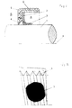
- the lip seal shown in Fig. 1 in half section is intended for a relatively movable machine part, for example for a crankshaft of an internal combustion engine rotating about an axis.
- the Lip sealing ring includes a flexible sealing lip, which is part of an annular Disc with plane-parallel surfaces that is made of PTFE consists.
- the disc is shaped like a trumpet's bell and in the range of their smallest diameter during the intended Use preferred in the direction of the space to be sealed. It touches with this area also the surface of the crankshaft to be sealed.
- the largest diameter of the circular disc is on a stiffening ring 8 made of metallic material, for example by gluing, Vulcanizing or pinching.
- the stiffening ring 8 is partially embedded in a sheath 5 made of rubber which the surface of the crankshaft 1 to be sealed on the outside air facing side with a circumferential dust lip 6 touches.
- the Sealing lip 2 is in the area of the sealing gap with a crankshaft to be sealed on its entire outer circumference, screw-shaped Provide swirl stage 3, which limits a swirl groove. This closes, in Considered circumferential direction, with the axis 4 of the crankshaft 1 a pointed Angle on.
- the direction of inclination of the swirl stage 3 is set so that at rotating crankshaft 1 in the region of the swirl stage 3 a conveying effect in Direction of the space to be sealed A results. Leakage fluid covering the sealing gap happens when the crankshaft 1 is stationary in the direction of the outside B, is thereby when the crankshaft 1 starts rotating again promoted room A to be sealed.
- the swirl step on one only peripheral point 4 (FIG. 2) is closed by wax 7, for example stearin. It goes without saying that the wax on one Place in the swirl stage which is located in the sealing gap, and that the amount must completely fill the free cross section of the groove. The The amount of wax 7 should be measured so that the Sealing gap through the wax 7 is completely closed.
Landscapes
- Engineering & Computer Science (AREA)
- General Engineering & Computer Science (AREA)
- Mechanical Engineering (AREA)
- Physics & Mathematics (AREA)
- Fluid Mechanics (AREA)
- Sealing With Elastic Sealing Lips (AREA)
Description
- Fig. 1
- ein Lippendichtring der erfindungsgemäßen Art in einer geschnittenen Darstellung.
- Fig. 2
- einen Ausschnitt aus der Dichtlippe des Lippendichtrings gemäß Fig. 1 in vergrößerter Darstellung.
Claims (6)
- Lippendichtring für ein relativ bewegbares Maschinenteil (1), umfassend eine flexible Dichtlippe (2) aus polymerem Werkstoff, die den Maschinenteil (1) im Bereich eines Dichtspalts unter einer elastischen Vorspannung anliegend berührt, wobei der Dichtspalt an zumindest einer Umfangsstelle von einer Drallstufe (3) in Längsrichtung durchdrungen ist, die der Achse (4) des Maschinenteils (1) unter einem spitzen Winkel zugeordnet ist und der eine Lücke vorgelagert ist, dadurch gekennzeichnet, daß der Dichtspalt zumindest im Bereich der der Drallstufe (3) vorgelagerten Lücke durch Wachs (7) verschlossen ist.
- Lippendichtring nach Anspruch 1, dadurch gekennzeichnet, daß die Drallstufe (3) eine dem Maschinenteil (1) zugewandte Dichtfläche der Dichtlippe (2) unterbricht.
- Lippendichtring nach Anspruch 1 bis 2, dadurch gekennzeichnet, daß die Drallstufe (3) das Maschinenteil (1) nach Art einer Helix zumindest teilweise in Umfangsrichtung umschließt.
- Lippendichtring nach Anspruch 2 bis 3, dadurch gekennzeichnet, daß die Dichtlippe (2) aus PTFE besteht.
- Lippendichtring nach Anspruch 4, dadurch gekennzeichnet, daß die Dichtlippe (2) nach Art des Schalltrichters einer Trompete gestaltet ist, der im Bereich seines kleinsten Durchmessers den relativ bewegbaren Maschinenteil (1) anliegend berührt und der im Bereich seines größten Durchmessers an einem Versteifungsring (8) festgelegt ist.
- Lippendichtring nach Anspruch 1 bis 5, dadurch gekennzeichnet, daß die Drallstufe (3) einen Bestandteil einer Drallnut bildet.
Applications Claiming Priority (2)
| Application Number | Priority Date | Filing Date | Title |
|---|---|---|---|
| DE19532701 | 1995-09-05 | ||
| DE19532701A DE19532701C2 (de) | 1995-09-05 | 1995-09-05 | Lippendichtring |
Publications (2)
| Publication Number | Publication Date |
|---|---|
| EP0762021A1 EP0762021A1 (de) | 1997-03-12 |
| EP0762021B1 true EP0762021B1 (de) | 1999-12-22 |
Family
ID=7771284
Family Applications (1)
| Application Number | Title | Priority Date | Filing Date |
|---|---|---|---|
| EP96110879A Expired - Lifetime EP0762021B1 (de) | 1995-09-05 | 1996-07-05 | Lippendichtring |
Country Status (4)
| Country | Link |
|---|---|
| US (1) | US5755444A (de) |
| EP (1) | EP0762021B1 (de) |
| BR (1) | BR9603652A (de) |
| DE (2) | DE19532701C2 (de) |
Cited By (1)
| Publication number | Priority date | Publication date | Assignee | Title |
|---|---|---|---|---|
| CN104500747A (zh) * | 2014-11-21 | 2015-04-08 | 广西智通节能环保科技有限公司 | 硅胶填料u型弹簧密封圈 |
Families Citing this family (16)
| Publication number | Priority date | Publication date | Assignee | Title |
|---|---|---|---|---|
| DE19733554A1 (de) * | 1997-08-02 | 1999-02-18 | Freudenberg Carl Fa | Radialwellendichtring |
| EP0999388A1 (de) * | 1998-11-05 | 2000-05-10 | Ford Global Technologies, Inc., A subsidiary of Ford Motor Company | PTFE Manschetten-Wellendichtung |
| US6257587B1 (en) * | 1999-05-21 | 2001-07-10 | Federal-Mogul World Wide, Inc. | Radial lip seal having protected porous dust excluder |
| DE10000853A1 (de) | 2000-01-12 | 2001-08-02 | Freudenberg Carl Fa | Dichtungsanordnung |
| US6471472B1 (en) * | 2000-05-03 | 2002-10-29 | Siemens Canada Limited | Turbomachine shroud fibrous tip seal |
| DE10024026A1 (de) * | 2000-05-16 | 2001-11-29 | Freudenberg Carl Fa | Dichtmanschette, insbesondere für Einbauräume mit kleinen Abmessungen |
| DE10063970B4 (de) * | 2000-12-20 | 2004-11-25 | Carl Freudenberg Kg | Lippendichtring |
| US6921082B2 (en) * | 2002-07-12 | 2005-07-26 | Carl Freudenberg Kg | Lip sealing ring |
| DE10128776A1 (de) * | 2001-06-13 | 2003-01-23 | Freudenberg Carl Kg | Lippendichtring |
| BRPI0402110A (pt) * | 2004-05-28 | 2005-02-15 | Sabo Ind & Comercio Ltda | Aperfeiçoamento em dispositivo de vedação de ptfe |
| DE102005024533B4 (de) * | 2005-05-28 | 2014-08-07 | Ab Skf | Lippendichtung mit einer temporären Beschichtung (Polymer) |
| DE102005024535B4 (de) * | 2005-05-28 | 2014-09-04 | Ab Skf | Temporäre Beschichtung für eine Lippendichtung(-Latex) |
| DE102005024530B4 (de) | 2005-05-28 | 2014-08-21 | Ab Skf | Lippendichtung mit einer temporären Beschichtung (Fett) |
| WO2018058068A1 (en) * | 2016-09-23 | 2018-03-29 | Federal-Mogul Powertrain Llc | Radial shaft seal assembly with debris exclusion member and method of construction thereof |
| IT201800008012A1 (it) | 2018-08-09 | 2020-02-09 | Truma Geraetetechnik Gmbh & Co Kg | Dispositivo di sicurezza per un dispositivo di conduzione del gas |
| IT201800008014A1 (it) | 2018-08-09 | 2020-02-09 | Truma Geraetetechnik Gmbh & Co Kg | Regolatore di pressione di gas |
Family Cites Families (20)
| Publication number | Priority date | Publication date | Assignee | Title |
|---|---|---|---|---|
| US2488465A (en) * | 1946-02-18 | 1949-11-15 | Jr Edmund W Bourne | Shaft seal |
| US2804325A (en) * | 1954-07-16 | 1957-08-27 | Gen Motors Corp | Fluid seal |
| GB1404760A (en) * | 1971-11-12 | 1975-09-03 | Angus George Co Ltd | Shaft seals |
| US3929341A (en) * | 1973-12-19 | 1975-12-30 | Federal Mogul Corp | Method of making polytetrafluoroethylene sealing elements with hydrodynamic action |
| US3941393A (en) * | 1974-03-15 | 1976-03-02 | Garlock Inc. | Seal method and article |
| US3985487A (en) * | 1974-11-13 | 1976-10-12 | Federal-Mogul Corporation | Apparatus for making polytetrafluoroethylene sealing elements with hydrodynamic action |
| US4038359A (en) * | 1975-01-27 | 1977-07-26 | Garlock Inc. | Method of making a shaft seal with dual lip |
| US4230157A (en) * | 1978-02-03 | 1980-10-28 | Wavin B.V. | Pipe having an end portion, the inner wall of which is provided with a circumferential groove, in which a sealing means is mounted and a pipe joint consisting of this pipe and a spigot end of a second pipe inserted therein |
| GB2096246B (en) * | 1981-04-07 | 1984-10-24 | Fenner Co Ltd J H | Seals |
| US4542573A (en) * | 1984-09-28 | 1985-09-24 | The Fluorocarbon Company | Method of producing a hydrodynamic seal |
| JPS61157877A (ja) * | 1984-12-28 | 1986-07-17 | Dainichi Nippon Cables Ltd | 摺動用パツキン |
| GB2173264B (en) * | 1985-04-04 | 1988-04-27 | Aeroquip International Inc | Ptfe sealing element for shaft seals |
| JPH06103069B2 (ja) * | 1986-02-15 | 1994-12-14 | エヌオーケー株式会社 | オイルシールの製造方法 |
| DE8705293U1 (de) * | 1987-04-09 | 1987-07-09 | SKF Gleitlager GmbH, 6625 Püttlingen | Vorrichtung zur Abdichtung von Lagern, insbesondere von Gelenklagern |
| US5015001A (en) * | 1990-07-23 | 1991-05-14 | Mather Seal Company | Low friction seal assembly |
| US5265890A (en) * | 1990-12-03 | 1993-11-30 | Peter J. Balsells | Seal with spring energizer |
| GB2258275B (en) * | 1991-07-27 | 1995-04-19 | Dowty Seals Ltd | A shaft seal |
| DE4307964C2 (de) * | 1993-03-12 | 1996-02-01 | Bruss Dichtungstechnik | Radial-Wellendichtring |
| FR2706565B1 (fr) * | 1993-06-14 | 1995-09-01 | Piv Sa | Joint d'étanchéité pour arbre tournant. |
| DE4324529C1 (de) * | 1993-07-21 | 1994-11-17 | Bruss Dichtungstechnik | Wellendichtring |
-
1995
- 1995-09-05 DE DE19532701A patent/DE19532701C2/de not_active Expired - Lifetime
-
1996
- 1996-07-05 EP EP96110879A patent/EP0762021B1/de not_active Expired - Lifetime
- 1996-07-05 DE DE59603965T patent/DE59603965D1/de not_active Expired - Lifetime
- 1996-09-04 BR BR9603652A patent/BR9603652A/pt not_active IP Right Cessation
- 1996-09-05 US US08/711,734 patent/US5755444A/en not_active Expired - Fee Related
Cited By (1)
| Publication number | Priority date | Publication date | Assignee | Title |
|---|---|---|---|---|
| CN104500747A (zh) * | 2014-11-21 | 2015-04-08 | 广西智通节能环保科技有限公司 | 硅胶填料u型弹簧密封圈 |
Also Published As
| Publication number | Publication date |
|---|---|
| BR9603652A (pt) | 1998-05-19 |
| DE59603965D1 (de) | 2000-01-27 |
| US5755444A (en) | 1998-05-26 |
| DE19532701A1 (de) | 1997-03-06 |
| DE19532701C2 (de) | 2000-01-05 |
| EP0762021A1 (de) | 1997-03-12 |
Similar Documents
| Publication | Publication Date | Title |
|---|---|---|
| DE19532701C2 (de) | Lippendichtring | |
| DE102007036625B4 (de) | Dichtelement | |
| DE2529509C2 (de) | ||
| EP1156241B1 (de) | Dichtmanschette, insbesondere für Einbauräume mit kleinen Abmessungen | |
| DE2460182C2 (de) | Drehklappenventil | |
| EP0814288B1 (de) | Vorrichtung zur Abdichtung eines Ringspaltes zwischen einem Gehäuse und einer Welle | |
| DE4125183C2 (de) | Kassettendichtung | |
| DE2534316A1 (de) | Ventildichtung fuer ein absperrventil | |
| DE19914921C2 (de) | Dichtring | |
| DE69017285T2 (de) | Kegelstumpfförmiges Ventilschaft-Dichtungselement. | |
| EP1387114A2 (de) | Manschettendichtung | |
| EP0266479B1 (de) | Torsionsschwingungsdämpfer mit integriertem Schrumpfring | |
| DE4022558A1 (de) | Dichtungsvorrichtungen fuer durchflussoeffnungen | |
| DE10033446A1 (de) | Wellendichtring | |
| DE2350630A1 (de) | Hydrodynamische wellendichtung | |
| DE69932156T2 (de) | Filterpatrone für Kraftstoff | |
| EP0331793B1 (de) | Dichtung für eine magnetisierbare Welle | |
| DE2759091C2 (de) | Vorrichtung zum Regulieren eines Gasdurchflusses | |
| EP0798498B1 (de) | Radialwellendichtring mit drehrichtungsunabhängiger Förderwirkung | |
| DE202019101183U1 (de) | Druckreduzierventil | |
| DE3244209A1 (de) | Dichtung zum abdichten gegen hydraulische medien, vorzugsweise dichtabstreifelement | |
| DE2608202A1 (de) | Korrosionsbestaendiges rohrleitungsventil fuer den betrieb mit aggressiven medien | |
| DE3501066C2 (de) | ||
| DE10000853A1 (de) | Dichtungsanordnung | |
| DE10143469B4 (de) | Dichtung |
Legal Events
| Date | Code | Title | Description |
|---|---|---|---|
| PUAI | Public reference made under article 153(3) epc to a published international application that has entered the european phase |
Free format text: ORIGINAL CODE: 0009012 |
|
| AK | Designated contracting states |
Kind code of ref document: A1 Designated state(s): DE FR GB IT |
|
| 17P | Request for examination filed |
Effective date: 19970122 |
|
| GRAG | Despatch of communication of intention to grant |
Free format text: ORIGINAL CODE: EPIDOS AGRA |
|
| GRAG | Despatch of communication of intention to grant |
Free format text: ORIGINAL CODE: EPIDOS AGRA |
|
| GRAH | Despatch of communication of intention to grant a patent |
Free format text: ORIGINAL CODE: EPIDOS IGRA |
|
| 17Q | First examination report despatched |
Effective date: 19990514 |
|
| GRAH | Despatch of communication of intention to grant a patent |
Free format text: ORIGINAL CODE: EPIDOS IGRA |
|
| GRAA | (expected) grant |
Free format text: ORIGINAL CODE: 0009210 |
|
| AK | Designated contracting states |
Kind code of ref document: B1 Designated state(s): DE FR GB IT |
|
| REF | Corresponds to: |
Ref document number: 59603965 Country of ref document: DE Date of ref document: 20000127 |
|
| GBT | Gb: translation of ep patent filed (gb section 77(6)(a)/1977) |
Effective date: 20000117 |
|
| ITF | It: translation for a ep patent filed | ||
| ET | Fr: translation filed | ||
| PLBE | No opposition filed within time limit |
Free format text: ORIGINAL CODE: 0009261 |
|
| STAA | Information on the status of an ep patent application or granted ep patent |
Free format text: STATUS: NO OPPOSITION FILED WITHIN TIME LIMIT |
|
| 26N | No opposition filed | ||
| REG | Reference to a national code |
Ref country code: GB Ref legal event code: IF02 |
|
| REG | Reference to a national code |
Ref country code: FR Ref legal event code: PLFP Year of fee payment: 20 |
|
| PGFP | Annual fee paid to national office [announced via postgrant information from national office to epo] |
Ref country code: GB Payment date: 20150723 Year of fee payment: 20 Ref country code: DE Payment date: 20150803 Year of fee payment: 20 |
|
| PGFP | Annual fee paid to national office [announced via postgrant information from national office to epo] |
Ref country code: FR Payment date: 20150727 Year of fee payment: 20 |
|
| PGFP | Annual fee paid to national office [announced via postgrant information from national office to epo] |
Ref country code: IT Payment date: 20150731 Year of fee payment: 20 |
|
| REG | Reference to a national code |
Ref country code: DE Ref legal event code: R071 Ref document number: 59603965 Country of ref document: DE |
|
| REG | Reference to a national code |
Ref country code: GB Ref legal event code: PE20 Expiry date: 20160704 |
|
| PG25 | Lapsed in a contracting state [announced via postgrant information from national office to epo] |
Ref country code: GB Free format text: LAPSE BECAUSE OF EXPIRATION OF PROTECTION Effective date: 20160704 |