EP0762013B1 - Piston à clapet flottant pour tube d'amortisseur hydraulique, notamment de type monotube - Google Patents
Piston à clapet flottant pour tube d'amortisseur hydraulique, notamment de type monotube Download PDFInfo
- Publication number
- EP0762013B1 EP0762013B1 EP96401729A EP96401729A EP0762013B1 EP 0762013 B1 EP0762013 B1 EP 0762013B1 EP 96401729 A EP96401729 A EP 96401729A EP 96401729 A EP96401729 A EP 96401729A EP 0762013 B1 EP0762013 B1 EP 0762013B1
- Authority
- EP
- European Patent Office
- Prior art keywords
- piston
- washer
- fact
- floating valve
- plate
- Prior art date
- Legal status (The legal status is an assumption and is not a legal conclusion. Google has not performed a legal analysis and makes no representation as to the accuracy of the status listed.)
- Expired - Lifetime
Links
Images


Classifications
-
- F—MECHANICAL ENGINEERING; LIGHTING; HEATING; WEAPONS; BLASTING
- F16—ENGINEERING ELEMENTS AND UNITS; GENERAL MEASURES FOR PRODUCING AND MAINTAINING EFFECTIVE FUNCTIONING OF MACHINES OR INSTALLATIONS; THERMAL INSULATION IN GENERAL
- F16F—SPRINGS; SHOCK-ABSORBERS; MEANS FOR DAMPING VIBRATION
- F16F1/00—Springs
- F16F1/02—Springs made of steel or other material having low internal friction; Wound, torsion, leaf, cup, ring or the like springs, the material of the spring not being relevant
- F16F1/32—Belleville-type springs
-
- F—MECHANICAL ENGINEERING; LIGHTING; HEATING; WEAPONS; BLASTING
- F16—ENGINEERING ELEMENTS AND UNITS; GENERAL MEASURES FOR PRODUCING AND MAINTAINING EFFECTIVE FUNCTIONING OF MACHINES OR INSTALLATIONS; THERMAL INSULATION IN GENERAL
- F16F—SPRINGS; SHOCK-ABSORBERS; MEANS FOR DAMPING VIBRATION
- F16F9/00—Springs, vibration-dampers, shock-absorbers, or similarly-constructed movement-dampers using a fluid or the equivalent as damping medium
- F16F9/32—Details
- F16F9/34—Special valve constructions; Shape or construction of throttling passages
- F16F9/348—Throttling passages in the form of annular discs or other plate-like elements which may or may not have a spring action, operating in opposite directions or singly, e.g. annular discs positioned on top of the valve or piston body
-
- F—MECHANICAL ENGINEERING; LIGHTING; HEATING; WEAPONS; BLASTING
- F16—ENGINEERING ELEMENTS AND UNITS; GENERAL MEASURES FOR PRODUCING AND MAINTAINING EFFECTIVE FUNCTIONING OF MACHINES OR INSTALLATIONS; THERMAL INSULATION IN GENERAL
- F16F—SPRINGS; SHOCK-ABSORBERS; MEANS FOR DAMPING VIBRATION
- F16F2228/00—Functional characteristics, e.g. variability, frequency-dependence
- F16F2228/001—Specific functional characteristics in numerical form or in the form of equations
- F16F2228/005—Material properties, e.g. moduli
- F16F2228/007—Material properties, e.g. moduli of solids, e.g. hardness
Definitions
- the invention relates to the pistons of hydraulic shock absorbers, especially those of the pressurized monotube type.
- a hydraulic shock absorber comprises a piston capable of slide inside a tube to separate the internal space from it in two chambers filled with fluid.
- a crossing is provided within the piston to connect the two chambers, and cooperates with a valve system regulating the opening of the passage depending on the flow of the fluid which depends on the fact that the shock absorber is in an extension or compression phase.
- the invention aims to provide a solution to this problem, by particular for shock absorbers whose piston is fitted with a valve floating, well known to those skilled in the art, in which the same passageways serve for the flow of the fluid in both directions, whereas in other types of hydraulic shock absorbers, are provided separate flow paths for the compression phase and for the extension phase.
- Such a floating valve piston is known from FR-A-2 693 524.
- the invention therefore provides a valve piston for a tube hydraulic shock absorber, comprising a piston body having a fluid passage cooperating with a floating valve to control in both directions the fluid flow through the passage.
- the floating valve comprises a conical washer with free arrow between 0.1 times and 2 times the thickness of said washer.
- the floating valve has a flat washer, with manufacturing tolerances
- the invention provides, on the contrary, form this floating valve from a conical washer having a predetermined arrow in the free state.
- free arrow means the arrow of the washer when it is not mounted on the piston.
- the conical washer can also be prestressed, i.e. that its deflection when mounted on the piston is less than its arrow in the free state.
- This prestress can be obtained by having at least one annular wedging plate, having a chosen thickness, between the piston body and an annular plate central unit supporting an overhanging upper annular plate slightly from the central plate and against the free edge of which rests on said conical washer.
- the invention also relates to a conical washer for floating hydraulic damper valve, the deflection of the washer in the free state being between 0.1 times and twice the thickness of said washer.
- the hydraulic shock absorber telescopic monotube includes a cylinder tube 1 fixed to one of its ends by an eyelet 2.
- a gas / liquid separating piston 3, sliding free mounted in cylinder 1 is provided with a seal sealing ring 4 and separates the cylinder into two portions.
- a portion 5 contains a pressurized gas and the other portion 6 is filled hydraulic fluid.
- Another piston 7 is fixed to the end of a rod 8 whose movement in the cylinder is guided by guide 9 fixed to the cylinder by a fixing means 10.
- the upper end of the rod 8 is fixed to a stud of fixation.
- the shock absorber is completed by a protector 11 integral with the rod 8 and covering a part of the cylinder 1.
- the piston 7 has permanent passages 12 for the hydraulic fluid, cooperating with a so-called floating valve.
- the piston 7 has a body piston 16 of generally cylindrical shape, capable of sliding at inside the tube 1, and comprising a plurality of cells, by example eight in number, emerging on either side of the body of piston. These cells define the permanent passage 12 for the fluid hydraulic between the upper chamber 20 and the lower chamber 6.
- the left part of this figure is a longitudinal section in the plane of symmetry of a cell while the right part is a longitudinal section made between two cells.
- each cell constitutes a two-way passageway for the fluid
- the left part of the figure illustrates, in dashed lines, the configuration of the floating valve in the compression phase while that the right-hand side illustrates, in dashed lines, the configuration in the phase relaxation or extension.
- the valve system 13 known as floating, is arranged on the face upper 24 of the piston body 16 and comprises, conventionally, a central annular plate 30 surrounded by a crown 15 (valve floating itself) resting on the support, on the one hand on a shoulder 21 of the piston body, and on the other hand, against the free edge an upper plate 14 located on the central plate 30 and slightly overflowing from it.
- On the top plate 14 is arranged another plate 31, this stack of plates being taken into sandwich between the upper face 24 of the piston and a plate upper fixing 32 comprising two lugs fixed in the body piston.
- the flat crown 15 defines with the central plate a space 29. This crown 15 is capable of bending in position 15C in the compression phase of the shock absorber to detach from the shoulder 21 of the piston and authorize the passage of the fluid according to the arrow FC. In the extension phase, the crown 15 is oriented according to the position 15D by peeling off the upper plate 14 to allow the passage of the fluid according to arrow FD.
- the invention provides on the contrary the use of a floating valve system 113 comprising a conical washer 115 (floating valve proper) whose arrow the free state is between approximately 0.1 times and approximately 2 times the thickness of said washer 115.
- FIG. 3 which illustrates an embodiment of the piston to valve according to the invention
- the like elements or having functions similar to those illustrated in Figure 2 have references increased by 100 compared to those they had in this figure 2. Only the differences between these two figures will now be described.
- the conical washer 115 comes to bear on the one hand on the shoulder 121 of the piston body 116 and, on the other hand, against the edge free of the upper annular plate 114 projecting slightly from the central plate 130.
- washer 115 flexes to peel off the shoulder 121 of the piston and authorize the passage of the fluid.
- the washer 115 comes off the upper plate 114.
- the deflection f of the conical washer 115 can be measured by the axial distance between the lower and upper edges of the same face of the washer. If the deflection f of this washer is less than 0.1 times its thickness e , practically no improvement in comfort is observable. If this deflection f is greater than twice the thickness e, there is then a risk of a conical inversion of the conical washer 115. In other words, the washer 115 risks to come off definitively from the free edge of the upper plate 114 to be oriented towards the lower face 125 of the piston and definitively leave a free space for the fluid, which would cause the valve not to function.
- this wedging plate 140 allows, depending on its value, to obtain an arrow f in the "mounted” state equal to the arrow f at the "free” state, or to obtain an arrow in the "mounted” state less than the arrow in the "free” state, that is to say of prestressing the washer 115.
- the conical washer 115 can be made of any material with a high elastic limit such as metal alloys, composite materials, or ceramics.
- a high elastic limit such as metal alloys, composite materials, or ceramics.
- steel whose elastic limit is between 1000 and 1300 N / mm 2 can be used .
- Typical dimensions of the conical spring washer are, for the thickness, from 0.1 to 5 mm, for the internal diameter of 10 at 50 mm and for the outside diameter from 15 to 70 mm. In what concerns the arrow, a value of once the thickness also allows good endurance resistance of the valve.
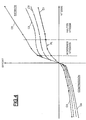
- curve CO illustrates a damping law obtained by a floating valve of the type illustrated in FIG. 2 while curve C1 illustrates the damping law obtained by a conical floating valve such as that illustrated in FIG. 3.
- the curve C1 is located below the curve CO which translates, at equal speed, by a less effort on the shock absorber.
- the curve C1 presents a zone PL substantially flat in which an increase in speed occurs results in a very minimal increase in the effort exerted on the shock absorber. This PL platform, leading to the obtaining of a point inflection, does not reduce the effort too much at medium speed while ensuring a reduction in effort at high speed.
- the preload of the conical washer makes it possible to adjust the law damping, especially at low speeds, while retaining the plateau area, as illustrated by curves C2 and C3.
Description
- la figure 1 est une coupe longitudinale d'un tube d'amortisseur équipé d'un piston à clapet flottant selon l'art antérieur,
- la figure 2 est une vue plus détaillée du piston à clapet flotttant de la figure 1,
- la figure 3 est une vue en coupe d'un piston à clapet flottant selon l'invention, et
- la figure 4 illustre différentes lois d'amortissement.
Claims (5)
- Piston à clapet pour tube d'amortisseur hydraulique, comprenant un corps de piston (116) possédant un passage de fluide (112) coopérant avec un clapet flottant (115) pour contrôler dans les deux sens le débit de fluide à travers le passage, caractérisé par le fait que le clapet flottant comporte une rondelle conique (115) dont la flèche (f) à l'état libre est comprise entre 0,1 fois et 2 fois l'épaisseur (e) de ladite rondelle.
- Piston selon la revendication 1, caractérisé par le fait que la rondelle conique (115) est précontrainte.
- Piston selon la revendication 1 ou 2, caractérisé par le fait que le corps (116) du piston supporte un empilement de plaques comportant une plaque annulaire centrale (130) supportant une plaque annulaire supérieure (114) débordant légèrement de la plaque centrale (130), par le fait que la rondelle conique (115) vient d'une part en appui sur le corps (116) du piston et d'autre part contre le bord libre de la plaque annulaire supérieure (114), et par le fait qu'en phase de compression de l'amortisseur, la rondelle (115) est apte à fléchir pour se décoller du corps du piston tandis qu'en phase de détente, la rondelle conique est apte à se décoller de la plaque supérieure (114).
- Piston selon la revendication 3, caractérisé par le fait qu'il comprend au moins une plaque annulaire de calage (140), ayant une épaisseur choisie, disposée entre la plaque annulaire centrale (130) et le corps de piston (116).
- Rondelle conique pour clapet flottant d'amortisseur hydraulique tel que défini dans l'une des revendication 1 à 4, caractérisée par le fait que la flèche (f) de la rondelle conique (115) à l'état libre est comprise ente 0,1 fois et 2 fois l'épaisseur(e) de ladite rondelle (115).
Applications Claiming Priority (4)
| Application Number | Priority Date | Filing Date | Title |
|---|---|---|---|
| FR9510267A FR2738317B1 (fr) | 1995-08-31 | 1995-08-31 | Piston a clapet flottant pour tube d'amortisseur hydraulique, notamment de type monotube |
| FR9510267 | 1995-08-31 | ||
| US08/735,258 US6247563B1 (en) | 1995-08-31 | 1996-10-22 | Piston with floating valve for hydraulic damper tube, especially one of the monotube type |
| JP8286688A JPH10132012A (ja) | 1995-08-31 | 1996-10-29 | 油圧ダンパ用フロート弁付きピストン |
Publications (2)
| Publication Number | Publication Date |
|---|---|
| EP0762013A1 EP0762013A1 (fr) | 1997-03-12 |
| EP0762013B1 true EP0762013B1 (fr) | 2001-12-05 |
Family
ID=27253093
Family Applications (1)
| Application Number | Title | Priority Date | Filing Date |
|---|---|---|---|
| EP96401729A Expired - Lifetime EP0762013B1 (fr) | 1995-08-31 | 1996-08-05 | Piston à clapet flottant pour tube d'amortisseur hydraulique, notamment de type monotube |
Country Status (6)
| Country | Link |
|---|---|
| US (1) | US6247563B1 (fr) |
| EP (1) | EP0762013B1 (fr) |
| JP (1) | JPH10132012A (fr) |
| DE (1) | DE69617567T2 (fr) |
| ES (1) | ES2169216T3 (fr) |
| FR (1) | FR2738317B1 (fr) |
Families Citing this family (21)
| Publication number | Priority date | Publication date | Assignee | Title |
|---|---|---|---|---|
| US5709290A (en) * | 1996-02-20 | 1998-01-20 | General Motors Corporation | Monotube damper valve |
| DE19842840A1 (de) | 1998-09-18 | 2000-03-23 | Zahnradfabrik Friedrichshafen | Dämpfungsventil |
| GB2356913B (en) | 1999-11-30 | 2003-02-19 | Delphi Tech Inc | Shock absorber |
| DE10140580A1 (de) * | 2000-12-16 | 2002-06-20 | Stabilus Gmbh | Kolben-Zylinderaggregat mit einer geschwindigkeitsabhängigen Dämpfkraft |
| US6655512B2 (en) * | 2000-12-19 | 2003-12-02 | Delphi Technologies, Inc. | Variable area low speed orifice in a vehicle damper |
| KR100455213B1 (ko) * | 2001-05-02 | 2004-11-08 | 주식회사 만도 | 쇽 업소버 |
| US6981578B2 (en) | 2003-07-31 | 2006-01-03 | Troy Leiphart | Non-pressurized monotube shock absorber |
| US7104180B2 (en) * | 2003-11-04 | 2006-09-12 | Delphi Technologies, Inc. | Low noise linear actuator |
| FR2883613B1 (fr) * | 2005-03-22 | 2010-09-10 | Peugeot Citroen Automobiles Sa | Dispositif d'amortissement a obturateur entre appui et cloche d'inversion |
| JP2008185177A (ja) * | 2007-01-31 | 2008-08-14 | Kayaba Ind Co Ltd | バルブ構造 |
| US7628257B1 (en) * | 2007-06-15 | 2009-12-08 | Kv Ip Holdings Ltd | Hydraulic damper for drawer |
| US8025135B1 (en) | 2007-06-15 | 2011-09-27 | KV IP Holdings Ltd. | Hydraulic damping device for drawer |
| US8127901B1 (en) | 2007-06-15 | 2012-03-06 | KV IP Holdings Ltd. | Hydraulic damping device for drawer |
| JP5290701B2 (ja) * | 2008-03-26 | 2013-09-18 | 日立オートモティブシステムズ株式会社 | 流体圧緩衝器 |
| JP5418778B2 (ja) * | 2010-02-26 | 2014-02-19 | 日立オートモティブシステムズ株式会社 | 緩衝器 |
| DE112014004495T5 (de) * | 2013-09-30 | 2016-07-21 | Showa Corporation | Druckdämpfer und Dämpfungskrafterzeugungsmechanismus |
| PL3068264T3 (pl) * | 2013-12-13 | 2019-01-31 | Kesseböhmer Produktions GmbH & Co. KG | Hamulec bezpieczeństwa dla teleskopowej kolumny meblowej |
| JP5719066B1 (ja) * | 2014-08-26 | 2015-05-13 | 株式会社ショーワ | 圧力緩衝装置 |
| US9682605B2 (en) * | 2015-02-25 | 2017-06-20 | Michael A Ankney | Variable dampening speed piston head assembly for radio controlled cars shock absorber and method |
| CN209908391U (zh) * | 2019-04-04 | 2020-01-07 | 东莞凯丰家居用品有限公司 | 一种伸缩梯杆单元 |
| US11872859B1 (en) * | 2022-08-03 | 2024-01-16 | GM Global Technology Operations LLC | Top mount hydraulic bump stop |
Family Cites Families (62)
| Publication number | Priority date | Publication date | Assignee | Title |
|---|---|---|---|---|
| CH58973A (de) * | 1912-01-27 | 1913-04-16 | Stahl Ind Mit Beschraenkter Ha | Federnde Unterlagsplatte |
| GB311754A (en) * | 1928-05-16 | 1929-07-11 | Rheinische Metallw & Maschf | Improvements in hydraulic shock absorbers |
| DE958532C (de) * | 1953-11-27 | 1957-02-21 | Volkswagenwerk G M B H | Ventil fuer hydraulische Stossdaempfer von Kraftfahrzeugen |
| BE627430A (fr) * | 1958-03-15 | |||
| US3107905A (en) * | 1960-10-19 | 1963-10-22 | Charles D Lucas | Belleville spring elastic suspension |
| FR1542408A (fr) * | 1964-01-09 | 1968-10-18 | Piston d'amortisseur à clapet flottant | |
| US3430648A (en) * | 1966-08-19 | 1969-03-04 | Fruehauf Corp | Vent check valve |
| CH472601A (de) * | 1967-11-16 | 1969-05-15 | Rheinmetall Gmbh | Kolben für Schwingungsdämpfer |
| US3553429A (en) * | 1968-11-18 | 1971-01-05 | Eastman Kodak Co | Temperature control circuit |
| US3592164A (en) * | 1969-04-01 | 1971-07-13 | Gen Motors Corp | Shock absorber piston rod seal assembly with belleville washer |
| US3682466A (en) * | 1970-05-04 | 1972-08-08 | Edgewater Corp | Composite belleville type springs and manufacture |
| GB1365306A (en) * | 1970-09-08 | 1974-08-29 | Girling Ltd | Fluid flow control valves |
| US3845782A (en) * | 1970-12-14 | 1974-11-05 | Girling Ltd | Flow control valve for hydraulic damper and the like |
| US3844389A (en) * | 1972-07-17 | 1974-10-29 | C Bourcier | Pistons for hydraulic shock absorbers |
| US3831626A (en) * | 1972-12-14 | 1974-08-27 | Peddinghaus Carl Ullrich Dr | Piston for a shock absorber |
| JPS5825896B2 (ja) * | 1974-06-28 | 1983-05-30 | トキコ株式会社 | カンシヨウキノ ゲンスイリヨクハツセイソウチ |
| US3951393A (en) * | 1974-07-22 | 1976-04-20 | Borg-Warner Corporation | Fulcrums for Belleville springs |
| DE2526775A1 (de) * | 1974-07-24 | 1976-02-12 | Bbc Brown Boveri & Cie | Armierte tellerfeder |
| GB1482813A (en) * | 1974-10-23 | 1977-08-17 | Woodhead Ltd J | Shock absorbers |
| US3957140A (en) * | 1975-02-11 | 1976-05-18 | Carl Ullrich Peddinghaus | Shock-absorber piston |
| JPS5824661B2 (ja) * | 1975-06-18 | 1983-05-23 | トキコ株式会社 | 緩衝器における減衰力発生装置 |
| GB1549776A (en) * | 1975-08-07 | 1979-08-08 | Girling Ltd | Double acting valved pistons |
| FR2327465A1 (fr) * | 1975-10-09 | 1977-05-06 | Commissariat Energie Atomique | Clapet a etranglement variable, notamment pour un amortisseur de suspension |
| US4031936A (en) * | 1975-11-14 | 1977-06-28 | Illinois Tool Works Inc. | Preassembled spring washer fastener unit |
| US4045009A (en) * | 1975-11-17 | 1977-08-30 | General Motors Corporation | Energy absorbing unit with improved control valve |
| DE2600820C3 (de) * | 1976-01-12 | 1982-02-04 | Volkswagenwerk Ag, 3180 Wolfsburg | Tellerfederventil für Stoßdämpfer |
| SU555243A1 (ru) * | 1976-01-14 | 1977-04-25 | Предприятие П/Я А-3573 | Тарельчата пружина |
| DE7802850U1 (de) * | 1978-02-01 | 1979-07-12 | Christian Bauer Kg Ringfabrik, 7063 Welzheim | Tellerfedersatz |
| JPS55149438A (en) * | 1979-05-04 | 1980-11-20 | Yamaha Motor Co Ltd | Hydraulic buffer |
| DE3100886A1 (de) * | 1981-01-14 | 1982-08-05 | Fichtel & Sachs Ag, 8720 Schweinfurt | Hydraulischer schwingungsdaempfer mit geraeuscharmen daempfventilen |
| JPS5894929U (ja) * | 1981-12-18 | 1983-06-28 | トキコ株式会社 | 油圧緩衝器 |
| US4610332A (en) * | 1981-11-05 | 1986-09-09 | Ford Motor Company | Velocity sensitive valve element for a shock absorber |
| JPS5891945A (ja) * | 1981-11-24 | 1983-06-01 | Nissan Motor Co Ltd | シヨツクアブソ−バの振動減衰バルブ |
| GB8316722D0 (en) * | 1983-06-20 | 1983-07-20 | Laser Eng Dev Ltd | Apparatus for hydraulic damping |
| US4624347A (en) * | 1984-01-23 | 1986-11-25 | Ford Motor Company | Piston assembly for shock absorber |
| US4615420A (en) * | 1984-01-23 | 1986-10-07 | Ford Motor Company | Piston assembly for shock absorber |
| SU1201580A1 (ru) * | 1984-04-11 | 1985-12-30 | Воронежский технологический институт | Тарельчата пружина |
| US4724937A (en) * | 1984-09-04 | 1988-02-16 | General Motors Corporation | Hydraulic damper for vehicles with variable deflected disk piston valving |
| JPS6314038U (fr) * | 1986-07-14 | 1988-01-29 | ||
| FR2611844B1 (fr) * | 1987-03-06 | 1989-07-13 | Bourcier Carbon Christian | Assemblage de piston pour amortisseur hydraulique |
| US4790704A (en) * | 1987-09-22 | 1988-12-13 | Allied-Signal Inc. | Retainer assembly |
| JPH01102536U (fr) * | 1987-12-28 | 1989-07-11 | ||
| CA1310989C (fr) * | 1988-04-06 | 1992-12-01 | Mitsuo Sasaki | Amortisseur a caracteristiques d'absorption variables en fonction de la vitesse de deplacement du piston |
| JPH0231040A (ja) * | 1988-07-20 | 1990-02-01 | Tokico Ltd | 油圧緩衝器 |
| US5042624A (en) * | 1988-09-29 | 1991-08-27 | Atsugi Unisia Corporation | Hydraulic shock absorber with pre-loaded valve for linear variation characteristics of damping force |
| GB2226620B (en) * | 1988-10-25 | 1992-11-04 | Tokico Ltd | Hydraulic damper |
| JPH0292154U (fr) * | 1989-01-10 | 1990-07-23 | ||
| US4972929A (en) * | 1989-06-07 | 1990-11-27 | Lord Corporation | Bidirectional dual disc valve assembly |
| US5332069A (en) * | 1989-08-31 | 1994-07-26 | Kayaba Kogyo Kabushiki Kaisha | Shock absorber |
| JPH03157533A (ja) * | 1989-11-16 | 1991-07-05 | Tokico Ltd | 油圧緩衝器 |
| SU1733757A1 (ru) * | 1990-03-26 | 1992-05-15 | Херсонский Индустриальный Институт | Тарельчата пружина |
| DE4025146A1 (de) * | 1990-08-08 | 1992-02-27 | Teckentrup Gmbh & Co Kg | Federnde scheibe zum sichern von schrauben, muttern oder dergleichen |
| US5154263A (en) * | 1990-12-11 | 1992-10-13 | Monroe Auto Equipment Company | Method and apparatus for controlling the flow of damping fluid through a piston |
| US5325942A (en) * | 1991-03-14 | 1994-07-05 | Monroe Auto Equipment Company | Tunable hydraulic valve for shock absorber |
| DE4139746A1 (de) * | 1991-12-03 | 1993-06-09 | August Bilstein Gmbh & Co. Kg, 5828 Ennepetal, De | Kolben fuer einen hydraulischen schwingungsdaempfer |
| FR2693524B1 (fr) * | 1992-07-10 | 1994-12-23 | Carbon Ste Fse Amortisseurs | Piston à clapet flottant perfectionné pour amortisseur hydraulique, notamment le type monotube pressurisé. |
| US5496142A (en) * | 1993-07-20 | 1996-03-05 | Applied Materials, Inc. | Slotted conical spring washer |
| JP3471438B2 (ja) * | 1993-12-06 | 2003-12-02 | 株式会社ショーワ | 緩衝器のバルブ構造 |
| NL1001056C2 (nl) * | 1995-08-25 | 1997-02-27 | Maasland Nv | Landbouwmachine voor het verplaatsen van op de grond liggend gewas. |
| US5823306A (en) * | 1996-11-12 | 1998-10-20 | Tenneco Automotive Inc. | Stroke dependent damping |
| US5755305A (en) * | 1997-02-07 | 1998-05-26 | Monroe Auto Equipment Division Of Tenneco Automotive Inc. | Hydraulic vibration damper with noise reducing valve structure |
| GB2337097A (en) * | 1998-05-07 | 1999-11-10 | Delphi France Automotive Sys | Hydraulic shock absorber |
-
1995
- 1995-08-31 FR FR9510267A patent/FR2738317B1/fr not_active Expired - Fee Related
-
1996
- 1996-08-05 DE DE69617567T patent/DE69617567T2/de not_active Expired - Fee Related
- 1996-08-05 EP EP96401729A patent/EP0762013B1/fr not_active Expired - Lifetime
- 1996-08-05 ES ES96401729T patent/ES2169216T3/es not_active Expired - Lifetime
- 1996-10-22 US US08/735,258 patent/US6247563B1/en not_active Expired - Fee Related
- 1996-10-29 JP JP8286688A patent/JPH10132012A/ja active Pending
Also Published As
| Publication number | Publication date |
|---|---|
| DE69617567T2 (de) | 2002-09-05 |
| US6247563B1 (en) | 2001-06-19 |
| FR2738317B1 (fr) | 1997-10-17 |
| EP0762013A1 (fr) | 1997-03-12 |
| ES2169216T3 (es) | 2002-07-01 |
| DE69617567D1 (de) | 2002-01-17 |
| JPH10132012A (ja) | 1998-05-22 |
| FR2738317A1 (fr) | 1997-03-07 |
Similar Documents
| Publication | Publication Date | Title |
|---|---|---|
| EP0762013B1 (fr) | Piston à clapet flottant pour tube d'amortisseur hydraulique, notamment de type monotube | |
| EP0234966B1 (fr) | Articulation hydro-élastique | |
| EP0003458B1 (fr) | Amortisseur pour un véhicule à suspension élastique | |
| FR2512906A1 (fr) | Amortisseur hydraulique telescopique a deux tubes | |
| FR2709796A1 (fr) | Dispositif d'obturation monobloc à guide centreur lubrifié pour tube d'amortisseur hydraulique pressurisé. | |
| FR2736115A1 (fr) | Amortisseur dont le piston comporte des sections d'ouverture initiale | |
| EP0359655B1 (fr) | Perfectionnements apportés aux manchons antivibratoires hydrauliques | |
| FR2933454A1 (fr) | Module d'injection pour soupape d'injection | |
| FR2723159A1 (fr) | Amortisseur hydraulique reglable | |
| FR2711201A1 (fr) | Amortisseur à effet d'amortissement variable en fonction de la charge. | |
| FR2761436A1 (fr) | Douille de guidage | |
| FR2716247A1 (fr) | Soupape d'amortissement pour un amortisseur. | |
| FR2693524A1 (fr) | Piston à clapet flottant perfectionné pour amortisseur hydraulique, notamment le type monotube pressurisé. | |
| FR2834028A1 (fr) | Soupape d'amortisseur | |
| EP0910755A1 (fr) | Piston a clapet, en particulier flottant, avec loi effort/vitesse dissymetrique pour tube d'amortisseur hydraulique | |
| EP0764795A1 (fr) | Piston à clapet pour tube d'amortisseur hydraulique | |
| EP1171724B1 (fr) | Dispositif formant amortisseur dissymetrique pour une suspension de vehicule automobile | |
| FR2783878A1 (fr) | Dispositif pour retarder l'excursion de l'aiguille d'injection d'un injecteur de carburant | |
| EP4051584A1 (fr) | Pointeau de dosage pour amortisseur de type oleopneumatique | |
| EP4051923A1 (fr) | Porte-diaphragme pour amortisseur de type oleopneumatique | |
| FR2882124A1 (fr) | Procede pour regler l'effet d'etranglement d'une soupape, notamment dans un amortisseur | |
| EP1172580A1 (fr) | Dispositif d'amortissement à structure simplifiée | |
| FR2848277A1 (fr) | Segment de piston | |
| FR3039606A1 (fr) | Dispositif d’amortissement a butee de detente hydraulique a piece d’extremite a canaux de passage de fluide | |
| FR2686957A1 (fr) | Cale hydroelastique. |
Legal Events
| Date | Code | Title | Description |
|---|---|---|---|
| PUAI | Public reference made under article 153(3) epc to a published international application that has entered the european phase |
Free format text: ORIGINAL CODE: 0009012 |
|
| AK | Designated contracting states |
Kind code of ref document: A1 Designated state(s): DE ES GB IE IT |
|
| 17P | Request for examination filed |
Effective date: 19970912 |
|
| GRAG | Despatch of communication of intention to grant |
Free format text: ORIGINAL CODE: EPIDOS AGRA |
|
| 17Q | First examination report despatched |
Effective date: 19991116 |
|
| GRAG | Despatch of communication of intention to grant |
Free format text: ORIGINAL CODE: EPIDOS AGRA |
|
| GRAG | Despatch of communication of intention to grant |
Free format text: ORIGINAL CODE: EPIDOS AGRA |
|
| GRAG | Despatch of communication of intention to grant |
Free format text: ORIGINAL CODE: EPIDOS AGRA |
|
| GRAH | Despatch of communication of intention to grant a patent |
Free format text: ORIGINAL CODE: EPIDOS IGRA |
|
| GRAH | Despatch of communication of intention to grant a patent |
Free format text: ORIGINAL CODE: EPIDOS IGRA |
|
| GRAA | (expected) grant |
Free format text: ORIGINAL CODE: 0009210 |
|
| AK | Designated contracting states |
Kind code of ref document: B1 Designated state(s): DE ES GB IE IT |
|
| PG25 | Lapsed in a contracting state [announced via postgrant information from national office to epo] |
Ref country code: IE Free format text: LAPSE BECAUSE OF FAILURE TO SUBMIT A TRANSLATION OF THE DESCRIPTION OR TO PAY THE FEE WITHIN THE PRESCRIBED TIME-LIMIT Effective date: 20011205 |
|
| REG | Reference to a national code |
Ref country code: GB Ref legal event code: IF02 |
|
| REG | Reference to a national code |
Ref country code: IE Ref legal event code: FG4D Free format text: FRENCH |
|
| REF | Corresponds to: |
Ref document number: 69617567 Country of ref document: DE Date of ref document: 20020117 |
|
| GBT | Gb: translation of ep patent filed (gb section 77(6)(a)/1977) |
Effective date: 20020129 |
|
| REG | Reference to a national code |
Ref country code: ES Ref legal event code: FG2A Ref document number: 2169216 Country of ref document: ES Kind code of ref document: T3 |
|
| REG | Reference to a national code |
Ref country code: IE Ref legal event code: FD4D |
|
| PGFP | Annual fee paid to national office [announced via postgrant information from national office to epo] |
Ref country code: GB Payment date: 20020729 Year of fee payment: 7 |
|
| PGFP | Annual fee paid to national office [announced via postgrant information from national office to epo] |
Ref country code: ES Payment date: 20020730 Year of fee payment: 7 |
|
| PLBE | No opposition filed within time limit |
Free format text: ORIGINAL CODE: 0009261 |
|
| STAA | Information on the status of an ep patent application or granted ep patent |
Free format text: STATUS: NO OPPOSITION FILED WITHIN TIME LIMIT |
|
| 26N | No opposition filed | ||
| PG25 | Lapsed in a contracting state [announced via postgrant information from national office to epo] |
Ref country code: GB Free format text: LAPSE BECAUSE OF NON-PAYMENT OF DUE FEES Effective date: 20030805 |
|
| PG25 | Lapsed in a contracting state [announced via postgrant information from national office to epo] |
Ref country code: ES Free format text: LAPSE BECAUSE OF NON-PAYMENT OF DUE FEES Effective date: 20030806 |
|
| GBPC | Gb: european patent ceased through non-payment of renewal fee |
Effective date: 20030805 |
|
| PGFP | Annual fee paid to national office [announced via postgrant information from national office to epo] |
Ref country code: DE Payment date: 20041028 Year of fee payment: 9 |
|
| REG | Reference to a national code |
Ref country code: ES Ref legal event code: FD2A Effective date: 20030806 |
|
| PG25 | Lapsed in a contracting state [announced via postgrant information from national office to epo] |
Ref country code: IT Free format text: LAPSE BECAUSE OF NON-PAYMENT OF DUE FEES Effective date: 20050805 |
|
| PG25 | Lapsed in a contracting state [announced via postgrant information from national office to epo] |
Ref country code: DE Free format text: LAPSE BECAUSE OF NON-PAYMENT OF DUE FEES Effective date: 20060301 |