EP0761518B1 - Einstellvorrichtung mit selbsttätigem Längenausgleich für einen Betätigungszug - Google Patents
Einstellvorrichtung mit selbsttätigem Längenausgleich für einen Betätigungszug Download PDFInfo
- Publication number
- EP0761518B1 EP0761518B1 EP96110960A EP96110960A EP0761518B1 EP 0761518 B1 EP0761518 B1 EP 0761518B1 EP 96110960 A EP96110960 A EP 96110960A EP 96110960 A EP96110960 A EP 96110960A EP 0761518 B1 EP0761518 B1 EP 0761518B1
- Authority
- EP
- European Patent Office
- Prior art keywords
- adjusting device
- receptacle
- segments
- detent
- actuating
- Prior art date
- Legal status (The legal status is an assumption and is not a legal conclusion. Google has not performed a legal analysis and makes no representation as to the accuracy of the status listed.)
- Expired - Lifetime
Links
- 230000000903 blocking effect Effects 0.000 claims description 14
- 210000002445 nipple Anatomy 0.000 claims description 7
- 230000000717 retained effect Effects 0.000 claims 1
- 239000000725 suspension Substances 0.000 claims 1
- 239000011324 bead Substances 0.000 description 3
- 238000004519 manufacturing process Methods 0.000 description 3
- 230000000694 effects Effects 0.000 description 2
- 230000002441 reversible effect Effects 0.000 description 2
- 230000005540 biological transmission Effects 0.000 description 1
- 230000008014 freezing Effects 0.000 description 1
- 238000007710 freezing Methods 0.000 description 1
- 238000007726 management method Methods 0.000 description 1
- 238000000034 method Methods 0.000 description 1
- 230000036316 preload Effects 0.000 description 1
- 238000010257 thawing Methods 0.000 description 1
Images


Classifications
-
- B—PERFORMING OPERATIONS; TRANSPORTING
- B60—VEHICLES IN GENERAL
- B60T—VEHICLE BRAKE CONTROL SYSTEMS OR PARTS THEREOF; BRAKE CONTROL SYSTEMS OR PARTS THEREOF, IN GENERAL; ARRANGEMENT OF BRAKING ELEMENTS ON VEHICLES IN GENERAL; PORTABLE DEVICES FOR PREVENTING UNWANTED MOVEMENT OF VEHICLES; VEHICLE MODIFICATIONS TO FACILITATE COOLING OF BRAKES
- B60T11/00—Transmitting braking action from initiating means to ultimate brake actuator without power assistance or drive or where such assistance or drive is irrelevant
- B60T11/04—Transmitting braking action from initiating means to ultimate brake actuator without power assistance or drive or where such assistance or drive is irrelevant transmitting mechanically
- B60T11/06—Equalising arrangements
-
- F—MECHANICAL ENGINEERING; LIGHTING; HEATING; WEAPONS; BLASTING
- F16—ENGINEERING ELEMENTS AND UNITS; GENERAL MEASURES FOR PRODUCING AND MAINTAINING EFFECTIVE FUNCTIONING OF MACHINES OR INSTALLATIONS; THERMAL INSULATION IN GENERAL
- F16C—SHAFTS; FLEXIBLE SHAFTS; ELEMENTS OR CRANKSHAFT MECHANISMS; ROTARY BODIES OTHER THAN GEARING ELEMENTS; BEARINGS
- F16C1/00—Flexible shafts; Mechanical means for transmitting movement in a flexible sheathing
- F16C1/10—Means for transmitting linear movement in a flexible sheathing, e.g. "Bowden-mechanisms"
- F16C1/22—Adjusting; Compensating length
-
- F—MECHANICAL ENGINEERING; LIGHTING; HEATING; WEAPONS; BLASTING
- F16—ENGINEERING ELEMENTS AND UNITS; GENERAL MEASURES FOR PRODUCING AND MAINTAINING EFFECTIVE FUNCTIONING OF MACHINES OR INSTALLATIONS; THERMAL INSULATION IN GENERAL
- F16C—SHAFTS; FLEXIBLE SHAFTS; ELEMENTS OR CRANKSHAFT MECHANISMS; ROTARY BODIES OTHER THAN GEARING ELEMENTS; BEARINGS
- F16C2326/00—Articles relating to transporting
- F16C2326/01—Parts of vehicles in general
Definitions
- the invention relates to an adjusting device automatic length compensation for an actuating cable, especially for a cable pull for actuating brake shoes a vehicle by means of an actuating element, such as a Hand brake lever, a foot parking brake or the like.
- the invention is based on the object Adjustment device with automatic length compensation of the type mentioned, in particular for a handbrake from Specify vehicles, which in a simple manufacture and assembly an automatic length compensation Actuating cables enables.
- Adjustment device with the features mentioned above solved in that the adjusting device Housing-like receptacle with two pivoted, through Spring elements preloaded locking elements has, each with an actuating cable, in particular Cable can be connected, and with one in the recording slidably guided locking piece, which when actuated an actuating cable or a cable pull of one Locking segments unlock the position in one of the locking segments blocking position is transferable.
- This will in advantageously ensures that at a Non-actuation of the actuating cable by the locking segments Blocking piece are not locked, so that due to the bias the locking segments an automatic length compensation of the Actuating cables or cables can be made.
- An advantageous embodiment of the invention in particular through a structurally simple structure distinguished, is that the locking segments by means of especially bolts secured in the Recording are held.
- the spring element has two legs, the one Leg on the mount and the other leg on the supports the respective locking segment.
- An advantageous development of the invention consists in that the locking piece two engaging behind the locking segments, has lateral bends with one counter tooth each, each assigned to an external toothing of the locking segments are. Because of this measure is a safe and permanent one Locking the locking segments when the Actuating cable guaranteed.
- connection between the actuator and the Adjustment device is advantageously produced in that an end fitting of a connector between the Actuator and the adjusting device with one bolt-shaped end hooked into a hole in the locking piece is.
- the assembly of the adjustment device for example in a vehicle is simplified in that the Locking segments each have a hook-like attachment for receiving is provided by nipples arranged at the ends of the cables.
- the cables are advantageously guided in hose sockets, the hose sockets on vehicle-side receptacles are supported.
- the adjusting device has a detachable Lock pin on, in particular in an elongated hole of the recording can be used and the locking piece in one of the locking segments locking position fixed.
- This locking pin is in the Delivery condition of the adjusting device in the slot used, the locking segments against the spring force in a extreme swiveled-in position and are in this Position held by the locking piece. Let her through the nipples of the cables pull comfortably into the mountings on the Attach the locking segments, then the locking pin is removed from the adjusting device, so that the Locking piece in a position unlocking the locking segments reached.
- the handbrake system for a motor vehicle has one arranged in the vehicle interior pivotable handbrake lever 1, which over a Connection piece 2, for example a linkage or a cable, with the adjusting device 3 is connected.
- the Adjustment device 3 can either be inside the vehicle or be arranged on the outside of the vehicle, just as it is conceivable that instead of a lever to be operated by hand with the Parking brake is provided.
- the Setting device 3 has a housing-like Recording 4 on which two designed as locking elements Locking segments 5, locking lever or the like Bolts 6 are stored.
- the locking segments 5 are by means of Spring elements 11 biased in one direction of rotation, in which the two locking segments 5 each outward in the direction of Hand brake lever 1 or are pivoted in the direction of travel.
- One leg end of the spring element 11 is supported for this on the receptacle 4, while the other leg end on the assigned locking segment 5 is mounted.
- With the rest segment 5 interacts with a locking piece 14, the locking segments 5 a toothing 12 and the locking piece 14 an associated Have counter teeth 13.
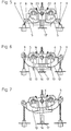
- the handbrake lever 1 end facing the connector 2 or the wire rope articulated by the end fitting 15 of the connecting piece 2 or of the rope leading away from the hand brake lever 1 in a T-shape is formed and, as can be seen in particular from FIG. 4, with the bolt-shaped end 23 in a bore of the locking piece 14 is mounted.
- the recording 4 is on opposite Pages each formed an elongated hole 16, in which the engage bolt-shaped ends 23 of the end fitting 15 and for the displaceability in the longitudinal direction of the locking piece 14 to care.
- the locking piece 14 is in the longitudinal direction on the Recording 4 slidable and at the same time opposite Connector 2 or the rope pivotable. Do it Beads 18 in the housing-shaped receptacle 4 a guide of Blocking piece 14.
- a Vehicle-side stop 17 is provided, which serves to that when the handbrake is not activated, a stop for the Recording 4 of the adjusting device 3 is provided. If the Recording 4 reaches the stop 17, the locking piece occurs 14 with its counter-toothing 13 out of engagement with the toothing 12 the rest segments 5.
- a hook-shaped Mount 7 for receiving the cables of the brake cables 9th connected nipples 8 provided.
- the brake cables 9 are with their hose sockets 19 on vehicle-side receptacles 20 supported.
- Figure 7 also takes into account the case that the brakes 10th different due to production or wear Have braking distances. 7 shows the right brake has more clearance than the left brake, so that to compensate for this additional brake play Recording 4 or the setting device in a counterclockwise direction something is pivoted and it is tilted Adjustment device 3 comes until the brake play compensation is carried out. If the handbrake is applied further, it happens then to a uniform transmission of the braking force over the Cable 9 on the brakes 10.
- the device according to the invention acts not only in the sense of Initial setting, but as described above, also as permanent adjustment during the operation of the vehicle.
- the setting i.e. the rotational movement of the Locking segments 5 reversible, which is a particular advantage in With regard to freezing of the brake shoes of the brakes 10 affects.
- the handbrake is pulled Brake shoes are frozen, and subsequently the Hand brake lever 1 is lowered into the open position, it comes initially to readjust the cables 9 by the fictitious lots occurring in the process are removed from the system becomes. If the brake 10 now defrosts, the effect Return springs in the brakes 10 that the locking segments 5th be reset again because the brake is in Open position and accordingly the locking piece 14 is not is in engagement with the locking segments 5.
- This reversible adjustment of the invention Device is a major advantage over the known adjustment devices, which only in one direction, namely in the direction of a re-enactment, and against one Reversal of the adjustment effect are blocked.
Landscapes
- Engineering & Computer Science (AREA)
- Mechanical Engineering (AREA)
- General Engineering & Computer Science (AREA)
- Transportation (AREA)
- Health & Medical Sciences (AREA)
- Oral & Maxillofacial Surgery (AREA)
- Flexible Shafts (AREA)
- Braking Arrangements (AREA)
Applications Claiming Priority (4)
| Application Number | Priority Date | Filing Date | Title |
|---|---|---|---|
| DE19529459 | 1995-08-10 | ||
| DE19529459 | 1995-08-10 | ||
| DE19546931A DE19546931C2 (de) | 1995-08-10 | 1995-12-15 | Einstellvorrichtung mit selbsttätigem Längenausgleich für einen Betätigungszug |
| DE19546931 | 1995-12-15 |
Publications (2)
| Publication Number | Publication Date |
|---|---|
| EP0761518A1 EP0761518A1 (de) | 1997-03-12 |
| EP0761518B1 true EP0761518B1 (de) | 1999-10-27 |
Family
ID=26017594
Family Applications (1)
| Application Number | Title | Priority Date | Filing Date |
|---|---|---|---|
| EP96110960A Expired - Lifetime EP0761518B1 (de) | 1995-08-10 | 1996-07-06 | Einstellvorrichtung mit selbsttätigem Längenausgleich für einen Betätigungszug |
Country Status (2)
| Country | Link |
|---|---|
| EP (1) | EP0761518B1 (es) |
| ES (1) | ES2139283T3 (es) |
Families Citing this family (1)
| Publication number | Priority date | Publication date | Assignee | Title |
|---|---|---|---|---|
| CN118327394B (zh) * | 2024-04-18 | 2025-09-09 | 重庆长安汽车股份有限公司 | 一种前罩锁的调节结构及前罩锁、车辆 |
Family Cites Families (3)
| Publication number | Priority date | Publication date | Assignee | Title |
|---|---|---|---|---|
| DE8435833U1 (de) * | 1984-12-07 | 1985-04-18 | Maschinenbau Knott Eggstätt Ing. Valentin Knott, 8201 Eggstätt | Bremsseilzugbefestigung |
| DE3820978C2 (de) * | 1988-06-22 | 1999-01-21 | Teves Gmbh Alfred | Automatische Nachstellvorrichtung für Trommelbremsen |
| FR2710302B1 (fr) * | 1993-09-21 | 1995-12-15 | Blg Systemes | Dispositif perfectionné pour la mise sous tension et le rattrapage automatique du jeu d'un câble de commande. |
-
1996
- 1996-07-06 ES ES96110960T patent/ES2139283T3/es not_active Expired - Lifetime
- 1996-07-06 EP EP96110960A patent/EP0761518B1/de not_active Expired - Lifetime
Also Published As
| Publication number | Publication date |
|---|---|
| ES2139283T3 (es) | 2000-02-01 |
| EP0761518A1 (de) | 1997-03-12 |
Similar Documents
| Publication | Publication Date | Title |
|---|---|---|
| EP0975498B1 (de) | Feststellbremsanlage für fahrzeuge | |
| DE102018131844A1 (de) | Parksperreinrichtung in einem Fahrzeug | |
| WO1993022571A1 (de) | Vorrichtung zur längenkorrektur von mechanisch-flexiblen fernbetätigungen | |
| EP1252049B1 (de) | Seilzug-vorrichtung zur betätigung eines stellgliedes | |
| DE19546931C2 (de) | Einstellvorrichtung mit selbsttätigem Längenausgleich für einen Betätigungszug | |
| EP3165419B1 (de) | Auflaufbremsanlage für kraftfahrzeuganhänger | |
| DE102008054469A1 (de) | Parksperrenvorrichtung für ein Kraftfahrzeuggetriebe | |
| EP0904223B1 (de) | Einstellvorrichtung mit selbsttätigem längenausgleich für einen betätigungszug | |
| EP0761518B1 (de) | Einstellvorrichtung mit selbsttätigem Längenausgleich für einen Betätigungszug | |
| DE3901989A1 (de) | Fahrzeugbremssystem | |
| DE19618422A1 (de) | Vorrichtung zur selbsttätigen Längenkorrektur von Seilzügen | |
| DE19618423C2 (de) | Vorrichtung zur selbsttätigen Längenkorrektur von Seilzügen | |
| EP1241366B1 (de) | Vorrichtung zur selbsttätigen Längenkorrektur von Betätigungen | |
| DE19618421C2 (de) | Vorrichtung zur selbsttätigen Längenkorrektur von Seilzügen | |
| DE19718320C2 (de) | Einstellvorrichtung mit selbsttätigem Längenausgleich für ein Seilzugsystem o. dgl. | |
| EP3347626B1 (de) | Parksperrenvorrichtung für ein kraftfahrzeuggetriebe | |
| DE102006036283A1 (de) | Einstellmechanismus zur Längeneinstellung eines Bowdenzugs | |
| DE19729468C2 (de) | Fensterheberantrieb für einen manuellen Seilzug-Fensterheber | |
| DE19734572C2 (de) | Einstellvorrichtung mit selbsttätigem Längenausgleich für einen Betätigungszug | |
| DE19734573C2 (de) | Einstellvorrichtung mit selbsttätigem Längenausgleich für Seilzüge, insbesondere für Fahrzeugbremsen | |
| EP0811793A2 (de) | Vorrichtung zur Neutralstellung eines Getriebes | |
| EP1984215A1 (de) | Vorrichtung zum mechanischen lösen einer motorisch betätigten feststellbremse für ein kraftfahrzeug | |
| EP0861177B1 (de) | Vorrichtung zur selbsttätigen längenkorrektur von seilzügen | |
| DE19832502A1 (de) | Steuerung für einen stufenlosen Kraftwagentürfeststeller | |
| EP0768471B1 (de) | Vorrichtung zur selbsttätigen Längeneinstellung bzw. -nachstellung von mechanisch-flexiblen Betätigungszügen |
Legal Events
| Date | Code | Title | Description |
|---|---|---|---|
| PUAI | Public reference made under article 153(3) epc to a published international application that has entered the european phase |
Free format text: ORIGINAL CODE: 0009012 |
|
| 17P | Request for examination filed |
Effective date: 19961207 |
|
| AK | Designated contracting states |
Kind code of ref document: A1 Designated state(s): DE ES FR GB IT NL |
|
| GRAG | Despatch of communication of intention to grant |
Free format text: ORIGINAL CODE: EPIDOS AGRA |
|
| GRAG | Despatch of communication of intention to grant |
Free format text: ORIGINAL CODE: EPIDOS AGRA |
|
| GRAH | Despatch of communication of intention to grant a patent |
Free format text: ORIGINAL CODE: EPIDOS IGRA |
|
| 17Q | First examination report despatched |
Effective date: 19990407 |
|
| GRAH | Despatch of communication of intention to grant a patent |
Free format text: ORIGINAL CODE: EPIDOS IGRA |
|
| GRAA | (expected) grant |
Free format text: ORIGINAL CODE: 0009210 |
|
| AK | Designated contracting states |
Kind code of ref document: B1 Designated state(s): DE ES FR GB IT NL |
|
| PG25 | Lapsed in a contracting state [announced via postgrant information from national office to epo] |
Ref country code: NL Free format text: LAPSE BECAUSE OF FAILURE TO SUBMIT A TRANSLATION OF THE DESCRIPTION OR TO PAY THE FEE WITHIN THE PRESCRIBED TIME-LIMIT Effective date: 19991027 Ref country code: IT Free format text: LAPSE BECAUSE OF FAILURE TO SUBMIT A TRANSLATION OF THE DESCRIPTION OR TO PAY THE FEE WITHIN THE PRE;WARNING: LAPSES OF ITALIAN PATENTS WITH EFFECTIVE DATE BEFORE 2007 MAY HAVE OCCURRED AT ANY TIME BEFORE 2007. THE CORRECT EFFECTIVE DATE MAY BE DIFFERENT FROM THE ONE RECORDED.SCRIBED TIME-LIMIT Effective date: 19991027 |
|
| GBT | Gb: translation of ep patent filed (gb section 77(6)(a)/1977) |
Effective date: 19991027 |
|
| REF | Corresponds to: |
Ref document number: 59603468 Country of ref document: DE Date of ref document: 19991202 |
|
| ET | Fr: translation filed | ||
| REG | Reference to a national code |
Ref country code: ES Ref legal event code: FG2A Ref document number: 2139283 Country of ref document: ES Kind code of ref document: T3 |
|
| NLV1 | Nl: lapsed or annulled due to failure to fulfill the requirements of art. 29p and 29m of the patents act | ||
| PGFP | Annual fee paid to national office [announced via postgrant information from national office to epo] |
Ref country code: GB Payment date: 20000717 Year of fee payment: 5 |
|
| PGFP | Annual fee paid to national office [announced via postgrant information from national office to epo] |
Ref country code: FR Payment date: 20000718 Year of fee payment: 5 |
|
| PGFP | Annual fee paid to national office [announced via postgrant information from national office to epo] |
Ref country code: ES Payment date: 20000825 Year of fee payment: 5 |
|
| PLBE | No opposition filed within time limit |
Free format text: ORIGINAL CODE: 0009261 |
|
| STAA | Information on the status of an ep patent application or granted ep patent |
Free format text: STATUS: NO OPPOSITION FILED WITHIN TIME LIMIT |
|
| 26N | No opposition filed | ||
| PG25 | Lapsed in a contracting state [announced via postgrant information from national office to epo] |
Ref country code: GB Free format text: LAPSE BECAUSE OF NON-PAYMENT OF DUE FEES Effective date: 20010706 |
|
| PG25 | Lapsed in a contracting state [announced via postgrant information from national office to epo] |
Ref country code: ES Free format text: LAPSE BECAUSE OF NON-PAYMENT OF DUE FEES Effective date: 20010707 |
|
| GBPC | Gb: european patent ceased through non-payment of renewal fee |
Effective date: 20010706 |
|
| PG25 | Lapsed in a contracting state [announced via postgrant information from national office to epo] |
Ref country code: FR Free format text: LAPSE BECAUSE OF NON-PAYMENT OF DUE FEES Effective date: 20020329 |
|
| REG | Reference to a national code |
Ref country code: FR Ref legal event code: ST |
|
| REG | Reference to a national code |
Ref country code: ES Ref legal event code: FD2A Effective date: 20020810 |
|
| PGFP | Annual fee paid to national office [announced via postgrant information from national office to epo] |
Ref country code: DE Payment date: 20110731 Year of fee payment: 16 |
|
| REG | Reference to a national code |
Ref country code: DE Ref legal event code: R119 Ref document number: 59603468 Country of ref document: DE Effective date: 20130201 |
|
| PG25 | Lapsed in a contracting state [announced via postgrant information from national office to epo] |
Ref country code: DE Free format text: LAPSE BECAUSE OF NON-PAYMENT OF DUE FEES Effective date: 20130201 |