EP0761518A1 - Einstellvorrichtung mit selbsttätigem Längenausgleich für einen Betätigungszug - Google Patents
Einstellvorrichtung mit selbsttätigem Längenausgleich für einen Betätigungszug Download PDFInfo
- Publication number
- EP0761518A1 EP0761518A1 EP96110960A EP96110960A EP0761518A1 EP 0761518 A1 EP0761518 A1 EP 0761518A1 EP 96110960 A EP96110960 A EP 96110960A EP 96110960 A EP96110960 A EP 96110960A EP 0761518 A1 EP0761518 A1 EP 0761518A1
- Authority
- EP
- European Patent Office
- Prior art keywords
- adjusting device
- locking
- receptacle
- segments
- cable
- Prior art date
- Legal status (The legal status is an assumption and is not a legal conclusion. Google has not performed a legal analysis and makes no representation as to the accuracy of the status listed.)
- Granted
Links
- 210000002445 nipple Anatomy 0.000 claims description 7
- 239000011324 bead Substances 0.000 claims description 4
- 238000004519 manufacturing process Methods 0.000 description 3
- 230000002441 reversible effect Effects 0.000 description 2
- 230000005540 biological transmission Effects 0.000 description 1
- 230000000694 effects Effects 0.000 description 1
- 230000008014 freezing Effects 0.000 description 1
- 238000007710 freezing Methods 0.000 description 1
- 230000036316 preload Effects 0.000 description 1
- 239000000725 suspension Substances 0.000 description 1
- 238000010257 thawing Methods 0.000 description 1
Images
Classifications
-
- B—PERFORMING OPERATIONS; TRANSPORTING
- B60—VEHICLES IN GENERAL
- B60T—VEHICLE BRAKE CONTROL SYSTEMS OR PARTS THEREOF; BRAKE CONTROL SYSTEMS OR PARTS THEREOF, IN GENERAL; ARRANGEMENT OF BRAKING ELEMENTS ON VEHICLES IN GENERAL; PORTABLE DEVICES FOR PREVENTING UNWANTED MOVEMENT OF VEHICLES; VEHICLE MODIFICATIONS TO FACILITATE COOLING OF BRAKES
- B60T11/00—Transmitting braking action from initiating means to ultimate brake actuator without power assistance or drive or where such assistance or drive is irrelevant
- B60T11/04—Transmitting braking action from initiating means to ultimate brake actuator without power assistance or drive or where such assistance or drive is irrelevant transmitting mechanically
- B60T11/06—Equalising arrangements
-
- F—MECHANICAL ENGINEERING; LIGHTING; HEATING; WEAPONS; BLASTING
- F16—ENGINEERING ELEMENTS AND UNITS; GENERAL MEASURES FOR PRODUCING AND MAINTAINING EFFECTIVE FUNCTIONING OF MACHINES OR INSTALLATIONS; THERMAL INSULATION IN GENERAL
- F16C—SHAFTS; FLEXIBLE SHAFTS; ELEMENTS OR CRANKSHAFT MECHANISMS; ROTARY BODIES OTHER THAN GEARING ELEMENTS; BEARINGS
- F16C1/00—Flexible shafts; Mechanical means for transmitting movement in a flexible sheathing
- F16C1/10—Means for transmitting linear movement in a flexible sheathing, e.g. "Bowden-mechanisms"
- F16C1/22—Adjusting; Compensating length
-
- F—MECHANICAL ENGINEERING; LIGHTING; HEATING; WEAPONS; BLASTING
- F16—ENGINEERING ELEMENTS AND UNITS; GENERAL MEASURES FOR PRODUCING AND MAINTAINING EFFECTIVE FUNCTIONING OF MACHINES OR INSTALLATIONS; THERMAL INSULATION IN GENERAL
- F16C—SHAFTS; FLEXIBLE SHAFTS; ELEMENTS OR CRANKSHAFT MECHANISMS; ROTARY BODIES OTHER THAN GEARING ELEMENTS; BEARINGS
- F16C2326/00—Articles relating to transporting
- F16C2326/01—Parts of vehicles in general
Definitions
- the invention relates to an adjusting device with automatic length compensation for an actuating cable, in particular for a cable for actuating brake shoes of a vehicle by means of an actuating element, such as a hand brake lever, a foot parking brake or the like.
- the invention has for its object to provide an adjusting device with automatic length compensation of the type mentioned, in particular for a handbrake of vehicles, which allows an automatic length compensation of the actuating cables with a simple manufacture and assembly.
- the adjusting device an i. w. Housing-like receptacle with two pivotally mounted locking segments, pretensioned by spring elements, locking levers or the like, each of which can be connected to an actuating cable, in particular a cable pull, and with a locking piece which is displaceably guided in the receptacle and which, when an actuating cable or cable pull is actuated by a position unlocking the locking segments can be transferred into a position locking the locking segments.
- An advantageous embodiment of the invention which is characterized in particular by a structurally simple structure, consists in that the locking segments are held in the receptacle by means of bolts secured in particular by retaining rings.
- actuating cables suspended in the locking segments can be subjected to tension by means of the spring elements. This measure ensures that any lots from the Actuation cable is removed by a corresponding pivoting movement of the locking segments.
- the spring element has two legs, one leg being supported on the receptacle and the other leg on the respective latching segment.
- An advantageous development of the invention consists in that the locking piece has two lateral anglings engaging behind the locking segments, each with counter teeth, which are each assigned to an external toothing of the locking segments. This measure ensures that the locking segments are locked securely and permanently when the actuating cable is actuated.
- connection between the actuating element and the adjusting device is advantageously produced in that an end fitting of a connecting piece between the actuating element and the adjusting device is suspended with a bolt-shaped end in a bore of the locking piece.
- the bolt-shaped end of the end fitting of the connecting piece advantageously engages in an elongated hole in the receptacle.
- Proper guidance of the locking piece in the receptacle is ensured in that the locking piece is guided so as to be longitudinally displaceable between beads, which are provided in particular on the inner walls of the receptacle.
- the receptacle is assigned a fixed or vehicle-mounted stop, which ensures that the locking piece is not activated when the actuating element is not actuated Engagement with the detent segments occurs so that the detent segments can compensate for any slack in the actuating cable due to the spring preload.
- the assembly of the adjusting device for example in a vehicle, is simplified in that a hook-like attachment is provided in each case on outer end sections of the detent segments for receiving nipples arranged at the ends of the cable pulls.
- the cables are advantageously guided in hose sockets, the hose sockets being supported on receptacles on the vehicle.
- the adjusting device has a releasable locking pin which can be inserted in particular into an elongated hole in the receptacle and fixes the locking piece in a position locking the locking segments.
- This locking pin is inserted into the elongated hole in the delivery state of the adjusting device, the locking segments being pivoted into an extreme pivoting-in position against the spring force and being held in this position by the locking piece.
- the nipples of the cables can be conveniently hooked into the mountings on the locking segments, the locking pin then being removed from the adjusting device so that the locking piece comes into a position that unlocks the locking segments.
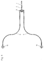
- the handbrake system for a motor vehicle shown by way of example in FIG. 1 has a pivotable handbrake lever 1 which is arranged in the vehicle interior and which is connected to the adjusting device 3 via a connecting piece 2, for example a linkage or a cable pull.
- the adjusting device 3 can be arranged either on the inside of the vehicle or on the outside of the vehicle, just as it is conceivable that instead of a lever to be operated by hand, a parking brake to be adjusted with the foot is provided.
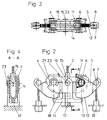
- the adjusting device 3 according to FIG. 2 has a housing-like receptacle 4, on which two locking segments 5 are pivotably mounted on bolts 6.
- the locking segments 5 are prestressed in a direction of rotation by means of spring elements 11, in which the two locking segments 5 are each pivoted outward in the direction of the hand brake lever 1 or in the direction of travel.
- one leg end of the spring element 11 is supported on the receptacle 4, while the other leg end is hooked onto the associated detent segment 5.
- a locking piece 14 interacts with the locking segment 5, the locking segments 5 having a toothing 12 and the locking piece 14 having an associated counter toothing 13.
- the connecting piece 2 or the wire rope is articulated to the locking piece 14 at its end facing the hand brake lever 1 by the end fitting 15 of the connecting piece 2 or the rope leading away from the hand brake lever 1 being T-shaped and, as in particular from FIG see, with the bolt-shaped end 23 is suspended in a bore of the locking piece 14.
- an elongated hole 16 is formed on opposite sides, in which the bolt-shaped ends 23 of the end fitting 15 engage and ensure the displaceability in the longitudinal direction of the locking piece 14.
- the locking piece 14 is displaceable in its longitudinal direction on the receptacle 4 and at the same time pivotable with respect to the connecting piece 2 or the rope. Beads 18 cause the locking piece 14 to be guided in the housing-shaped receptacle 4.
- a stop 17 on the vehicle which serves to provide a stop for the receptacle 4 of the adjusting device 3 when the handbrake is not actuated.
- the locking piece 14 with its counter-toothing 13 disengages from the toothing 12 of the locking segments 5.
- a hook-shaped suspension 7 is provided for receiving the nipples 8 connected to the cables of the brake cables 9.
- the brake cables 9 are supported with their hose sockets 19 on receptacles 20 on the vehicle.
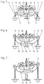
- a locking pin 22 is inserted in the slot 16 between the bolt-shaped ends 23 of the end fitting 15, which brings the locking segments 5 into engagement with the locking piece 14 in such a way that the locking segments 5 counter to the force of the Spring elements 11 are pivoted inwards.
- the nipples 8 of the cable pulls 9 can be conveniently hooked into the mountings 7 on the locking segments 5.
- the locking pin 22 is removed and the hand brake lever 1 is moved into the open position.
- the receptacle 4 comes against the stop 17, as a result of which the locking piece 14 with its counter-toothing 13 disengages from the toothing 12 of the locking segments 5.
- the locking segments 5 are pivoted outwards in the direction of the hand brake lever 1 or in the direction of travel by the force of the spring elements 11. In this way, the length compensation of the cables 9 is effected (see FIG. 6).
- Figure 7 also takes into account the case that the brakes 10 have different braking distances due to production or wear.
- the right brake has a larger play than the left brake, so that to compensate for this additional brake play, the receptacle 4 or the adjusting device is pivoted somewhat counterclockwise and the adjusting device 3 is tilted until the Brake play compensation is carried out. If the handbrake is applied further, the braking force is evenly transmitted to the brakes 10 via the cables 9.
- the device according to the invention acts not only in the sense of an initial adjustment, but also, as described above, as a permanent adjustment during the operation of the vehicle.
- the setting ie the rotational movement of the locking segments 5, is reversible, which has a particular advantage with regard to freezing of the brake shoes of the brakes 10. If the brake shoes are frozen in winter when the handbrake is pulled and the handbrake lever 1 is subsequently lowered into the open position, the cable pulls 9 are initially readjusted by removing the fictitious slack that occurs in the system. If the brake 10 now defrosts, the return springs in the brakes 10 cause the locking segments 5 to be reset again, since the brake is in the open position and accordingly the locking piece 14 is not in engagement with the locking segments 5.
- the locking piece 14 and the locking segments 5 come back into engagement only when the handbrake lever 1 is tightened again after thawing.
- This reversible adjustment of the invention The device is a significant advantage over the known adjustment devices, which only act in one direction, namely in the direction of an adjustment, and are blocked against a reversal of the adjustment effect.
Landscapes
- Engineering & Computer Science (AREA)
- Mechanical Engineering (AREA)
- General Engineering & Computer Science (AREA)
- Transportation (AREA)
- Health & Medical Sciences (AREA)
- Oral & Maxillofacial Surgery (AREA)
- Flexible Shafts (AREA)
- Braking Arrangements (AREA)
Abstract
Description
- Die Erfindung betrifft eine Einstellvorrichtung mit selbsttätigem Längenausgleich für einen Betätigungszug, insbesondere für einen Seilzug zur Betätigung von Bremsbacken eines Fahrzeuges mittels eines Betätigungselements, wie einem Handbremshebel, einer Fußfeststellbremse o. dgl.
- Bei derartigen Betätigungszügen tritt im allgemeinen das Problem auf, daß sie fertigungsbedingt nicht exakt gleich lang ausgebildet sind, so daß für eine genaue Einstellung ihrer Länge, insbesondere bei dem Einsatz als Betätigungszug für Bremsen, eine Ersteinstellung vorgenommen werden muß. Auch aufgrund der Längung der Betätigungszüge während des Betriebes und aufgrund von bspw. Spiel der Bremsen selbst bedarf es auch einer Einstellung der Betätigungszüge während der Nutzungsdauer.
- Es sind bereits verschiedene Längeneinstellvorrichtungen, insbesondere für Handbremszüge bekannt, welche üblicherweise jeweils in einem Betätigungszug bzw. Seilzug für jeweils eine Bremsbacke eingesetzt sind. Diese bekannten Einstellvorrichtungen sind daher recht aufwendig und auch kostspielig. Auch steht häufig nicht der erforderliche Bauraum zur Unterbringung derartiger Einstellvorrichtung zur Verfügung.
- Demgegenüber liegt der Erfindung die Aufgabe zugrunde, eine Einstellvorrichtung mit selbsttätigem Längenausgleich der eingangs genannten Art, insbesondere für eine Handbremse von Fahrzeugen anzugeben, welche bei einer einfachen Herstellung und Montage einen selbsttätigen Längenausgleich der Betätigungszüge ermöglicht.
- Diese Aufgabe wird nach der Erfindung bei der Einstellvorrichtung mit den eingangs genannten Merkmalen i. w. dadurch gelöst, daß die Einstellvorrichtung eine i. w. gehäuseartige Aufnahme mit zwei schwenkbar gelagerten, durch Federelemente vorgespannte Rastsegmente, Rasthebel o. dgl. aufweist, die jeweils mit einem Betätigungszug, insbesondere Seilzug verbindbar sind, und mit einem in der Aufnahme verschiebbar geführten Sperrstück, welches bei einer Betätigung eines Betätigungszuges bzw. Seilzuges von einer die Rastsegmente entsperrenden Position in eine die Rastsegmente sperrende Position überführbar ist. Hierdurch wird in vorteilhafter Weise gewährleistet, daß bei einer Nichtbetätigung des Betätigungszuges die Rastsegmente durch das Sperrstück nicht gesperrt sind, so daß aufgrund der Vorspannung der Rastsegmente ein selbsttätiger Längenausgleich der Betätigungszüge bzw. Seilzüge vorgenommen werden kann. Bei einer Betätigung der Betätigungszüge wird das Sperrstück selbsttätig von der entsperrenden Position in eine die Rastsegmente sperrende Position überführt, so daß die Bewegung des Betätigungselements, bspw. eines Handbremshebels o. dgl., über die Einstellvorrichtung auf die Betätigungszüge, bspw. zum Betätigen der Bremsbacken des Fahrzeuges übertragen werden kann.
- Eine vorteilhafte Ausgestaltung der Erfindung, die sich insbesondere durch einen konstruktiv einfach Aufbau auszeichnet, besteht darin, daß die Rastsegmente mittels insbesondere durch Sicherungsringe gesicherter Bolzen in der Aufnahme gehalten sind.
- Dabei hat es sich ebenfalls als vorteilhaft erwiesen, daß die in die Rastsegmente eingehängten Betätigungszüge mittels der Federelemente auf Zug beanspruchbar sind. Aufgrund dieser Maßnahme ist gewährleistet, daß jegliche Lose aus dem Betätigungszug durch eine entsprechende Schwenkbewegung der Rastsegmente herausgenommen wird.
- Nach einer anderen vorteilhaften Weiterbildung der Erfindung weist das Federelement zwei Schenkel auf, wobei sich der eine Schenkel an der Aufnahme und der andere Schenkel an dem jeweiligen Rastsegment abstützt.
- Eine vorteilhafte Weiterbildung der Erfindung besteht darin, daß das Sperrstück zwei die Rastsegmente hintergreifende, seitliche Abwinklungen mit jeweils einer Gegenzahnung aufweist, die jeweils einer Außenzahnung der Rastsegmente zugeordnet sind. Aufgrund dieser Maßnahme ist eine sichere und dauerhafte Sperrung der Rastsegmente bei einer Betätigung des Betätigungszuges gewährleistet.
- Die Verbindung zwischen dem Betätigungselement und der Einstellvorrichtung wird von Vorteil dadurch hergestellt, daß eine Endarmatur eines Verbindungsstückes zwischen dem Betätigungselement und der Einstellvorrichtung mit einem bolzenförmigen Ende in eine Bohrung des Sperrstücks eingehängt ist.
- Zur Gewährleistung der Verschiebbarkeit des Sperrstücks bei einer Betätigung des Betätigungszuges greift von Vorteil das bolzenförmige Ende der Endarmatur des Verbindungsstücks in ein Langloch der Aufnahme ein. Eine einwandfreie Führung des Sperrstücks in der Aufnahme ist dadurch gewährleistet, daß das Sperrstück zwischen Sicken, die insbesondere an den Innenwänden der Aufnahme vorgesehen sind, längsverschiebbar geführt ist.
- Nach einem anderen vorteilhaften Merkmal der Erfindung ist der Aufnahme ein ortsfester bzw. fahrzeugseitig angeordneter Anschlag zugeordnet, der dafür sorgt, daß bei einer Nichtbetätigung des Betätigungselements das Sperrstück außer Eingriff mit den Rastsegmenten kommt, so daß die Rastsegmente etwaige Lose in dem Betätigungszug aufgrund der Federvorspannung ausgleichen können.
- Die Montage der Einstellvorrichtung, bspw. in einem Fahrzeug wird dadurch vereinfacht, daß an äußeren Endabschnitten der Rastsegmente jeweils eine hakenartige Einhängung zur Aufnahme von an Enden der Seilzüge angeordneten Nippeln vorgesehen ist.
- Von Vorteil sind die Seilzüge in Schlauchfassungen geführt, wobei die Schlauchfassungen an fahrzeugseitigen Aufnahmen abgestützt sind.
- Als besonderes vorteilhafte, eigenständige Ausgestaltung der Erfindung weist die Einstellvorrichtung einen lösbaren Sperrstift auf, der insbesondere in ein Langloch der Aufnahme einsetzbar ist und das Sperrstück in einer die Rastsegmente sperrenden Position fixiert. Dieser Sperrstift ist im Anlieferungszustand der Einstellvorrichtung in das Langloch eingesetzt, wobei die Rastsegmente gegen die Federkraft in eine extreme Einschwenkposition eingeschwenkt sind und in dieser Position durch das Sperrstück gehalten werden. Hierdurch lassen sich die Nippel der Seilzüge bequem in die Einhängungen an den Rastsegmenten einhängen, wobei dann anschließend der Sperrstift aus der Einstellvorrichtung entfernt wird, so daß das Sperrstück in eine die Rastsegmente entsperrende Position gelangt.
- Auch ist es erfindungsgemäß vorgesehen, daß durch Schrägstellung der Einstellvorrichtung im betätigten Zustand ein Kraftausgleich auf beide Seilstränge folgt.
- Weitere Ziele, Vorteile, Merkmale und Anwendungsmöglichkeiten der vorliegenden Erfindung ergeben sich aus der nachfolgenden Beschreibung der in den Figuren dargestellten Ausführungsbeispiele. Dabei bilden alle beschriebenen und/oder bildlich dargestellten Merkmale für sich oder in beliebiger sinnvoller Kombination den Gegenstand der vorliegenden Erfindung, auch unabhängig von ihrer Zusammenfassung in den Ansprüchen oder deren Rückbeziehung.
- Es zeigen:
- Figur 1
- eine schematische Darstellung einer Handbremsanlage für ein Kraftfahrzeug,
- Figur 2
- eine mögliche Ausführungsform einer erfindungsgemäßen Einstellvorrichtung mit Längenausgleich für Bremszüge,
- Figur 3
- einen Querschnitt der Einstellvorrichtung gemäß Figur 2,
- Figur 4
- einen Schnitt durch die Einstellvorrichtung gemäß Figur 3 längs der Schnittlinie A-A und
- Figuren 5 bis 7
- unterschiedliche Arbeitsstellungen der Einstellvorrichung gemäß Figur 2.
- Die beispielhaft in Figur 1 dargestellte Handbremsanlage für ein Kraftfahrzeug weist einen im Fahrzeuginnenraum angeordneten schwenkbaren Handbremshebel 1 auf, welcher über ein Verbindungsstück 2, bspw. ein Gestänge oder ein Seilzug, mit der Einstellvorrichtung 3 verbunden ist. Die Einstellvorrichtung 3 kann entweder fahrzeuginnenseitig oder fahrzeugaußenseitig angeordnet sein, ebenso wie es denkbar ist, daß anstelle eines von Hand zu betätigenden Hebels eine mit dem Fuß einzustellende Feststellbremse vorgesehen ist.
- An der Einstellvorrichtung 3 mit Längenausgleich sind die Seilzüge 9 bzw. Bremszüge angelenkt, welche zu den Bremsen 10 an der Hinterachse des Fahrzeuges führen. Die Einstellvorrichtung 3 gemäß Figur 2 weist eine gehäuseartige Aufnahme 4 auf, an welcher zwei Rastsegmente 5 verschwenkbar an Bolzen 6 gelagert sind. Die Rastsegmente 5 sind mittels Federelementen 11 in eine Drehrichtung vorgespannt, in welche die beiden Rastsegmente 5 jeweils nach außen in Richtung des Handbremshebels 1 bzw. in Fahrtrichtung verschwenkt sind. Hierfür stützt sich das eine Schenkelende des Federelementes 11 an der Aufnahme 4 ab, während das andere Schenkelende an dem zugeordneten Rastsegment 5 eingehängt ist. Mit dem Rastsegment 5 wirkt ein Sperrstück 14 zusammen, wobei die Rastsegmente 5 eine Zahnung 12 und das Sperrstück 14 eine zugeordnete Gegenzahnung 13 aufweisen.
- An dem Sperrstück 14 ist am seinem dem Handbremshebel 1 zugewandten Ende das Verbindungsstück 2 bzw. das Drahtseil angelenkt, indem die Endarmatur 15 des Verbindungsstückes 2 bzw. des von dem Handbremshebel 1 abführenden Seiles T-förmig ausgebildet ist und, wie insbesondere aus Figur 4 zu ersehen, mit dem bolzenförmigen Ende 23 in eine Bohrung des Sperrstückes 14 eingehängt ist. An der Aufnahme 4 ist auf gegenüberliegenden Seiten jeweils ein Langloch 16 gebildet, in welche die bolzenförmigen Enden 23 der Endarmatur 15 eingreifen und für die Verschiebbarkeit in Längsrichtung des Sperrstückes 14 sorgen. Das Sperrstück 14 ist in seiner Längsrichtung an der Aufnahme 4 verschiebbar und gleichzeitig gegenüber dem Verbindungsstück 2 bzw. dem Seil verschwenkbar. Dabei bewirken Sicken 18 in der gehäuseförmigen Aufnahme 4 eine Führung des Sperrstückes 14.
- Weiterhin ist, wie aus Figuren 2 und 4 zu ersehen, ein fahrzeugseitiger Anschlag 17 vorgesehen, welcher dazu dient, daß bei nicht betätigter Handbremse ein Anschlag für die Aufnahme 4 der Einstellvorrichtung 3 vorgesehen ist. Wenn die Aufnahme 4 gegen den Anschlag 17 gelangt, tritt das Sperrstück 14 mit seiner Gegenzahnung 13 außer Eingriff mit der Zahnung 12 der Rastsegmente 5.
- An den äußeren Enden der Rastsegmente 5 ist eine hakenförmige Einhängung 7 zur Aufnahme der mit den Seilen der Bremszüge 9 verbundenen Nippeln 8 vorgesehen. Die Bremsseile 9 sind mit ihren Schlauchfassungen 19 an fahrzeugseitigen Aufnahmen 20 abgestützt.
- Die Funktion der erfindungsgemäßen Einstellvorrichtung 3 wird nachfolgend anhand der Figuren 5 bis 7 beschrieben.
- Im Anlieferungszustand gemäß Figur 5 an das Band des Kraftfahrzeugherstellers ist in dem Langloch 16 zwischen den bolzenförmigen Enden 23 der Endarmatur 15 ein Sperrstift 22 eingesetzt, welcher die Rastsegmente 5 mit dem Sperrstück 14 in Eingriff bringt, derart, daß die Rastsegmente 5 gegen die Kraft der Federelemente 11 nach innen verschwenkt sind. Hierdurch lassen sich die Nippel 8 der Seilzüge 9 bequem in die Einhängungen 7 an den Rastsegmenten 5 einhängen. Im montierten Zustand wird der Sperrstift 22 entfernt und der Handbremshebel 1 in Öffnungsstellung übergeführt. Dabei gelangt die Aufnahme 4 gegen den Anschlag 17, wodurch das Sperrstück 14 mit seiner Gegenzahnung 13 außer Eingriff mit der Zahnung 12 der Rastsegmente 5 gelangt. Durch die Kraft der Federelemente 11 werden die Rastsegmente 5 in Richtung des Handbremshebels 1 bzw. in Fahrtrichtung nach außen verschwenkt. Hierdurch wird der Längenausgleich der Seilzüge 9 bewirkt (vgl. Figur 6).
- Wird nun die Handbremse betätigt, gelangt das Sperrstück 14 in Eingriff mit den Rastsegmenten 5, wobei eine gleichmäßige Kraftübertragung auf beide Seilzüge 9 erfolgt.
- Figur 7 berücksichtigt zusätzlich den Fall, daß die Bremsen 10 fertigungsbedingt oder auch durch Verschleiß unterschiedliche Bremswege aufweisen. Bei der Darstellung gemäß Figur 7 weist die rechte Bremse ein größeres Spiel als die linke Bremse auf, so daß zum Ausgleich dieses zusätzlichen Bremsspiels die Aufnahme 4 bzw. die Einstellvorrichtung im Gegenuhrzeigersinn etwas verschwenkt wird und es zu einer Schrägstellung der Einstellvorrichtung 3 kommt, bis der Bremsspielausgleich durchgeführt ist. Bei weiterem Anziehen der Handbremse kommt es dann zu einer gleichmäßigen Übertragung der Bremskraft über die Seilzüge 9 auf die Bremsen 10.
- Die erfindungsgemäße Vorrichtung wirkt nicht nur im Sinne einer Ersteinstellung, sondern wie oben beschrieben, auch als permanente Nachstellung während des Betriebes des Fahrzeuges. Dabei ist die Einstellung, d.h. die Drehbewegung der Rastsegmente 5 reversibel, was sich als besonderer Vorteil im Hinblick auf ein Festfrieren der Bremsbacken der Bremsen 10 auswirkt. Wenn nämlich im Winter bei gezogener Handbremse die Bremsbacken festgefroren sind, und nachfolgend der Handbremshebel 1 in Öffnungsstellung abgesenkt wird, kommt es zwar anfänglich zu einem Nachstellen der Seilzüge 9, indem die dabei auftretende fiktive Lose aus dem System herausgenommen wird. Wenn nun die Bremse 10 auftaut, bewirken die Rückstellfedern in den Bremsen 10, daß die Rastsegmente 5 wieder zurückgestellt werden, da die Bremse sich in Öffnungsstellung befindet und demgemäß das Sperrstück 14 nicht in Eingriff mit den Rastsegmenten 5 steht. Das Sperrstück 14 und die Rastsegmente 5 kommen erst dann wieder in Eingriff, wenn nach dem Auftauen der Handbremshebel 1 wieder angezogen wird. Diese reversible Nachstellung der erfindungsgemäßen Vorrichtung ist ein wesentlicher Vorteil gegenüber den bekannten Nachstelleinrichtungen, welche nur in einer Richtung, nämlich in Richtung einer Nachstellung wirken, und gegen eine Umkehr der Nachstellwirkung blockiert sind.
-
- 1
- - Handbremshebel
- 2
- - Verbindungsstück
- 3
- - Einstellvorrichtung mit Ausgleich
- 4
- - Aufnahme
- 5
- - Rastsegmente
- 6
- - Bolzen
- 7
- - Einhängungen zur Aufnahme von Nippeln
- 8
- - Nippel
- 9
- - Seilzüge
- 10
- - Bremsbacken
- 11
- - Federelement (Drehfeder)
- 12
- - Außenzahnung
- 13
- - Gegenzahnung
- 14
- - Sperrstück
- 15
- - Endarmatur
- 16
- - Langloch
- 17
- - Anschlag
- 18
- - Sicken
- 19
- - Schlauchfassungen
- 20
- - Aufnahme, fahrzeugseitig
- 21
- - Sicherungsring
- 22
- - Sperrstift
- 23
- - bolzenförmiges Ende (von 15)
- 24
- - Abwinklung
Claims (13)
- Einstellvorrichtung (3) mit selbsttätigem Längenausgleich für einen Betätigungszug, insbesondere für einen Seilzug (9) zur Betätigung von Bremsbacken (10) eines Fahrzeuges mittels eines Betätigungselements, wie einem Handbremshebel (1), eine Fußfeststellbremse o. dgl., dadurch gekennzeichnet, daß die Einstellvorrichtung (3) eine i. w. gehäuseartige Aufnahme (4) mit zwei schwenkbar gelagerten, durch Federelemente (11) vorgespannte Rastsegmente (5), Rasthebel o. dgl. aufweist, die jeweils mit einem Betätigungszug, insbesondere Seilzug (9) verbindbar sind, und mit einem in der Aufnahme (4) verschiebbar geführten Sperrstück (14), welches bei einer Betätigung eines Betätigungszuges bzw. Seilzuges (9) von einer die Rastsegmente (5) entsperrenden Position in eine die Rastsegmente (5) sperrende Position überführbar ist.
- Einstellvorrichtung nach Anspruch 1, dadurch gekennzeichnet, daß die Rastsegmente (5) mittels insbesondere durch Sicherungsringe (21) gesicherte Bolzen (6) in der Aufnahme (4) gehalten sind.
- Einstellvorrichtung nach einem der vorhergehenden Ansprüche, dadurch gekennzeichnet, daß die in die Rastsegmente (5) eingehängten Betätigungszüge (9) mittels der Federelemente (11) auf Zug beanspruchbar sind.
- Einstellvorrichtung nach einem der vorhergehenden Ansprüche, dadurch gekennzeichnet, daß das Federelement (11) zwei Schenkel aufweist, wobei sich der eine Schenkel an der Aufnahme (4) und der andere Schenkel an dem jeweiligen Rastsegment (5) abstützt.
- Einstellvorrichtung nach einem der vorhergehenden Ansprüche, dadurch gekennzeichnet, daß das Sperrstück (14) zwei die Rastsegmente (5) hintergreifende, seitliche Abwinklungen (24) mit jeweils einer Gegenzahnung (13) aufweist, die jeweils einer Außenzahnung (12) der Rastsegmente (5) zugeordnet sind.
- Einstellvorrichtung nach einem der vorhergehenden Ansprüche, dadurch gekennzeichnet, daß eine Endarmatur (15) eines Verbindungsstücks (2) zwischen dem Betätigungselement und der Einstellvorrichtung (3) mit einem bolzenförmigen Ende (23) in eine Bohrung des Sperrstücks (14) eingehängt ist.
- Einstellvorrichtung nach einem der vorhergehenden Ansprüche, dadurch gekennzeichnet, daß ein bolzenförmiges Ende (23) einer Endarmatur (15) eines Verbindungsstücks (2) in ein Langloch (16) der Aufnahme (4) längsverschiebbar eingreift.
- Einstellvorrichtung nach einem der vorhergehenden Ansprüche, dadurch gekennzeichnet, daß das Sperrstück (14) zwischen Sicken (18) an den Innenwänden der Aufnahme (4) längsverschiebbar geführt ist.
- Einstellvorrichtung nach einem der vorhergehenden Ansprüche, dadurch gekennzeichnet, daß der Aufnahme (4) ein fahrzeugseitig angeordneter Anschlag (17) zugeordnet ist, welcher dazu ausgebildet ist, daß bei Nichtbetätigung des Betätigungselementes (1) das Sperrstück (14) außer Eingriff mit den Rastsegmenten (5) gelangt.
- Einstellvorrichtung nach einem der vorhergehenden Ansprüche, dadurch gekennzeichnet, daß an äußeren Endabschnitten der Rastsegmente (5) jeweils eine hakenartige Einhängung (7) zur Aufnahme von an Enden der Seilzüge (9) angeordneten Nippeln (8) vorgesehen ist.
- Einstellvorrichtung nach einem der vorhergehenden Ansprüche, dadurch gekennzeichnet, daß die Seilzüge (9) in den Schlauchfassungen (19) geführt und die Schlauchfassungen (19) an fahrzeugseitigen Aufnahmen (20) abgestützt sind.
- Einstellvorrichtung nach einem der vorhergehenden Ansprüche, dadurch gekennzeichnet, daß die Einstellvorrichtung einen lösbaren Sperrstift (22) aufweist, der insbesondere in ein Langloch (16) der Aufnahme (4) einsetzbar ist und das Sperrstück (14) in einer die Rastsegmente (5) sperrenden Position fixiert.
- Einstellvorrichtung nach einem der vorhergehenden Ansprüche, dadurch gekennzeichnet, daß die Einstellvorrichtung (3) für eine Schrägstellung ausgebildet ist, um im betätigten Zustand ein Kraftausgleich auf beide Seilstränge (9) auszuüben.
Applications Claiming Priority (4)
| Application Number | Priority Date | Filing Date | Title |
|---|---|---|---|
| DE19529459 | 1995-08-10 | ||
| DE19529459 | 1995-08-10 | ||
| DE19546931A DE19546931C2 (de) | 1995-08-10 | 1995-12-15 | Einstellvorrichtung mit selbsttätigem Längenausgleich für einen Betätigungszug |
| DE19546931 | 1995-12-15 |
Publications (2)
| Publication Number | Publication Date |
|---|---|
| EP0761518A1 true EP0761518A1 (de) | 1997-03-12 |
| EP0761518B1 EP0761518B1 (de) | 1999-10-27 |
Family
ID=26017594
Family Applications (1)
| Application Number | Title | Priority Date | Filing Date |
|---|---|---|---|
| EP96110960A Expired - Lifetime EP0761518B1 (de) | 1995-08-10 | 1996-07-06 | Einstellvorrichtung mit selbsttätigem Längenausgleich für einen Betätigungszug |
Country Status (2)
| Country | Link |
|---|---|
| EP (1) | EP0761518B1 (de) |
| ES (1) | ES2139283T3 (de) |
Cited By (1)
| Publication number | Priority date | Publication date | Assignee | Title |
|---|---|---|---|---|
| CN118327394A (zh) * | 2024-04-18 | 2024-07-12 | 重庆长安汽车股份有限公司 | 一种前罩锁的调节结构及前罩锁、车辆 |
Citations (3)
| Publication number | Priority date | Publication date | Assignee | Title |
|---|---|---|---|---|
| EP0184092A2 (de) * | 1984-12-07 | 1986-06-11 | Knott GmbH | Bremsseilzugbefestigung |
| DE3820978A1 (de) * | 1988-06-22 | 1989-12-28 | Teves Gmbh Alfred | Automatische nachstellvorrichtung fuer trommelbremsen |
| FR2710302A1 (fr) * | 1993-09-21 | 1995-03-31 | Blg Systemes | Dispositif perfectionné pour la mise sous tension et le rattrapage automatique du jeu d'un câble de commande. |
-
1996
- 1996-07-06 ES ES96110960T patent/ES2139283T3/es not_active Expired - Lifetime
- 1996-07-06 EP EP96110960A patent/EP0761518B1/de not_active Expired - Lifetime
Patent Citations (3)
| Publication number | Priority date | Publication date | Assignee | Title |
|---|---|---|---|---|
| EP0184092A2 (de) * | 1984-12-07 | 1986-06-11 | Knott GmbH | Bremsseilzugbefestigung |
| DE3820978A1 (de) * | 1988-06-22 | 1989-12-28 | Teves Gmbh Alfred | Automatische nachstellvorrichtung fuer trommelbremsen |
| FR2710302A1 (fr) * | 1993-09-21 | 1995-03-31 | Blg Systemes | Dispositif perfectionné pour la mise sous tension et le rattrapage automatique du jeu d'un câble de commande. |
Cited By (1)
| Publication number | Priority date | Publication date | Assignee | Title |
|---|---|---|---|---|
| CN118327394A (zh) * | 2024-04-18 | 2024-07-12 | 重庆长安汽车股份有限公司 | 一种前罩锁的调节结构及前罩锁、车辆 |
Also Published As
| Publication number | Publication date |
|---|---|
| ES2139283T3 (es) | 2000-02-01 |
| EP0761518B1 (de) | 1999-10-27 |
Similar Documents
| Publication | Publication Date | Title |
|---|---|---|
| EP0975498B1 (de) | Feststellbremsanlage für fahrzeuge | |
| EP0869888A1 (de) | Feststellbremse für kraftfahrzeuge, fahrzeuganhänger oder dergleichen | |
| DE9405849U1 (de) | Feststellbremse für Kraftfahrzeuge, Fahrzeuganhänger o.dgl. | |
| EP2229539B1 (de) | Montagehilfe und montageverfahren | |
| DE19546931C2 (de) | Einstellvorrichtung mit selbsttätigem Längenausgleich für einen Betätigungszug | |
| DE19618422C2 (de) | Vorrichtung zur selbsttätigen Längenkorrektur von Seilzügen | |
| DE102008054469A1 (de) | Parksperrenvorrichtung für ein Kraftfahrzeuggetriebe | |
| EP0904223B1 (de) | Einstellvorrichtung mit selbsttätigem längenausgleich für einen betätigungszug | |
| DE19618423C2 (de) | Vorrichtung zur selbsttätigen Längenkorrektur von Seilzügen | |
| EP0761518B1 (de) | Einstellvorrichtung mit selbsttätigem Längenausgleich für einen Betätigungszug | |
| EP1241366B1 (de) | Vorrichtung zur selbsttätigen Längenkorrektur von Betätigungen | |
| DE19618421C2 (de) | Vorrichtung zur selbsttätigen Längenkorrektur von Seilzügen | |
| DE19718320C2 (de) | Einstellvorrichtung mit selbsttätigem Längenausgleich für ein Seilzugsystem o. dgl. | |
| DE19734573C2 (de) | Einstellvorrichtung mit selbsttätigem Längenausgleich für Seilzüge, insbesondere für Fahrzeugbremsen | |
| DE19734572C2 (de) | Einstellvorrichtung mit selbsttätigem Längenausgleich für einen Betätigungszug | |
| EP3347626B1 (de) | Parksperrenvorrichtung für ein kraftfahrzeuggetriebe | |
| EP0811793A2 (de) | Vorrichtung zur Neutralstellung eines Getriebes | |
| EP2070735B1 (de) | Spannvorrichtung für eine Reifenkette | |
| DE19954813A1 (de) | Feststellbremse für Kraffahrzeuge | |
| EP0861177B1 (de) | Vorrichtung zur selbsttätigen längenkorrektur von seilzügen | |
| WO2007093242A1 (de) | Vorrichtung zum mechanischen lösen einer motorisch betätigten feststellbremse für ein kraftfahrzeug | |
| DE102010001865A1 (de) | Parksperrenvorrichtung | |
| DE19712594A1 (de) | Ausgleichsvorrichtung für ein Seilzug-Bremssystem | |
| DE102019114967A1 (de) | Fahrzeugparksperrenvorrichtung | |
| EP0870660A2 (de) | Einstellvorrichtung mit selbsttätigem Längenausgleich für einen Betätigungszug, insbesondere für Kraftfahrzeuge |
Legal Events
| Date | Code | Title | Description |
|---|---|---|---|
| PUAI | Public reference made under article 153(3) epc to a published international application that has entered the european phase |
Free format text: ORIGINAL CODE: 0009012 |
|
| 17P | Request for examination filed |
Effective date: 19961207 |
|
| AK | Designated contracting states |
Kind code of ref document: A1 Designated state(s): DE ES FR GB IT NL |
|
| GRAG | Despatch of communication of intention to grant |
Free format text: ORIGINAL CODE: EPIDOS AGRA |
|
| GRAG | Despatch of communication of intention to grant |
Free format text: ORIGINAL CODE: EPIDOS AGRA |
|
| GRAH | Despatch of communication of intention to grant a patent |
Free format text: ORIGINAL CODE: EPIDOS IGRA |
|
| 17Q | First examination report despatched |
Effective date: 19990407 |
|
| GRAH | Despatch of communication of intention to grant a patent |
Free format text: ORIGINAL CODE: EPIDOS IGRA |
|
| GRAA | (expected) grant |
Free format text: ORIGINAL CODE: 0009210 |
|
| AK | Designated contracting states |
Kind code of ref document: B1 Designated state(s): DE ES FR GB IT NL |
|
| PG25 | Lapsed in a contracting state [announced via postgrant information from national office to epo] |
Ref country code: NL Free format text: LAPSE BECAUSE OF FAILURE TO SUBMIT A TRANSLATION OF THE DESCRIPTION OR TO PAY THE FEE WITHIN THE PRESCRIBED TIME-LIMIT Effective date: 19991027 Ref country code: IT Free format text: LAPSE BECAUSE OF FAILURE TO SUBMIT A TRANSLATION OF THE DESCRIPTION OR TO PAY THE FEE WITHIN THE PRE;WARNING: LAPSES OF ITALIAN PATENTS WITH EFFECTIVE DATE BEFORE 2007 MAY HAVE OCCURRED AT ANY TIME BEFORE 2007. THE CORRECT EFFECTIVE DATE MAY BE DIFFERENT FROM THE ONE RECORDED.SCRIBED TIME-LIMIT Effective date: 19991027 |
|
| GBT | Gb: translation of ep patent filed (gb section 77(6)(a)/1977) |
Effective date: 19991027 |
|
| REF | Corresponds to: |
Ref document number: 59603468 Country of ref document: DE Date of ref document: 19991202 |
|
| ET | Fr: translation filed | ||
| REG | Reference to a national code |
Ref country code: ES Ref legal event code: FG2A Ref document number: 2139283 Country of ref document: ES Kind code of ref document: T3 |
|
| NLV1 | Nl: lapsed or annulled due to failure to fulfill the requirements of art. 29p and 29m of the patents act | ||
| PGFP | Annual fee paid to national office [announced via postgrant information from national office to epo] |
Ref country code: GB Payment date: 20000717 Year of fee payment: 5 |
|
| PGFP | Annual fee paid to national office [announced via postgrant information from national office to epo] |
Ref country code: FR Payment date: 20000718 Year of fee payment: 5 |
|
| PGFP | Annual fee paid to national office [announced via postgrant information from national office to epo] |
Ref country code: ES Payment date: 20000825 Year of fee payment: 5 |
|
| PLBE | No opposition filed within time limit |
Free format text: ORIGINAL CODE: 0009261 |
|
| STAA | Information on the status of an ep patent application or granted ep patent |
Free format text: STATUS: NO OPPOSITION FILED WITHIN TIME LIMIT |
|
| 26N | No opposition filed | ||
| PG25 | Lapsed in a contracting state [announced via postgrant information from national office to epo] |
Ref country code: GB Free format text: LAPSE BECAUSE OF NON-PAYMENT OF DUE FEES Effective date: 20010706 |
|
| PG25 | Lapsed in a contracting state [announced via postgrant information from national office to epo] |
Ref country code: ES Free format text: LAPSE BECAUSE OF NON-PAYMENT OF DUE FEES Effective date: 20010707 |
|
| GBPC | Gb: european patent ceased through non-payment of renewal fee |
Effective date: 20010706 |
|
| PG25 | Lapsed in a contracting state [announced via postgrant information from national office to epo] |
Ref country code: FR Free format text: LAPSE BECAUSE OF NON-PAYMENT OF DUE FEES Effective date: 20020329 |
|
| REG | Reference to a national code |
Ref country code: FR Ref legal event code: ST |
|
| REG | Reference to a national code |
Ref country code: ES Ref legal event code: FD2A Effective date: 20020810 |
|
| PGFP | Annual fee paid to national office [announced via postgrant information from national office to epo] |
Ref country code: DE Payment date: 20110731 Year of fee payment: 16 |
|
| REG | Reference to a national code |
Ref country code: DE Ref legal event code: R119 Ref document number: 59603468 Country of ref document: DE Effective date: 20130201 |
|
| PG25 | Lapsed in a contracting state [announced via postgrant information from national office to epo] |
Ref country code: DE Free format text: LAPSE BECAUSE OF NON-PAYMENT OF DUE FEES Effective date: 20130201 |