EP0761092B1 - Vorrichtung zum Gewinnen von Käsemasse - Google Patents
Vorrichtung zum Gewinnen von Käsemasse Download PDFInfo
- Publication number
- EP0761092B1 EP0761092B1 EP96109988A EP96109988A EP0761092B1 EP 0761092 B1 EP0761092 B1 EP 0761092B1 EP 96109988 A EP96109988 A EP 96109988A EP 96109988 A EP96109988 A EP 96109988A EP 0761092 B1 EP0761092 B1 EP 0761092B1
- Authority
- EP
- European Patent Office
- Prior art keywords
- trough
- wall
- partition walls
- accordance
- partition
- Prior art date
- Legal status (The legal status is an assumption and is not a legal conclusion. Google has not performed a legal analysis and makes no representation as to the accuracy of the status listed.)
- Expired - Lifetime
Links
Images


Classifications
-
- A—HUMAN NECESSITIES
- A01—AGRICULTURE; FORESTRY; ANIMAL HUSBANDRY; HUNTING; TRAPPING; FISHING
- A01J—MANUFACTURE OF DAIRY PRODUCTS
- A01J25/00—Cheese-making
- A01J25/11—Separating whey from curds; Washing the curds
- A01J25/111—Separating whey from curds; Washing the curds by continuous separation
- A01J25/114—Separating whey from curds; Washing the curds by continuous separation on endless belts
-
- A—HUMAN NECESSITIES
- A01—AGRICULTURE; FORESTRY; ANIMAL HUSBANDRY; HUNTING; TRAPPING; FISHING
- A01J—MANUFACTURE OF DAIRY PRODUCTS
- A01J25/00—Cheese-making
- A01J25/002—Cheese-making continuously
Definitions
- the invention relates to a device for extracting cheese mass made of milk with an elongated trough attached to its one end with a fill area and at its other End is provided with a discharge area and at least one essentially continuous between filling and Discharge area transportable inner wall, wherein the trough volume by a number adapted to the trough cross section, coupled with the inner wall and together with this movable partitions in successive in the longitudinal direction Cells can be divided.
- the milk is used in cheese making by means of such devices exposed to a coagulation process for the flawless process must be ensured that the Milk is at rest and the appearance of currents at least is largely avoided.
- An object of the invention is a device of the type mentioned in such a way that the Partitions suitable for absorbing transverse forces, the sealing effect between partition walls and inner trough wall improved and the risk of contamination is reduced.
- this object is achieved in that Generation of mechanically stable and neighboring cells mutually sealing connection between facing each other Areas of inner trough wall and partition wall each Partition is assigned a clamping device that both the assigned partition as well as on the inner wall of the trough and by means of which the resilient material Inner trough wall with slight deformation around you facing portion of the partition wall is clamped.
- the partition made of rigid material as a whole Area of their circumference facing the inner wall of the trough into the slightly resilient trough inner wall pressed in, whereby an absolutely dense and very stable connection between Partition wall and inner trough wall are created.
- the invention consequently allows simple mechanical Means a stable and flow-tight attachment achieve the partition on the inner wall of the trough, which makes it possible is, neighboring cells with very different Fill levels. Since the device according to the invention designed without the usual sealing profiles cleaning the partition walls according to the invention particularly simple, which increases the existing risk of contamination can be reduced considerably.
- a significant advantage of the invention continues to exist in that the cells formed between the partitions now be filled directly with milk in the filling area can, since the rearmost partition in the direction of transport - exactly the same like all other partitions - so stable with the inner wall of the trough is connected that, in extreme cases, even at a completely filled first cell in the filling area and a subsequent empty or not yet formed Cell can be ensured that the said Partition does not tip over.
- Adjacent cells caused shear forces on individual partitions should be too large, for example on a completely filled cell a cell with less Fill level, whereupon the one following this cell Cell can then already be completely empty without that there is a fear of the corresponding partition walls tipping over ought to.
- the cells can, for example by two in the transport direction of the partitions from each other spaced filling tubes are filled in stages in two steps are (see also detailed representation of Fig. 4).
- the present invention further makes the following existing Removed disadvantage:
- the trough must first be completely emptied before using the Production of the new variety can be started as otherwise the last cells of the old variety already have the trough would have to go through with the new transport speed, which is an adverse change in the quality of the old variety would cause.
- the tilting of the partitions according to the invention is not a problem represents more, can fill all cells with Water can be dispensed with, which increases water consumption can be significantly reduced in an advantageous manner. If, in this case, the neighboring by different levels Cells caused shear forces on individual partitions should be too large, for example a completely filled cell a cell with less Fill level, whereupon the one following this cell Cell can then already be completely empty without a Tilting of the corresponding partitions are feared ought to.
- a particularly good seal and stable connection between Partition wall and inner wall of the trough result if the Partition on their narrow sides facing the inner wall of the trough with a radius or a roof-shaped edge is, because narrow sides worked in this way are particularly good Let it press into the elastic inner wall of the trough and open it achieve a reliable sealing effect in this way.
- the tensioning device is preferably attached to the partition and can, for example, two each as spring bars have trained spring elements before the coupling can be pre-tensioned with the inner wall of the trough and with coupling the inner wall of the trough with partial relaxation of the same Generation of the required clamping force are suitable.
- clamping device can also be used on any other Form way, it only has to be guaranteed that the inner wall of the trough with sufficient traction around the respective one Partition is tensionable.
- the inner wall of the trough is preferred at least slightly elastically deformable plastic, in particular made of PVC.
- the inner wall of the trough can be provided with a longitudinal and / or cross fabric to ensure that they are the longitudinal and / or Withstands lateral forces.
- Partitions at least essentially made of metal, in particular made of stainless steel. Leave such partitions are particularly easy to clean and work under aesthetic aspects positive to the invention Arrangement out.
- the partition walls according to the invention can be used as required different positions along the longitudinal extent be removable from the trough. It is, for example possible, in the case of a change of grade, the partitions up to to the discharge area in the trough so as to clean sorting across the entire length of the trough guarantee.
- the cheese mass produced can be discharged take place directly from the cells, so that the previous Discharge sump required according to the prior art also omitted.
- one is preferably parallel to the trough Longitudinally extending return device for Partitions removed from the trough are provided.
- this return transport device Devices for inserting or removing the Partitions provided that with a swivel device for Swiveling the partitions from the return to the transport position or vice versa, especially equipped by 90 ° are.
- the partitions are during of the return transport process vertically and parallel to the longitudinal direction aligned the trough, with the advantage that the partitions next to and not above the usual Trough are transported, which is hygienic represents an improvement.
- one can Return transport device of the type mentioned without difficulty integrate a washing device for the partitions.
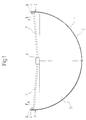
- Fig. 1 shows the schematic representation of a in cross section semicircular trough 1, for example, from consists of a metallic tub and on the inside with a movable relative to the trough 1 perpendicular to the plane of the drawing Inner wall 2 is provided.
- the inner trough wall 2 can be from a in the transport direction circulating, troughed endless belt, which in particular has a thickness of approximately 5 mm.
- the Inner trough wall 2 is at least slightly flexible Made of material that is deformable under pressure is.
- the inner wall of the trough is located in the area of the upper edges 3 of the trough 1 2 emerges essentially vertically upwards, so that the outer sides of the inner trough wall 2 each in a strip Area 4 above the upper edges 3 of the trough 1 exposed.
- a partition 5 which consists of a comparatively hard material, for example made of stainless steel exists and an adapted to the trough cross section, essentially also has semicircular circumferential line.
- the semicircle radius of the semicircular trough cross section or the semicircular circumferential line of the partition 5 can approximately between 600 mm and 900 mm, in particular approximately 750 mm.
- each of the bracket 6 perpendicular to Direction of transport to one of the strip-shaped areas 4 extend.
- the spring bars 7 each provided with a clamping element 8, which each for gripping the strip-shaped areas 4 or upper edges of the inner trough wall 2 is designed.
- the clamping elements 8 can be designed so that the inner wall of the trough 2 can be threaded into this and threaded into this Condition is kept self-locking. Furthermore it is possible, the clamping elements 8 with an actuating mechanism to open and close them.
- the size of the clamping or tensile force lies, for example, in a range between 50 kg and 300 kg, in particular between 100 kg and 200 kg.
- FIG. 1 is only intended to be schematic illustrate the principle of operation according to the invention and therefore does not contain any design details.
- FIG. 2a shows one in the transport direction of the inner wall 2 of the trough vertical section through that area of a Device according to the invention, in which the partition 5 in the Trough inner wall 2 is pressed.
- FIG. 2b essentially corresponds to FIG. 2a with the difference, that the narrow side 9 'of the partition 5' here as roof-shaped edge is formed, which is just like the edge 9 provided with the radius according to FIG. 2a is special presses well into the elastic partition 2 and thus one reliable connection between partition 5 'and inner trough wall 2 manufactures.
- Fig. 3 shows the schematic representation of one with the inner wall of the trough 2 coupled clamping element 12, which on a Spring rod 7 is arranged according to FIG. 1.
- the spring bar 7 is shown in FIG. 1 with the partition 5 coupled and exercises in the position shown in Fig. 3 a pulling force in the direction of arrow A.
- the spring bar 7 At its end facing the inner trough wall 2 is the spring bar 7 provided with a downwardly extending tab 13, on which a clamping jaw 14 about an axis 15 is pivotally mounted.
- the bearing 15 is with one provided spring element, not shown, which the jaws 14 clockwise in the direction of arrow B.
- a counter bracket 16 is attached, which has a contact surface 17 which is on the Jaws 14 opposite side of the upper end region the inner trough wall 2 is located.
- the inner wall of the trough 2 is under slight deformation around the section facing it of the partition circumference 21 stretched, whereby the Narrow side of the partition 5 in the trough inner wall 2 accordingly 2a and 2b and a mechanically stable and adjacent cells sealing against each other created between trough inner wall 2 and partition wall 5 becomes.
- Suitable facilities for generating the above-mentioned pressure forces are preferably arranged along the trough 1 Devices for inserting or removing the partitions coupled.
- a clamping element shown in Fig. 3 12 and a tensioning device designed as a spring bar 7 is only to be understood as an example; it leaves any other construction engineering training realize these devices.
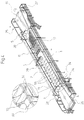
- Fig. 4 shows an overall perspective view of an inventive Device with an elongated trough 1, the one end with a filling area 24 and at provided at its other end with a discharge area 25 and is a continuous between the filling area 24 and Discharge area 25 has transportable inner wall 2.
- the inner trough wall 2 is from a in the transport direction encircling, troughed endless belt formed on the two Ends of the device shown each around a conveyor roller 26, 27 is guided.
- an insertion device 28 for insertion provided by partitions 5 in the trough 1.
- a removal device 29, 30 provided by means of the in the trough 1 located partition walls 5 can be removed from this.
- the devices 28, 29, 30 can preferably be variable Positions can be stationed along the trough 1 so as to Insertion or removal of partitions 5 variable to the adapt the type of cheese to be produced.
- the devices 28, 29, 30 each have a swivel device to pivot the inserted or removed Partitions 5, wherein the pivoting device pivots the partition walls 5 by 90 ° from the transport position in a return position or vice versa.
- a return transport device 31 for from the removal devices 29, 30 removed and from the insertion device 28 partitions to be used in turn 5.
- the return transport device 31 is designed so that the Partitions 5 returned against the direction of transport extend vertically and parallel to the longitudinal direction of the trough 1.
- washing device for the partitions 5 provided, which during the return transport process causes a cleaning process.
- the Trough 1 Between the arranged in the central area of the trough 1 The removal device 29 and the discharge area 25 is the Trough 1 provided with a cutting device 32 with which the after the coagulation process, the cheese is no longer flowable can be cut to curd.
- Fig. 4 is in filling device essentially formed by two filling tubes 34 so arranged that the filling process is already in cells 33 formed takes place (see detailed illustration). On this way the formation of an inlet sump between the conveyor roller 26 and the rearmost in the transport direction Partition 5 avoided, which to those already mentioned above Advantages leads.
- the partitions 5 introduced into the trough 1 can either through the removal device 29 in the central region of the Trough 1 are removed or until the end of trough 1 with the inner trough wall 2 remain coupled.
- the two types separating partition 5 to the trough to run through, for example, to mix the varieties during that caused by the cutter 32 To prevent cutting.
- a rigid and not Removable partition 35 is provided, which each in Direction of transport forwardmost cell 33 on its in the conveying direction front side closes.
- this rigid partition 35 it becomes possible to generate the Cheese mass by means of a discharge tube 36 from the respective in To convey the forward direction of the cell 33 without a discharge sump forms.
- a discharge sump can also be used be provided if the rigid partition 35 is not provided becomes.
- the device according to the invention can thus be simple Way individually to those required for a particular type of cheese Production process to be adjusted because of the partitions 5 in the simplest way at any position in the Trough 1 can be used or removed from it.
- the device according to the invention has those already described Advantages in terms of reduced water consumption and the reduced risk of contamination, whereby at the same time a reliable functionality of the overall device due to the stable connection between partitions 5 and inner trough wall 2 remains guaranteed.
Landscapes
- Life Sciences & Earth Sciences (AREA)
- Animal Husbandry (AREA)
- Environmental Sciences (AREA)
- Dairy Products (AREA)
Description
- Fig. 1
- einen senkrecht zur Transportrichtung verlaufenden Vertikalschnitt einer erfindungsgemäßen Vorrichtung,
- Fig. 2a und b
- unterschiedliche Ausführungsformen von in die Troginnenwand eingedrückten Trennwänden,
- Fig. 3
- eine mögliche Ausführungsform einer erfindungsgemäß verwendbaren Spannvorrichtung, und
- Fig. 4
- die perspektivische Gesamtansicht einer Ausführungsform einer erfindungsgemäßen Vorrichtung.
Claims (16)
- Vorrichtung zum Gewinnen von Käsemasse aus Milch mit einem langgestreckten Trog (1), der an seinem einen Ende mit einem Einfüllbereich (24) und an seinem anderen Ende mit einem Austragsbereich (25) versehen ist und eine zumindest im wesentlichen kontinuierlich zwischen Einfüll- (24) und Austragsbereich (25) transportierbare Innenwand (2) aufweist, wobei das Trogvolumen durch eine Anzahl von dem Trogquerschnitt angepaßten, mit der Innenwand (2) koppel- und gemeinsam mit dieser bewegbaren Trennwänden (5, 5') in in Längsrichtung aufeinanderfolgende Zellen unterteilbar ist,
dadurch gekennzeichnet,
daß zur Erzeugung einer mechanisch stabilen und benachbarte Zellen (10, 11, 33) gegeneinander abdichtenden Verbindung zwischen einander zugewandten Bereichen von Troginnenwand (2) und Trennwand (5, 5') jeder Trennwand (5, 5') eine Spannvorrichtung (6, 7, 8, 12) zugeordnet ist, die sowohl an der zugeordneten Trennwand (5, 5') als auch an der Troginnenwand (2) angreift und mittels der die aus nachgiebigem Material bestehende Troginnenwand (2) unter geringfügiger Verformung um den ihr zugewandten Teilbereich des Trennwandumfangs (21) spannbar ist. - Vorrichtung nach Anspruch 1,
dadurch gekennzeichnet,
daß zur Aufnahme von durch unterschiedliche Füllstände benachbarter Zellen (10, 11, 33) erzeugten Querkräften der durch die Spannvorrichtung (6, 7, 8, 12) bewirkte Anpreßdruck zwischen Troginnenwand (2) und Trennwand (5, 5') einer Gewichtskraft in einem Bereich zwischen 50 kg und 300 kg, insbesondere zwischen 100 kg und 200 kg entspricht. - Vorrichtung nach einem der vorhergehenden Ansprüche,
dadurch gekennzeichnet,
daß die Trennwände (5, 5') an ihren der Troginnenwand (2) zugewandten Schmalseiten (9, 9') mit einem Radius oder einer dachförmigen Kante versehen sind, und/oder daß alle Trennwände (5, 5') identisch ausgebildet sind. - Vorrichtung nach einem der vorhergehenden Ansprüche,
dadurch gekennzeichnet,
daß die Spannvorrichtung (6, 7, 8, 12) an der Trennwand (5, 5') angebracht ist. - Vorrichtung nach einem der vorhergehenden Ansprüche,
dadurch gekennzeichnet,
daß die Spannvorrichtung (6, 7, 8, 12) zumindest ein insbesondere als Federstab (7) ausgebildetes Federelement aufweist, das vor der Kopplung mit der Troginnenwand (2) vorspannbar und bei Kopplung der Troginnenwand (2) unter teilweiser Entspannung desselben zur Erzeugung der erforderlichen Spannkraft geeignet ist. - Vorrichtung nach Anspruch 5,
dadurch gekennzeichnet,
daß zwei im Bereich der beiden einander gegenüberliegenden oberen Ränder (4) der Troginnenwand (2) endende Federstäbe (7) mit jeweils einem Klemmelement (8, 12) zum Greifen dieser Ränder (4) verbunden sind. - Vorrichtung nach Anspruch 6,
dadurch gekennzeichnet,
daß die Troginnenwand (2) in die Klemmelemente (8, 12) einfädelbar und in diesen im eingefädelten Zustand selbsthemmend gehalten ist, und/oder daß die Klemmelemente (8, 12) mit einem Betätigungsmechanismus zum Öffnen und Schließen derselben versehen sind. - Vorrichtung nach einem der vorhergehenden Ansprüche,
dadurch gekennzeichnet,
daß die Troginnenwand (2) quer zur Transportrichtung verstärkt ist, aus zumindest geringfügig elastisch verformbarem Kunststoff, insbesondere aus PVC besteht, mit einem Längs- und/oder Quergewebe versehen ist, und/oder aus einem in Transportrichtung umlaufenden, gemuldeten Endlosband gebildet ist, welches insbesondere eine Stärke von ungefähr 5 mm aufweist. - Vorrichtung nach einem der vorhergehenden Ansprüche,
dadurch gekennzeichnet,
daß der Trog (1) einen im wesentlichen halbkreisförmigen Querschnitt und die Trennwände (5, 5') eine entsprechende, ebenfalls im wesentlichen halbkreisförmige Umfangslinie (21) aufweisen, wobei insbesondere der Halbkreisradius ungefähr zwischen 600 mm und 900 mm, insbesondere in etwa 750 mm beträgt. - Vorrichtung nach einem der vorhergehenden Ansprüche,
dadurch gekennzeichnet,
daß die Trennwände (5, 5') zumindest im wesentlichen aus Metall, insbesondere aus Edelstahl bestehen. - Vorrichtung nach einem der vorhergehenden Ansprüche,
dadurch gekennzeichnet,
daß der Einfüllbereich (24) im Bereich bereits durch Trennwände (5, 5') gebildeter Zellen (10, 11, 33) angeordnet ist, so daß die Zellen (10, 11, 33) direkt mit Milch befüllbar sind, und/oder daß der Austragsbereich (25) im Bereich durch Trennwände (5, 35) gebildeter Zellen (10, 11, 33) angeordnet ist, so daß die Käsemasse direkt aus den Zellen (10, 11, 33) entnehmbar ist. - Vorrichtung nach einem der vorhergehenden Ansprüche,
dadurch gekennzeichnet,
daß zumindest im Einfüllbereich (24) eine Vorrichtung (28) zum Einsetzen der Trennwände (5, 5') und zumindest im Austragsbereich (25) eine Vorrichtung (30) zum Entnehmen der Trennwände (5, 5') vorgesehen ist. - Vorrichtung nach einem der vorhergehenden Ansprüche,
dadurch gekennzeichnet,
daß die Trennwände (5, 5') an unterschiedlichen Positionen entlang der Längserstreckung des Trogs (1) entnehmbar sind. - Vorrichtung nach einem der vorhergehenden Ansprüche,
dadurch gekennzeichnet,
daß neben dem Trog (1) eine sich parallel zu dessen Längsrichtung erstreckende Rücktransportvorrichtung (31) für beispielsweise im Austragsbereich (25) entnommene und im Einfüllbereich (24) einzusetzende Trennwände (5, 5') vorgesehen ist, wobei sich insbesondere die in der Rücktransportvorrichtung (31) beförderten Trennwände (5, 5') vertikal und parallel zur Längsrichtung des Trogs (1) erstrecken. - Vorrichtung nach einem der Ansprüche 12 bis 14,
dadurch gekennzeichnet,
daß die Vorrichtungen (28, 29, 30) zum Einsetzen bzw. Entnehmen der Trennwände (5, 5') mit einer Schwenkvorrichtung zum Verschwenken der Trennwände (5, 5') aus der Rückförder- in die Transportposition bzw. umgekehrt, insbesondere um 90° versehen sind. - Vorrichtung nach einem der Ansprüche 14 oder 15,
dadurch gekennzeichnet,
daß die Rücktransportvorrichtung (31) mit einer Wascheinrichtung für die Trennwände (5, 5') versehen ist.
Applications Claiming Priority (2)
| Application Number | Priority Date | Filing Date | Title |
|---|---|---|---|
| DE19531601A DE19531601A1 (de) | 1995-08-28 | 1995-08-28 | Vorrichtung zum Gewinnen von Käsemasse |
| DE19531601 | 1995-08-28 |
Publications (2)
| Publication Number | Publication Date |
|---|---|
| EP0761092A1 EP0761092A1 (de) | 1997-03-12 |
| EP0761092B1 true EP0761092B1 (de) | 2001-03-14 |
Family
ID=7770577
Family Applications (1)
| Application Number | Title | Priority Date | Filing Date |
|---|---|---|---|
| EP96109988A Expired - Lifetime EP0761092B1 (de) | 1995-08-28 | 1996-06-20 | Vorrichtung zum Gewinnen von Käsemasse |
Country Status (3)
| Country | Link |
|---|---|
| EP (1) | EP0761092B1 (de) |
| DE (2) | DE19531601A1 (de) |
| DK (1) | DK0761092T3 (de) |
Families Citing this family (3)
| Publication number | Priority date | Publication date | Assignee | Title |
|---|---|---|---|---|
| DE19627837A1 (de) * | 1996-07-10 | 1998-01-15 | Alpma Alpenland Masch | Verfahren und Vorrichtung zur Gewinnung von Käsemasse |
| DE19746409A1 (de) * | 1997-10-21 | 1999-04-22 | Alpma Alpenland Masch | Vorrichtung zum Gewinnen von Käsemasse aus Milch |
| DE102012220325A1 (de) | 2012-11-08 | 2014-05-08 | Alpma Alpenland Maschinenbau Gmbh | Koagulationsbehälter |
Family Cites Families (5)
| Publication number | Priority date | Publication date | Assignee | Title |
|---|---|---|---|---|
| US3394011A (en) * | 1964-01-03 | 1968-07-23 | Swift & Co | Continuous production of cheese curd |
| FR1597616A (de) * | 1968-11-18 | 1970-06-29 | ||
| DE2406616C3 (de) * | 1974-02-12 | 1983-12-29 | Alpma Alpenland Maschinenbau Hain & Co KG, 8093 Rott | Vorrichtung zum kontinuierlichen Gewinnen von Käsemasse aus vorbehandelter Milch |
| DE2451617C2 (de) * | 1974-10-30 | 1985-05-02 | Alpma Alpenland Maschinenbau Hain & Co KG, 8093 Rott | Vorrichtung zum kontinuierlichen Gewinnen von Käsemasse aus vorbehandelter Milch |
| DE3038661C2 (de) * | 1980-10-13 | 1983-01-20 | Alpma Alpenland Maschinenbau Hain & Co KG, 8093 Rott | Vorrichtung zum kontinuierlichen Gewinnen von Käsemasse |
-
1995
- 1995-08-28 DE DE19531601A patent/DE19531601A1/de not_active Withdrawn
-
1996
- 1996-06-20 DK DK96109988T patent/DK0761092T3/da active
- 1996-06-20 EP EP96109988A patent/EP0761092B1/de not_active Expired - Lifetime
- 1996-06-20 DE DE59606577T patent/DE59606577D1/de not_active Expired - Lifetime
Also Published As
| Publication number | Publication date |
|---|---|
| DE59606577D1 (de) | 2001-04-19 |
| DE19531601A1 (de) | 1997-03-06 |
| EP0761092A1 (de) | 1997-03-12 |
| DK0761092T3 (da) | 2001-04-17 |
Similar Documents
| Publication | Publication Date | Title |
|---|---|---|
| DE102007032341B4 (de) | Förderband eines Kettenförderers mit innovativen Mitnehmergliedern | |
| DE3412275C2 (de) | Pulverbeschichtungskabine | |
| DE102007062373B4 (de) | Lebensmittelpresse, insbesondere Knoblauchpresse | |
| EP0606530A1 (de) | Schlauchgurtförderer | |
| DE102021112517B3 (de) | Trennvorrichtung zum Trennen von Portionen aus mit Lebensmittel-Masse befüllten, länglichen Hüllen sowie betreffendes Verfahren | |
| DE102009040923B3 (de) | Vorrichtung und Verfahren zur Herstellung einer Wurstschnecke | |
| EP0761092A1 (de) | Vorrichtung zum Gewinnen von Käsemasse | |
| DE60220445T2 (de) | Biegevorrichtung für profile wie rundbetonstahlstäbe oder ähnliche | |
| DE102008061327A1 (de) | Extruderanordnung | |
| WO2009080293A1 (de) | Verpackungsmaschine | |
| DE2823732C2 (de) | Vorrichtung zum Ausschäumen von langgestreckten Hohlprofilkörpern, insbesondere Rolladenstäben | |
| DE3020922C2 (de) | Vorrichtung zum bogenförmigen Umformen eines aus einem thermoplastischen Kunststoff bestehenden Profilstrangabschnitts mit Hohlkammern | |
| DE2603615A1 (de) | Verfahren und vorrichtung zur buendelung von kunststoffgitter-roehren | |
| DE102005056374B4 (de) | Riemen zum Transportieren von Gefäßen und Verfahren zum Herstellen eines Riemens | |
| EP0910943A1 (de) | Vorrichtung zum Gewinnen von Käsemasse aus Milch | |
| CH669588A5 (de) | ||
| DE2710512C3 (de) | Anlage zur Herstellung von aus gleichen Formenteilen zusammengesetzten Gießformen | |
| EP0166081A2 (de) | Vorrichtung zur Druckbehandlung von Fleisch | |
| DE10241334B4 (de) | Luftreinigungsvorrichtung für Abschwartungs-, Enthäutungs- und/oder Entvliesmaschinen | |
| DE4024936C2 (de) | Verfahren und Vorrichtung zum Biegen von Doppelwandrohren | |
| DE1914617C3 (de) | Strangpresse für schmelzbare oder plastifizierbare Stoffe, insbesondere Kunststoffe | |
| DE102019006557B3 (de) | Zerkleinerungstrommel für eine Schneid- und Separiervorrichtung (Zuführkanal) | |
| DE8627665U1 (de) | Aus einem Werkstoff spritzbarer Käfig für Wälzlager | |
| DE1058903B (de) | Spreizkern zur Herstellung von Hohlkoerpern aus Beton od. dgl. | |
| DD248046A5 (de) | Vorrichtung zum umsetzen von formstuecken weicher konsistenz |
Legal Events
| Date | Code | Title | Description |
|---|---|---|---|
| PUAI | Public reference made under article 153(3) epc to a published international application that has entered the european phase |
Free format text: ORIGINAL CODE: 0009012 |
|
| AK | Designated contracting states |
Kind code of ref document: A1 Designated state(s): DE DK FR IT |
|
| 17P | Request for examination filed |
Effective date: 19970421 |
|
| 17Q | First examination report despatched |
Effective date: 19990707 |
|
| RAP1 | Party data changed (applicant data changed or rights of an application transferred) |
Owner name: ALPMA ALPENLAND MASCHINENBAU GMBH |
|
| GRAG | Despatch of communication of intention to grant |
Free format text: ORIGINAL CODE: EPIDOS AGRA |
|
| GRAG | Despatch of communication of intention to grant |
Free format text: ORIGINAL CODE: EPIDOS AGRA |
|
| GRAH | Despatch of communication of intention to grant a patent |
Free format text: ORIGINAL CODE: EPIDOS IGRA |
|
| GRAH | Despatch of communication of intention to grant a patent |
Free format text: ORIGINAL CODE: EPIDOS IGRA |
|
| GRAA | (expected) grant |
Free format text: ORIGINAL CODE: 0009210 |
|
| ITF | It: translation for a ep patent filed | ||
| AK | Designated contracting states |
Kind code of ref document: B1 Designated state(s): DE DK FR IT |
|
| REG | Reference to a national code |
Ref country code: DK Ref legal event code: T3 |
|
| REF | Corresponds to: |
Ref document number: 59606577 Country of ref document: DE Date of ref document: 20010419 |
|
| ET | Fr: translation filed | ||
| PLBE | No opposition filed within time limit |
Free format text: ORIGINAL CODE: 0009261 |
|
| STAA | Information on the status of an ep patent application or granted ep patent |
Free format text: STATUS: NO OPPOSITION FILED WITHIN TIME LIMIT |
|
| 26N | No opposition filed | ||
| PGFP | Annual fee paid to national office [announced via postgrant information from national office to epo] |
Ref country code: DK Payment date: 20090611 Year of fee payment: 14 |
|
| REG | Reference to a national code |
Ref country code: DK Ref legal event code: EBP |
|
| PG25 | Lapsed in a contracting state [announced via postgrant information from national office to epo] |
Ref country code: DK Free format text: LAPSE BECAUSE OF NON-PAYMENT OF DUE FEES Effective date: 20100630 |
|
| REG | Reference to a national code |
Ref country code: FR Ref legal event code: PLFP Year of fee payment: 20 |
|
| PGFP | Annual fee paid to national office [announced via postgrant information from national office to epo] |
Ref country code: FR Payment date: 20150619 Year of fee payment: 20 Ref country code: IT Payment date: 20150622 Year of fee payment: 20 |
|
| PGFP | Annual fee paid to national office [announced via postgrant information from national office to epo] |
Ref country code: DE Payment date: 20150828 Year of fee payment: 20 |
|
| REG | Reference to a national code |
Ref country code: DE Ref legal event code: R071 Ref document number: 59606577 Country of ref document: DE |