EP0760750B1 - Radaufhängung mit querblattfederung - Google Patents
Radaufhängung mit querblattfederung Download PDFInfo
- Publication number
- EP0760750B1 EP0760750B1 EP96903860A EP96903860A EP0760750B1 EP 0760750 B1 EP0760750 B1 EP 0760750B1 EP 96903860 A EP96903860 A EP 96903860A EP 96903860 A EP96903860 A EP 96903860A EP 0760750 B1 EP0760750 B1 EP 0760750B1
- Authority
- EP
- European Patent Office
- Prior art keywords
- leaf spring
- fact
- wheel
- wheel suspension
- suspension
- Prior art date
- Legal status (The legal status is an assumption and is not a legal conclusion. Google has not performed a legal analysis and makes no representation as to the accuracy of the status listed.)
- Expired - Lifetime
Links
- 239000000725 suspension Substances 0.000 title claims description 61
- 239000002131 composite material Substances 0.000 claims description 9
- 239000004593 Epoxy Substances 0.000 claims description 2
- 239000003365 glass fiber Substances 0.000 claims description 2
- 238000007373 indentation Methods 0.000 claims description 2
- 229920001169 thermoplastic Polymers 0.000 claims description 2
- 239000004416 thermosoftening plastic Substances 0.000 claims description 2
- 230000008878 coupling Effects 0.000 claims 2
- 238000010168 coupling process Methods 0.000 claims 2
- 238000005859 coupling reaction Methods 0.000 claims 2
- 239000004033 plastic Substances 0.000 claims 2
- 241000531908 Aramides Species 0.000 claims 1
- 229920003235 aromatic polyamide Polymers 0.000 claims 1
- 239000000835 fiber Substances 0.000 description 6
- 229920002492 poly(sulfone) Polymers 0.000 description 4
- 229920002647 polyamide Polymers 0.000 description 4
- 229920001601 polyetherimide Polymers 0.000 description 4
- 229910000831 Steel Inorganic materials 0.000 description 2
- 239000006096 absorbing agent Substances 0.000 description 2
- 230000015572 biosynthetic process Effects 0.000 description 2
- 238000010276 construction Methods 0.000 description 2
- 238000006073 displacement reaction Methods 0.000 description 2
- 230000000694 effects Effects 0.000 description 2
- 238000004519 manufacturing process Methods 0.000 description 2
- 239000011159 matrix material Substances 0.000 description 2
- 229920006393 polyether sulfone Polymers 0.000 description 2
- 230000035939 shock Effects 0.000 description 2
- 239000003381 stabilizer Substances 0.000 description 2
- 239000010959 steel Substances 0.000 description 2
- 230000008719 thickening Effects 0.000 description 2
- 241001247986 Calotropis procera Species 0.000 description 1
- 229920012266 Poly(ether sulfone) PES Polymers 0.000 description 1
- 239000004952 Polyamide Substances 0.000 description 1
- 239000004697 Polyetherimide Substances 0.000 description 1
- 239000004734 Polyphenylene sulfide Substances 0.000 description 1
- 238000010521 absorption reaction Methods 0.000 description 1
- 230000006978 adaptation Effects 0.000 description 1
- AZDRQVAHHNSJOQ-UHFFFAOYSA-N alumane Chemical group [AlH3] AZDRQVAHHNSJOQ-UHFFFAOYSA-N 0.000 description 1
- 239000004760 aramid Substances 0.000 description 1
- 229920006231 aramid fiber Polymers 0.000 description 1
- 230000002301 combined effect Effects 0.000 description 1
- 230000001419 dependent effect Effects 0.000 description 1
- 238000011161 development Methods 0.000 description 1
- 230000018109 developmental process Effects 0.000 description 1
- 238000005516 engineering process Methods 0.000 description 1
- 230000002349 favourable effect Effects 0.000 description 1
- 238000005457 optimization Methods 0.000 description 1
- 229920000069 polyphenylene sulfide Polymers 0.000 description 1
- 230000000750 progressive effect Effects 0.000 description 1
- 230000002787 reinforcement Effects 0.000 description 1
- 238000005096 rolling process Methods 0.000 description 1
- 239000007787 solid Substances 0.000 description 1
- 238000003860 storage Methods 0.000 description 1
Images


Classifications
-
- F—MECHANICAL ENGINEERING; LIGHTING; HEATING; WEAPONS; BLASTING
- F16—ENGINEERING ELEMENTS AND UNITS; GENERAL MEASURES FOR PRODUCING AND MAINTAINING EFFECTIVE FUNCTIONING OF MACHINES OR INSTALLATIONS; THERMAL INSULATION IN GENERAL
- F16F—SPRINGS; SHOCK-ABSORBERS; MEANS FOR DAMPING VIBRATION
- F16F1/00—Springs
- F16F1/36—Springs made of rubber or other material having high internal friction, e.g. thermoplastic elastomers
- F16F1/366—Springs made of rubber or other material having high internal friction, e.g. thermoplastic elastomers made of fibre-reinforced plastics, i.e. characterised by their special construction from such materials
- F16F1/368—Leaf springs
-
- B—PERFORMING OPERATIONS; TRANSPORTING
- B60—VEHICLES IN GENERAL
- B60G—VEHICLE SUSPENSION ARRANGEMENTS
- B60G11/00—Resilient suspensions characterised by arrangement, location or kind of springs
- B60G11/02—Resilient suspensions characterised by arrangement, location or kind of springs having leaf springs only
- B60G11/08—Resilient suspensions characterised by arrangement, location or kind of springs having leaf springs only arranged substantially transverse to the longitudinal axis of the vehicle
-
- B—PERFORMING OPERATIONS; TRANSPORTING
- B60—VEHICLES IN GENERAL
- B60G—VEHICLE SUSPENSION ARRANGEMENTS
- B60G7/00—Pivoted suspension arms; Accessories thereof
- B60G7/001—Suspension arms, e.g. constructional features
-
- B—PERFORMING OPERATIONS; TRANSPORTING
- B60—VEHICLES IN GENERAL
- B60G—VEHICLE SUSPENSION ARRANGEMENTS
- B60G2200/00—Indexing codes relating to suspension types
- B60G2200/10—Independent suspensions
-
- B—PERFORMING OPERATIONS; TRANSPORTING
- B60—VEHICLES IN GENERAL
- B60G—VEHICLE SUSPENSION ARRANGEMENTS
- B60G2202/00—Indexing codes relating to the type of spring, damper or actuator
- B60G2202/10—Type of spring
- B60G2202/11—Leaf spring
-
- B—PERFORMING OPERATIONS; TRANSPORTING
- B60—VEHICLES IN GENERAL
- B60G—VEHICLE SUSPENSION ARRANGEMENTS
- B60G2202/00—Indexing codes relating to the type of spring, damper or actuator
- B60G2202/10—Type of spring
- B60G2202/11—Leaf spring
- B60G2202/114—Leaf spring transversally arranged
Definitions
- the invention relates to a wheel suspension for a vehicle axle with two wheels, with a transverse leaf suspension according to the preamble of independent claim 1.
- wheel suspensions with only one steel transverse leaf spring are for Both wheels of an axle are known for a relatively simple structure, however so that precise wheel guidance is not possible.
- wheel suspensions with only one steel transverse leaf spring are for Both wheels of an axle are known for a relatively simple structure, however so that precise wheel guidance is not possible.
- a lightweight composite leaf spring known, which however no wheel guidance takes over, so here is a relatively complex, many elements comprehensive suspension is required.
- Such need previous Constructions also have a relatively large construction volume.
- a wheel suspension according to Claim 1 By designing the tight and precisely held wheel guiding Composite transverse leaf spring with its two-point bearing D and the anisotropic elastic linkage G on the wheel carrier, which has defined and coordinated stiffness in the have three directions X, Y, Z, in combination with one Wheel guiding element includes all wheel forces including drive and braking torques and optimum driving characteristics with the simplest possible effort and with one minimum number of suspension elements reached. At the same time weight and space requirements for the entire wheel suspension are also significantly reduced.
- the dependent claims relate to advantageous developments of the invention particularly light, inexpensive to manufacture and assemble suspensions, which result in particularly advantageous driving properties and suspension properties and with which the chassis is optimally adjusted to the desired operating conditions can be.
- the wheel guide element can act as a wheel-guiding damper leg be trained and thereby a particularly space-saving and simple suspension form.
- the wheel guide element can also be designed as a triangular wishbone, with which e.g. a particularly low overall height for front axles of vehicles with low front sections is made possible.
- Figure 1 shows schematically an inventive suspension in the front and Side view with a cross leaf spring 10, which with an anisotropic elastic joint 30 (or 50 in Fig. 7) in Articulation point G is connected to a wheel carrier 5 and to a telescopic damper leg 20, which is firmly connected to the wheel carrier 5 and which on Dom Vietnamese E is hinged to the chassis or body of the vehicle.
- the cross leaf spring 10 is mounted in the two-point bearings 15 with axis of rotation D on the chassis. All forces and moments acting on the wheel 3 are combined Effect of these two wheel guide elements 10 and 20 added: Vertical forces FZ in the vertical direction Z are caused by the leaf spring 10 with a large deflection dZ (or with a low spring rate cZ) cushioned.
- the Cross leaf spring is designed very stiff in the X direction with a very high spring rate cX, see above that the ratio of the spring rates cX / cZ is at least 15, preferably about 20 to 40 is.
- a very small deflection dX in the longitudinal direction can Compensation of the rolling hardness of the steel belt tire can be set or approved.
- a decisive advantage has been achieved: there is no additional trailing arm here any kind of support for longitudinal forces FX more needed, like this has always been necessary.
- the deflection dY is kept to a minimum by suitably taut Bracket in the two-point bearing D or 15 (see Fig. 5).
- Drive and braking torques Ma and Mb are through the cross leaf spring 10 and the damper 20th supported. Suitable dimensions are given at the end.
- the linkage G is further explained in relation to FIG. 7.
- FIG. 2a, b, c shows in three views a front axle with front-wheel drive and with one Carrier 40 (Fig. 2b) as a light subframe on which the two-point bearing D, 15 of the cross leaf spring 10 is fastened to the brackets 41.
- a drive unit 4 e.g. an electric motor with gearbox and differential or a parallel hybrid unit
- the steering gear of a steering 6 is also at points 42 fixed to the carrier 40.
- This carrier 40 can with the whole suspension and components attached to it can be assembled, adjusted and checked separately. Then this module can be easily and quickly attached to the chassis or body of the Vehicle.
- the horizontal lengths of the middle part 11 and outer parts 12 are L1 and L2.
- a transverse leaf spring 10 in Combination with the two wheel-guiding damper legs 20 on one axle e.g. at least two lower triangular wishbones, two coil springs and a stabilizer a previous McPherson strut suspension. This gives one particularly simple, easy and inexpensive solution.
- Figure 3a, b, c shows a rear axle suspension with damper legs 20, which in an angle W1 of e.g. 8 ° - 12 ° to the vertical Z are arranged.
- the cross leaf spring 10 here is inclined slightly backwards at an angle W2 of the central plane M to the horizontal X of e.g. 1 ° - 5 °.
- This effect can also be carried out analogously to an execution with triangular wishbones as a wheel guide element (according to FIG. 5) by a Design with the angles W1 and W2 can be realized.
- the extremely space-saving design of this The simple wheel suspension according to the invention can also be seen from the drawing Interior boundary 8 (Fig. 2c, 3c). A particularly simple one is shown in FIG. 3a and light training shown, in which the wheel carrier 5 with a Brake shield 7 of a drum brake is integrally formed together.
- the wheel carrier with brake plate can preferably be manufactured as an aluminum part, e.g. be cast, and have holes for brake shoes and lines.
- the the corresponding brake drum can also be integrated in one piece in the wheel rim his.
- leaf spring 10 here substitutes two lower wishbones, two springs and possibly a stabilizer of a previously usual wheel suspension.
- Figures 5 and 6 show examples of the very precise and tight two-point bearing the cross leaf spring 10 in the bearings 15 with axis of rotation D. Since the horizontal Length L1 of the middle part of the leaf spring between the bearings 15, D (see Fig. 2a and 10) slightly changed by dLl of e.g. +/- 1 mm, this must be in the Storage 15 can be compensated or absorbed elastically. Preferably this is set so that the occurring maximum elastic transverse displacement dY1 is not greater than the maximum change in length dLl of the spring, i.e. that dY1 e.g. 1 - 2 mm, but at most 3 mm.
- the bearing pivot D if possible lie in the center line or center plane M of the leaf spring.
- the leaf spring should not be weakened in the bearing points. All fibers should be as continuous as possible. This is achieved here by using a cuff 17 Large pivot 16 is glued to the leaf spring. The pivot 16 with the axes D lie in the middle of the sheet M. A sketched other version with a The axis of rotation 16a has a distance dm between D and M, which is, however if possible, it should not be greater than the thickness h of the cross leaf spring.
- FIG. 6 shows an embodiment with an integrated cylindrical thickening 18 Leaf spring, which defines the axis of rotation D and which is held in the bearing 15 is.
- This thickening is made from the same composite material as the leaf spring in addition to the continuous layering of the leaf spring 10 continuous longitudinal fibers 48 applied.
- dY1 the necessary minimal flexibility dY1 through appropriate design and configuration of leaf spring at this point and of the associated bearing part on the chassis set.
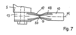
- FIG. 7 shows articulations by means of anisotropic elastic joints 50 at the ends of the leaf spring 10 with an articulation point G.
- the hinge point G is placed in the leaf center line M of the leaf spring (Fig. 7).
- the linkage G must be designed so that the necessary movements of the Wheel carrier 5 are executable without significant torsional forces.
- the Linkage G to the wheel carrier 5 as a flexible point in the form of an indentation 47 in the cross leaf spring is molded.
- the longitudinal fibers 48 are large Part laid continuously so that the required strength is also complete here preserved.
- the end 13 of the leaf spring is connected to the wheel carrier 5 e.g. by Screw connection firmly connected.
- the dimensioning of the flexible point 47 is like this chosen that the specified spring rates cX, cZ and deflections dX, dY, dZ be respected.
- the elastic joint 50 or the flexible point 47 can, however, also consist of a connecting part exist, which on the one hand on the leaf spring 10 and on the other hand on the wheel carrier 5th attached, e.g. from a flexible elbow.
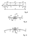
- Figure 8 shows a shape of a transverse leaf spring 10 in the unloaded state, which in the Middle part 11 between the bearing points D is slightly curved or almost straight and whose outer parts 12 are bent downward towards the articulation points G.
- This shape is designed so that for the intended load in the vehicle Total deflection dZ, i.e. the entire spring area, essentially approximately evenly lies above and below the horizontal. With medium vehicle load the outer parts 12 are then essentially horizontal: position 12b.
- the Spring shape is designed so that the change in length dLl in the middle remains as small as possible (see Figure 5).
- a particularly simple version has a constant, relatively large rectangular cross-section with dimensions as indicated below. To increase the safety against breakage, the spring in the middle part 11 can also be designed somewhat thicker.
- the transverse leaf spring 10 points in the vehicle center plane M2 has a deflection range dZ2.
- the spring characteristic cZ at the pivot point G can be influenced, which is further illustrated with reference to FIGS. 9 and 10.
- Figure 9 shows additional stops 36, 37 in the central part 11 of the cross leaf spring, with which the deflections and thus also the change in length dLl are limited can and with which a targeted influencing of the spring characteristic is possible.
- the leaf spring should rest on the stops over a large area To avoid peak loads.
- the stops can also be made elastic be, e.g. as a rubber buffer 37. For example, a desired progressive Spring characteristics can be set.
- Figure 10 shows another. Shape of a cross leaf spring 10 with a counter bow 46 in Middle part 11. This can lead to a further enlargement of the free usable space contribute.
- This example also creates space for one Additional suspension 35, which for level control as an adaptation to different Loading conditions of the vehicle can be used.
- This additional spring 35 is e.g. as Air spring formed, which on the chassis or on the carrier 40 (see Figure 2b, 3a), is supported and which the transverse leaf spring 10 e.g. covered with a tape so that this with a force F2 corresponding to the load in the middle upwards can be pressed.
- the cross leaf spring has the following dimensions: overall length L 1000 - 1100 mm Length of middle section L1 400 - 450 mm Length of outer parts L2 300 - 350 mm width b 60 - 100 mm, preferably 70 - 80 mm height H 10 - 20 mm, preferably 12 - 15 mm relationship bra 4 - 8, preferably 5 - 6 Cross sectional area 700 - 1200 mm 2 , preferably 800 - 1000mm 2 Travel dZ 150-200 mm Spring rate cZ 10 - 20 N / mm E-module 30 - 50 kN / mm 2 Deflection area in M2 dZ2 10 - 60 mm Ratio of spring rates: cX / cZ 16 - 60, preferably 20-40
Landscapes
- Engineering & Computer Science (AREA)
- Mechanical Engineering (AREA)
- General Engineering & Computer Science (AREA)
- Vehicle Body Suspensions (AREA)
Description
- Fig. 1
- eine erfindungsgemässe Radaufhängung mit Aufnahme aller einwirkenden Kräfte und Momente,
- Fig. 2
- eine angetriebene Vorderachse mit Dämpferbeinen und Träger-Hilfsrahmen,
- Fig. 3
- eine Hinterachse mit Dämpferbeinen und Bremsnickabstützung,
- Fig. 4
- ein Beispiel mit einem Dreieck-Querlenker als Radführungselement,
- Fig. 5, 6
- Beispiele der Lagerung D der Querblattfeder am Chassis,
- Fig. 7
- ein Beispiel der Anlenkung G der Querblattfeder am Radträger,
- Fig. 8
- eine gebogene Querblattfeder,
- Fig. 9
- eine Querblattfeder mit zusätzlichen Anschlägen,
- Fig. 10
- eine Querblattfeder mit mittigem Gegenbogen und Niveauregulierung.
| Gesamtlänge | L | 1000 - 1100 mm | ||
| Länge Mittelteil | L1 | 400 - 450 mm | ||
| Länge Aussenteile | L2 | 300 - 350 mm | ||
| Breite | b | 60 - 100 mm, | vorzugsweise | 70 - 80 mm |
| Höhe | h | 10 - 20 mm, | vorzugsweise | 12 - 15 mm |
| Verhältnis | b/h | 4 - 8 , | vorzugsweise | 5 - 6 |
| Querschnittsfläche | 700 - 1200 mm2, | vorzugsweise | 800 - 1000mm2 | |
| Federweg | dZ | 150 - 200 mm | ||
| Federrate | cZ | 10 - 20 N/mm | ||
| E-Modul | 30 - 50 kN/mm2 | |||
| Auslenkbereich in M2 | dZ2 | 10 - 60 mm | ||
| Verhältnis der Federraten: | ||||
| cX/cZ | 16 - 60 , | vorzugsweise | 20 - 40 |
- Verbunde mit 40 - 60 Vol% Faseranteil, welcher Faseranteil zu einem grossen Teil in Längsrichtung orientiert sein soll,
- technische Endlosfasern mit proportionalem Dehnungsbereich von mindestens 2%, im speziellen sind dies Glasfasern und Aramidfasern als Verstärkung,
- als Matrixmaterial Epoxy-Prepregs oder Thermoplaste wie Polyphenylensulfid (PPS), Polyethersulfon (PES), Polysulfon (PSU), Polyetherimid (PEI) und Polyamid (PA).
Claims (23)
- Radaufhängung für eine Fahrzeugachse mit zwei Rädern mit einer einteiligen, durchgehenden und radführenden Verbundwerkstoff-Querblattfeder (10), welche aus einem mit grossteils längsorientierten technischen Endlosfasern verstärkten Kunststoff besteht, mit einer Zweipunktlagerung D der Blattfeder am Chassis und mit je einem Radträger an den Blattfederenden, wobei die Blattfederenden (13) mit einer Anlenkung G gelenkig mit den Radträgern (5) verbunden sind und mit je einem Längs- und Querkräfte abstützenden Radführungselement (20, 25), welches den Radträger gelenkig mit dem Chassis verbindet, so dass mit der Querblattfeder (10) und den Radführungselementen alle Radkräfte aufnehmbar sind, dadurch gekennzeichnet, dass die Zweipunktlagerung D eine hohe Steifigkeit in Querrichtung Y aufweist, mit einer Federrate cX der Federung in Fahrrichtung X und einer Federrate cZ in Hochrichtung Z, wobei das Verhältnis der Federraten cX / cZ mindestens 20 beträgt und dass die Anlenkung G als anisotropes elastisches Gelenk (50) ausgebildet ist.
- Radaufhängung nach Anspruch 1, dadurch gekennzeichnet, dass das anisotrope elastische Gelenk als eine flexible Stelle (47) bildende Einbuchtung der Blattfeder ausgebildet ist.
- Radaufhängung nach Anspruch 1, dadurch gekennzeichnet, dass das anisotrope elastische Gelenk aus einem flexiblen Verbindungsteil zwischen Blattfederende (13) und Radträger besteht.
- Radaufhängung nach Anspruch 1, dadurch gekennzeichnet, dass das Radführungselement als radführendes Dämpferbein (20) oder als Dreieck-Querlenker (25) ausgebildet ist.
- Radaufhängung nach Anspruch 1, dadurch gekennzeichnet, dass der Abstand dm des Lagerdrehpunkts D von der Blattfedermittellinie M kleiner ist die Blattfederdicke h.
- Radaufhängung nach Anspruch 1, dadurch gekennzeichnet, dass der Lagerdrehpunkt D in der Blattfedermittellinie M liegt.
- Radaufhängung nach Anspruch 1, dadurch gekennzeichnet, dass die maximale elastische Querverschiebung dY1 der Blattfeder in einem Lagerpunkt D zwischen 1 - 3 mm liegt.
- Radaufhängung nach Anspruch 1, dadurch gekennzeichnet, dass die maximale elastische Querverschiebung dY1 in einem Lagerpunkt D nicht grösser ist als die Längenänderung dL1 des Mittelteils (11) der Blattfeder beim Einfedern.
- Radaufhängung nach Anspruch 1, dadurch gekennzeichnet, dass die Querblattfeder einen Auslenkbereich dZ2 in der Fahrzeugmitte M2 aufweist, mit welchem die Federcharakteristik beeinflussbar ist.
- Radaufhängung nach Anspruch 1, dadurch gekennzeichnet, dass die Aufhängung mit dem Radführungselement einen Winkel W1 zur Vertikalen Z und die Mittelebene M der Querblattfeder einen Winkel W2 zur Horizontalen X aufweist.
- Radaufhängung nach Anspruch 1, dadurch gekennzeichnet, dass der Gelenkpunkt G am Radträger (5) in der Blattfedermittellinie M liegt.
- Radaufhängung nach Anspruch 1, dadurch gekennzeichnet, dass die Blattfeder eine konstante Breite b aufweist.
- Radaufhängung nach Anspruch 1, dadurch gekennzeichnet, dass die Blattfeder im Mittelteil (11) dicker ist als in den Aussenteilen (12).
- Radaufhängung nach Anspruch 1, dadurch gekennzeichnet, dass die Blattfeder Glasfasern und/oder Aramidfasern enthält und einen unidirektionalen Faseranteil von mindestens 45 Vol% aufweist.
- Radaufhängung nach Anspruch 1, dadurch gekennzeichnet, dass die Blattfeder aus Epoxy-Prepregs aufgebaut ist.
- Radaufhängung nach Anspruch 1, dadurch gekennzeichnet, dass die Blattfeder einen Thermoplast wie PPS, PES, PSU, PEI oder PA als Kunststoff enthält.
- Radaufhängung nach Anspruch 17, dadurch gekennzeichnet, dass der Mittelteil (11) der Blattfeder einen Gegenbogen (46) aufweist.
- Radaufhängung nach Anspruch 1, gekennzeichnet durch eine zusätzliche einstellbare Spurstange (32), welche am Radträger angelenkt ist.
- Radaufhängung nach Anspruch 1, gekennzeichnet durch eine niveauregulierende Zusatzfeder (35), welche auf die Mitte der Blattfeder einwirkt.
- Radaufhängung nach Anspruch 1, dadurch gekennzeichnet, dass im mittleren Bereich Anschläge (36, 37) mit definierter Form und/oder Elastizität angeordnet sind, welche die Federcharakteristik der Blattfeder beeinflussen.
- Radaufhängung nach Anspruch 1, dadurch gekennzeichnet, dass die Radträger (5) mit einem Bremsschild (7) einer Trommelbremse zusammen einstückig ausgebildet sind.
- Radaufhängung nach Anspruch 1, dadurch gekennzeichnet, dass sie einen Träger (40) mit Halterungen (41) für die Lagerpunkte D aufweist, welcher als Baueinheit am Chassis montierbar ist und wobei am Träger auch Halterungen für die Lenkung (42) und/oder den Antrieb (43) vorgesehen sind.
- Radaufhängung nach Anspruch 1, dadurch gekennzeichnet, dass die Blattfeder eine zylinderförmige Verdickung (18) aufweist, welche die Drehachse D definiert.
Applications Claiming Priority (4)
| Application Number | Priority Date | Filing Date | Title |
|---|---|---|---|
| CH62495 | 1995-03-06 | ||
| CH624/95 | 1995-03-06 | ||
| CH62495 | 1995-03-06 | ||
| PCT/CH1996/000076 WO1996027507A1 (de) | 1995-03-06 | 1996-03-04 | Radaufhängung mit querblattfederung |
Publications (2)
| Publication Number | Publication Date |
|---|---|
| EP0760750A1 EP0760750A1 (de) | 1997-03-12 |
| EP0760750B1 true EP0760750B1 (de) | 2001-10-10 |
Family
ID=4191348
Family Applications (1)
| Application Number | Title | Priority Date | Filing Date |
|---|---|---|---|
| EP96903860A Expired - Lifetime EP0760750B1 (de) | 1995-03-06 | 1996-03-04 | Radaufhängung mit querblattfederung |
Country Status (3)
| Country | Link |
|---|---|
| EP (1) | EP0760750B1 (de) |
| DE (1) | DE59607871D1 (de) |
| WO (1) | WO1996027507A1 (de) |
Cited By (6)
| Publication number | Priority date | Publication date | Assignee | Title |
|---|---|---|---|---|
| EP2030813A1 (de) * | 2007-08-29 | 2009-03-04 | Nederlandse Organisatie voor toegepast- natuurwetenschappelijk onderzoek TNO | Fahrzeugaufhängungssystem |
| DE102008000982A1 (de) * | 2008-04-03 | 2009-11-05 | Zf Friedrichshafen Ag | Fahrzeugachse |
| EP2522533A1 (de) * | 2011-05-10 | 2012-11-14 | Volvo Car Corporation | Verstellbare Aufhängung |
| DE102012207487A1 (de) | 2012-05-07 | 2013-11-07 | Bayerische Motoren Werke Aktiengesellschaft | Fahrwerks-Lenker aus faserverstärktem Kunststoffmaterial |
| DE102012012652A1 (de) * | 2012-06-25 | 2014-01-02 | GM Global Technology Operations LLC (n. d. Ges. d. Staates Delaware) | Hinterachse für ein Kraftfahrzeug |
| EP2756970A1 (de) * | 2013-01-17 | 2014-07-23 | Technische Universität Darmstadt | Lenker zur Übertragung von Kräften und Lenkereinrichtung |
Families Citing this family (19)
| Publication number | Priority date | Publication date | Assignee | Title |
|---|---|---|---|---|
| DE19750225A1 (de) * | 1997-11-13 | 1999-05-27 | Daimler Chrysler Ag | Führung für ein Kraftfahrzeugrad |
| EP1645445B1 (de) * | 2004-10-08 | 2008-12-24 | Ford Global Technologies, LLC | Blattfederaufhängung |
| DE102008054669A1 (de) | 2008-12-15 | 2010-06-17 | Zf Friedrichshafen Ag | Achse für ein Kraftfahrzeug |
| DE102011006874A1 (de) * | 2011-04-06 | 2012-10-11 | Zf Friedrichshafen Ag | Fahrzeugachsvorrichtung |
| DE102011081693A1 (de) * | 2011-08-29 | 2013-02-28 | Zf Friedrichshafen Ag | Halterung für eine Feder |
| DE102012221406A1 (de) * | 2012-11-22 | 2014-05-22 | Bayerische Motoren Werke Aktiengesellschaft | Gelenk, insbesondere für ein Kraftfahrzeug |
| DE102013218055A1 (de) | 2013-09-10 | 2015-03-12 | Zf Friedrichshafen Ag | Lagervorrichtung einer Querblattfeder, die im Bereich einer Fahrzeugachse eines Fahrzeuges montierbar ist |
| CN105992725B (zh) | 2013-12-16 | 2018-02-23 | 宝马股份公司 | 用于车辆的车桥系统 |
| DE102014101429A1 (de) * | 2014-02-05 | 2015-08-06 | Benteler Automobiltechnik Gmbh | Blattfederanbindung |
| CN103832236B (zh) * | 2014-03-07 | 2016-01-20 | 吴昊 | 一种机动车悬挂减振系统 |
| AT516589B1 (de) * | 2014-12-09 | 2017-10-15 | Hendrickson Comm Vehicle Sys Europe Gmbh | Feder für ein Fahrzeug |
| EP3452310B1 (de) * | 2016-05-03 | 2020-07-22 | Bayerische Motoren Werke Aktiengesellschaft | Einzelradaufhängung eines fahrzeugs mit einem radführenden blattfederelement aus einem faserverbund-werkstoff |
| DE102016212551A1 (de) | 2016-07-11 | 2018-01-11 | Ford Global Technologies, Llc | Achsanordnung für ein Kraftfahrzeug |
| CN106585312A (zh) * | 2016-11-02 | 2017-04-26 | 北京宏瑞汽车科技股份有限公司 | 一种横置板簧式独立悬挂结构 |
| DE102017113939B4 (de) * | 2017-06-23 | 2024-09-05 | Dr. Ing. H.C. F. Porsche Aktiengesellschaft | Querblattfederanordnung einer Fahrwerksachse eines Kraftfahrzeuges |
| DE102017215630A1 (de) | 2017-09-05 | 2019-03-07 | Bayerische Motoren Werke Aktiengesellschaft | Einzelradaufhängung eines zweispurigen Fahrzeugs mit einem radführenden Quer-Blattfederelement |
| DE102017222487C5 (de) | 2017-12-12 | 2025-03-13 | Ford Global Technologies, Llc | Mehrlenkerachse für ein Fahrzeug |
| US11084349B2 (en) * | 2019-01-31 | 2021-08-10 | Tenneco Automotive Operating Company Inc. | Leaf spring and actuator control systems and methods |
| DE102023116694A1 (de) * | 2023-06-26 | 2025-01-02 | Bayerische Motoren Werke Aktiengesellschaft | Radaufhängung für einen Kraftwagen |
Family Cites Families (17)
| Publication number | Priority date | Publication date | Assignee | Title |
|---|---|---|---|---|
| FR563096A (fr) * | 1923-03-06 | 1923-11-26 | Perfectionnements aux suspensions pour véhicules | |
| FR2253400A5 (en) * | 1973-12-04 | 1975-06-27 | Renault | Vehicular drum brake - has two opposed friction pads driven directly by pistons |
| DE7532852U (de) * | 1975-10-16 | 1976-02-10 | Audi Nsu Auto Union Ag, 7107 Neckarsulm | Radaufhängung für Fahrzeuge |
| US4509774A (en) * | 1983-08-22 | 1985-04-09 | Booher Benjamin V | Composite control arm apparatus |
| US4613152A (en) * | 1985-05-01 | 1986-09-23 | Booher Benjamin V | Composite transverse beam and spring system for an automobile |
| DE3530353A1 (de) * | 1985-08-24 | 1987-03-05 | Opel Adam Ag | Radaufhaengung fuer fahrzeuge |
| GB8522236D0 (en) * | 1985-09-07 | 1985-10-09 | Gkn Technology Ltd | Vehicle suspension |
| FR2600016B1 (fr) * | 1986-06-16 | 1988-10-21 | Bertin & Cie | Ensemble suspension de vehicule |
| FR2607449B1 (fr) * | 1986-11-27 | 1991-04-05 | Peugeot | Dispositif de suspension pour train de roues independantes de vehicule |
| DE3854002T2 (de) * | 1987-03-12 | 1995-09-28 | Honda Motor Co Ltd | Niveauregelung für Kraftfahrzeuge. |
| US4768807A (en) * | 1987-06-25 | 1988-09-06 | General Motors Corporation | Wheel suspension |
| JPH01145214A (ja) * | 1987-12-01 | 1989-06-07 | Honda Motor Co Ltd | 横置きリーフスプリング式サスペンション |
| FR2632573A1 (fr) * | 1988-06-10 | 1989-12-15 | Peugeot | Suspension de vehicule a correcteur de hauteur |
| DE4007346A1 (de) * | 1990-03-08 | 1991-09-12 | Basf Ag | Blattfedern aus faser/kunststoff-verbund |
| JP2612642B2 (ja) * | 1991-01-17 | 1997-05-21 | 本田技研工業株式会社 | 横置きリーフスプリング式懸架装置 |
| DE4140236A1 (de) * | 1991-12-06 | 1993-04-22 | Daimler Benz Ag | Unabhaengige radaufhaengung fuer kraftfahrzeuge |
| FR2717124B1 (fr) * | 1994-03-11 | 1996-04-19 | Renault | Train arrière de véhicule automobile. |
-
1996
- 1996-03-04 WO PCT/CH1996/000076 patent/WO1996027507A1/de not_active Ceased
- 1996-03-04 DE DE59607871T patent/DE59607871D1/de not_active Expired - Fee Related
- 1996-03-04 EP EP96903860A patent/EP0760750B1/de not_active Expired - Lifetime
Cited By (8)
| Publication number | Priority date | Publication date | Assignee | Title |
|---|---|---|---|---|
| EP2030813A1 (de) * | 2007-08-29 | 2009-03-04 | Nederlandse Organisatie voor toegepast- natuurwetenschappelijk onderzoek TNO | Fahrzeugaufhängungssystem |
| WO2009028942A1 (en) * | 2007-08-29 | 2009-03-05 | Nederlandse Organisatie Voor Toegepast-Natuurwetenschappelijk Onderzoek Tno | Vehicle suspension system |
| DE102008000982A1 (de) * | 2008-04-03 | 2009-11-05 | Zf Friedrichshafen Ag | Fahrzeugachse |
| EP2522533A1 (de) * | 2011-05-10 | 2012-11-14 | Volvo Car Corporation | Verstellbare Aufhängung |
| DE102012207487A1 (de) | 2012-05-07 | 2013-11-07 | Bayerische Motoren Werke Aktiengesellschaft | Fahrwerks-Lenker aus faserverstärktem Kunststoffmaterial |
| DE102012012652A1 (de) * | 2012-06-25 | 2014-01-02 | GM Global Technology Operations LLC (n. d. Ges. d. Staates Delaware) | Hinterachse für ein Kraftfahrzeug |
| US8936265B2 (en) | 2012-06-25 | 2015-01-20 | GM Global Technology Operations LLC | Rear axle for a motor vehicle |
| EP2756970A1 (de) * | 2013-01-17 | 2014-07-23 | Technische Universität Darmstadt | Lenker zur Übertragung von Kräften und Lenkereinrichtung |
Also Published As
| Publication number | Publication date |
|---|---|
| EP0760750A1 (de) | 1997-03-12 |
| DE59607871D1 (de) | 2001-11-15 |
| WO1996027507A1 (de) | 1996-09-12 |
Similar Documents
| Publication | Publication Date | Title |
|---|---|---|
| EP0760750A1 (de) | Radaufhängung mit querblattfederung | |
| DE102014205632B4 (de) | Einzelradaufhängung sowie Hinterachse mit Einzelradaufhängungen für ein Fahrzeug und entsprechend ausgestattetes Fahrzeug | |
| DE102018215111B3 (de) | X-Federeinrichtung für eine Kraftfahrzeug-Radaufhängung | |
| EP1080953A1 (de) | Radaufhängung für Kraftfahrzeuge mit einer radführenden Blattfeder | |
| EP3922489B1 (de) | X-federeinrichtung für eine kraftfahrzeug-radaufhängung | |
| EP1428698A1 (de) | Achsaufhängung für Starrachsen in Fahrzeugen | |
| DE102013210338A1 (de) | Mehrlenkerhinterachse für ein Fahrzeug | |
| DE102008049761A1 (de) | Einzelradaufhängung für Fahrzeugrad und damit ausgerüstete Radachse | |
| EP1378382A1 (de) | Radaufhängung für ein Kraftfahrzeug mit einer Querblattfeder | |
| DE102018206023B4 (de) | Blattfedereinrichtung für eine Kraftfahrzeug-Radaufhängung und Kraftfahrzeug-Radaufhängung mit einer solchen | |
| DE102019202910A1 (de) | Hinterradaufhängung | |
| DE102017215630A1 (de) | Einzelradaufhängung eines zweispurigen Fahrzeugs mit einem radführenden Quer-Blattfederelement | |
| DE102017219825A1 (de) | Hinterrad-Einzelaufhängung eines Kraftfahrzeugs mit einem elektrischen Antriebsstrang | |
| DE69707670T2 (de) | Torsionsweiche achse mit einem querträger und längslenkern | |
| DE102015212743B4 (de) | Radaufhängung für ein Kraftfahrzeug | |
| DE3108482C2 (de) | ||
| DE102006044151A1 (de) | Einzelradaufhängung vom Doppelquerlenker-Typ | |
| DE3233878C2 (de) | ||
| DE102014205635A1 (de) | Einzelradaufhängung sowie Hinterachse mit Einzelradaufhängungen für ein Fahrzeug und entsprechend ausgestattetes Fahrzeug | |
| WO2008061488A1 (de) | Stabilisatoreinrichtung mit radführungslenker | |
| DE202014101432U1 (de) | Einzelradaufhängung sowie Hinterachse mit Einzelradaufhängungen für ein Fahrzeug und entsprechend ausgestattetes Fahrzeug | |
| DE19962406A1 (de) | Achsaufhängung für Starrachsen von Fahrzeugen | |
| WO2014202301A1 (de) | Radaufhängung mit querblattfeder | |
| DE3329686C2 (de) | Spurweitenkonstante Achsaufhängung, insbesondere Hinterachsaufhängung, für Kraftfahrzeuge | |
| DE10041200B4 (de) | Federbein mit Sturzausgleich |
Legal Events
| Date | Code | Title | Description |
|---|---|---|---|
| PUAI | Public reference made under article 153(3) epc to a published international application that has entered the european phase |
Free format text: ORIGINAL CODE: 0009012 |
|
| AK | Designated contracting states |
Kind code of ref document: A1 Designated state(s): CH DE FR GB IT LI |
|
| 17P | Request for examination filed |
Effective date: 19970304 |
|
| 17Q | First examination report despatched |
Effective date: 19971022 |
|
| GRAG | Despatch of communication of intention to grant |
Free format text: ORIGINAL CODE: EPIDOS AGRA |
|
| GRAG | Despatch of communication of intention to grant |
Free format text: ORIGINAL CODE: EPIDOS AGRA |
|
| GRAH | Despatch of communication of intention to grant a patent |
Free format text: ORIGINAL CODE: EPIDOS IGRA |
|
| GRAH | Despatch of communication of intention to grant a patent |
Free format text: ORIGINAL CODE: EPIDOS IGRA |
|
| RAP1 | Party data changed (applicant data changed or rights of an application transferred) |
Owner name: ESORO AG |
|
| GRAA | (expected) grant |
Free format text: ORIGINAL CODE: 0009210 |
|
| AK | Designated contracting states |
Kind code of ref document: B1 Designated state(s): CH DE FR GB IT LI |
|
| PG25 | Lapsed in a contracting state [announced via postgrant information from national office to epo] |
Ref country code: IT Free format text: LAPSE BECAUSE OF FAILURE TO SUBMIT A TRANSLATION OF THE DESCRIPTION OR TO PAY THE FEE WITHIN THE PRE;WARNING: LAPSES OF ITALIAN PATENTS WITH EFFECTIVE DATE BEFORE 2007 MAY HAVE OCCURRED AT ANY TIME BEFORE 2007. THE CORRECT EFFECTIVE DATE MAY BE DIFFERENT FROM THE ONE RECORDED.SCRIBED TIME-LIMIT Effective date: 20011010 Ref country code: GB Free format text: LAPSE BECAUSE OF FAILURE TO SUBMIT A TRANSLATION OF THE DESCRIPTION OR TO PAY THE FEE WITHIN THE PRESCRIBED TIME-LIMIT Effective date: 20011010 Ref country code: FR Free format text: LAPSE BECAUSE OF FAILURE TO SUBMIT A TRANSLATION OF THE DESCRIPTION OR TO PAY THE FEE WITHIN THE PRESCRIBED TIME-LIMIT Effective date: 20011010 |
|
| REG | Reference to a national code |
Ref country code: CH Ref legal event code: EP |
|
| REF | Corresponds to: |
Ref document number: 59607871 Country of ref document: DE Date of ref document: 20011115 |
|
| GBV | Gb: ep patent (uk) treated as always having been void in accordance with gb section 77(7)/1977 [no translation filed] |
Effective date: 20011010 |
|
| EN | Fr: translation not filed | ||
| PLBE | No opposition filed within time limit |
Free format text: ORIGINAL CODE: 0009261 |
|
| STAA | Information on the status of an ep patent application or granted ep patent |
Free format text: STATUS: NO OPPOSITION FILED WITHIN TIME LIMIT |
|
| 26N | No opposition filed | ||
| PGFP | Annual fee paid to national office [announced via postgrant information from national office to epo] |
Ref country code: DE Payment date: 20080321 Year of fee payment: 13 |
|
| PG25 | Lapsed in a contracting state [announced via postgrant information from national office to epo] |
Ref country code: DE Free format text: LAPSE BECAUSE OF NON-PAYMENT OF DUE FEES Effective date: 20091001 |
|
| PGFP | Annual fee paid to national office [announced via postgrant information from national office to epo] |
Ref country code: CH Payment date: 20100617 Year of fee payment: 15 |
|
| REG | Reference to a national code |
Ref country code: CH Ref legal event code: PL |
|
| PG25 | Lapsed in a contracting state [announced via postgrant information from national office to epo] |
Ref country code: LI Free format text: LAPSE BECAUSE OF NON-PAYMENT OF DUE FEES Effective date: 20110331 Ref country code: CH Free format text: LAPSE BECAUSE OF NON-PAYMENT OF DUE FEES Effective date: 20110331 |