EP0760459A2 - System zum Messen der Dicke und des Brechungsindexes eines Films - Google Patents
System zum Messen der Dicke und des Brechungsindexes eines Films Download PDFInfo
- Publication number
- EP0760459A2 EP0760459A2 EP96305652A EP96305652A EP0760459A2 EP 0760459 A2 EP0760459 A2 EP 0760459A2 EP 96305652 A EP96305652 A EP 96305652A EP 96305652 A EP96305652 A EP 96305652A EP 0760459 A2 EP0760459 A2 EP 0760459A2
- Authority
- EP
- European Patent Office
- Prior art keywords
- film
- light
- light signal
- top surface
- receiver
- Prior art date
- Legal status (The legal status is an assumption and is not a legal conclusion. Google has not performed a legal analysis and makes no representation as to the accuracy of the status listed.)
- Granted
Links
- 230000003287 optical effect Effects 0.000 claims abstract description 26
- 239000000523 sample Substances 0.000 claims abstract description 20
- 238000000034 method Methods 0.000 claims abstract description 19
- 238000001228 spectrum Methods 0.000 claims abstract description 9
- 239000000835 fiber Substances 0.000 description 25
- 238000005259 measurement Methods 0.000 description 6
- 0 CCC(C*)CC(B(C(C)CCC*)N)CCC*IC Chemical compound CCC(C*)CC(B(C(C)CCC*)N)CCC*IC 0.000 description 3
- 230000000875 corresponding effect Effects 0.000 description 3
- 239000002245 particle Substances 0.000 description 3
- 238000004519 manufacturing process Methods 0.000 description 2
- 239000000203 mixture Substances 0.000 description 2
- 238000012544 monitoring process Methods 0.000 description 2
- 238000001579 optical reflectometry Methods 0.000 description 2
- AFZKXMSHNZXGLB-UHFFFAOYSA-N CCCC(CCC1)CC1N Chemical compound CCCC(CCC1)CC1N AFZKXMSHNZXGLB-UHFFFAOYSA-N 0.000 description 1
- 230000002596 correlated effect Effects 0.000 description 1
- 230000002950 deficient Effects 0.000 description 1
- 239000000839 emulsion Substances 0.000 description 1
- 230000007257 malfunction Effects 0.000 description 1
- 239000000463 material Substances 0.000 description 1
- 239000013307 optical fiber Substances 0.000 description 1
- 238000004886 process control Methods 0.000 description 1
- 230000005855 radiation Effects 0.000 description 1
- 230000002285 radioactive effect Effects 0.000 description 1
- 239000012857 radioactive material Substances 0.000 description 1
- 238000006748 scratching Methods 0.000 description 1
- 230000002393 scratching effect Effects 0.000 description 1
- 239000000126 substance Substances 0.000 description 1
- 239000002699 waste material Substances 0.000 description 1
Images



Classifications
-
- G—PHYSICS
- G01—MEASURING; TESTING
- G01B—MEASURING LENGTH, THICKNESS OR SIMILAR LINEAR DIMENSIONS; MEASURING ANGLES; MEASURING AREAS; MEASURING IRREGULARITIES OF SURFACES OR CONTOURS
- G01B11/00—Measuring arrangements characterised by the use of optical techniques
- G01B11/02—Measuring arrangements characterised by the use of optical techniques for measuring length, width or thickness
- G01B11/06—Measuring arrangements characterised by the use of optical techniques for measuring length, width or thickness for measuring thickness ; e.g. of sheet material
Definitions
- the present invention relates to optical reflectometry, and more particularly, to apparatus and a method for measuring the thickness and index of refraction of a film, such as a sheet or web.
- film thickness In many industrial processes, control of film thickness is of critical importance. For example, the manufacture of photographic film requires the generation of a uniform layer of emulsion on a backing. From the point of view of process control, it is advantageous to be able to measure the film thickness during the film generation process rather than measuring the film in a laboratory after the film has been manufactured. If samples are measured offline, correction of any machinery malfunction cannot be performed until after a considerable volume of defective material has been processed. This leads to waste. For the purposes of the present discussion, the term "film” shall be deemed to include webs and sheets.
- Prior art methods for measuring film thickness may be divided into contact and non-contact methods.
- a contact method a micrometer that comes in physical contact with both sides of the film is employed.
- These methods have the disadvantage of physically deforming the film during the measurement leading to inaccurate measurements and possible damage to the film from pitting or scratching.
- the methods are difficult to apply for the on-line measurement of fast moving film webs.
- Non-contact methods based on the attenuation of a beam of subatomic particles or radiation such as beta particles or gamma rays are also known to the prior art.
- the attenuation of a beam of electrons by the film is used to determine the film thickness in one prior art method of this type.
- This methodology has three disadvantages. First, the system must be calibrated for each type of film, since the attenuation depends on the chemical composition and density of the film. Second, the system typically relies on a radioactive source to generate the particle beam. It is generally desirable to limit the use of radioactive material for cost, safety, and psychological reasons. Third, access is normally required to both sides of the film so that the source can be placed on one side and the detector on the other.
- an optical autocorrelator is defined to be an interferometer having a variable differential time delay.
- An optical autocorrelator is described, for example, in chapter 5 of Statistical Optics, by Joseph W. Goodman (John Wiley & Sons, 1985, pp. 157-170). Those skilled in the art are aware of the principles of operation of an optical autocorrelator, but certain principles will be clarified here because of their relevance to this patent.
- the detected light intensity is measured as a function of a parameter.
- the detected light intensity expressed as a function of the differential time delay is called the coherence function of the input light.
- a receiver which determines the time delay between light reflected from different surfaces of a film performs the same function as a receiver which determines the path delay between light reflected from different surfaces of a film. Determining the spacing between peaks in the coherence function of the reflected light is yet another way to describe the same function.
- the term differential time delay shall include differential path delay.
- a Michelson interferometer is an example of such an autocorrelator.
- An example of an apparatus for measuring film thickness which utilizes a Michelson interferometer is taught in U.S. Patent 3,319,515 to Flournoy.
- the film is illuminated with a collimated light beam at an angle with respect to the surface of the film.
- the front and back surfaces of the film generate reflected light signals.
- the distance between the two reflecting surfaces is then determined by examining the peaks in the autocorrelation spectrum generated in a Michelson interferometer that receives the reflected light as its input.
- this method can determine only the product of the group index and the film thickness. If a variation is detected in this quantity, additional measurements must be made to determine if the film composition has changed or the thickness has changed.
- the group index is defined to be the ratio of the propagation velocity of a light pulse in the medium relative to the velocity of propagation of the pulse in a vacuum.
- the present invention seeks to provide an improved measurement of the thickness and/or index of refraction of a film.
- the preferred embodiment provides a system that does not require contact between the film and the measuring device.
- This system can accommodate flutter in the film. It can also determine both the index of refraction and the film thickness independently. Moreover, this system can determine both the index of refraction and the thickness of the film without requiring access to both sides of the film.
- the preferred embodiment provides apparatus and a method for measuring the thickness of a film having top and bottom surfaces.
- the apparatus includes a first coupler or beam splitter for generating a first probe light signal and a second probe light signal from a low coherence light source.
- the first probe light signal is directed toward the top surface of the film at a first angle of incidence and the light leaving the top surface of the film is collected.
- the second probe light signal is directed toward the top surface of the film at a second angle of incidence different from said first angle of incidence and the light leaving the top surface of the film is also collected.
- the collected light is combined to form a collected light signal which is input to a receiver that determines the time delay between light reflected from the top and bottom surfaces of the film.
- the receiver is constructed from an optical autocorrelator or an optical spectrum analyzer that includes circuitry for providing the Fourier transform of the frequency domain spectrum measured from the combined light signal.
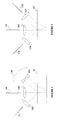
- Figure 1 is a schematic drawing of the preferred embodiment of thickness monitoring apparatus.
- Figure 2 is an expanded view of the surface of the film being measured.
- Figure 3 illustrates the output generated by an autocorrelation receiver when used with the apparatus of Figure 1.
- Figure 4 is a cross-sectional view of the fiber ends and lenses used in the apparatus of Figure 1.
- Figure 5 is a cross-sectional view of the fiber ends and lenses used in an alternate embodiment.
- Figure 6 is a schematic drawing of an embodiment utilizing an optical reflectometer for the receiver.
- FIG 1 is a schematic drawing of the preferred embodiment of thickness monitoring apparatus 10 which utilizes a low coherence light source 12 to generate a light signal that is split by a 3 dB coupler 16 into two parts that are applied to a film 15 whose thickness is to be measured.
- the light signals are applied via fibers 13 and 14.
- the first signal strikes film 15 at approximately normal incidence while the second signal strikes the film at an oblique angle.
- Light reflected from the surfaces of the film is collected by the optical fibers.
- a mirror 11 reflects the light from fiber 13 that is reflected by the film back into fiber 13.
- the collected light is combined by coupler 16 to provide an output light signal on fiber 17 which is sent to a receiver which is preferably an optical autocorrelator.
- the coherence length of light source 12 must be small compared to the thickness of the film being measured.
- Such light sources are common in the optical reflectometry arts, and hence, will not be discussed in detail here. For the purposes of the present discussion, it is sufficient to note that an edge emitting light emitting diode may be utilized for light source 12.
- An exemplary autocorrelator 18 constructed from a Michelson interferometer is shown at 18.
- the light incident on Michelson interferometer is split into two beams by beam splitter 19 that traverse different paths.
- the first path is determined by the position of fixed mirror 20 and the second by moveable mirror 21.
- the light is recombined by splitter 19 and directed to a photodiode 22 which measures the intensity of the light which varies with the position of mirror 21 due to the interference of the light.
- FIG. 2 is an expanded view of the surface of film 15 in the region in which the oblique beam strikes film 15.
- n the index of refraction of the film.
- the optical path delay, B, along path 25 relative to path 24 is given by where it is assumed that the group index and index of refraction are approximately equal. If this approximation is not satisfied, then n 2 in Eq. (1) must be replaced by ring where ng is the group index, and the n in the numerator of Eq.(1) must be replaced by n g .
- a and B can be determined from the output of the autocorrelator.
- Figure 3 illustrates the output of autocorrelator 18.
- the optical delay in one branch of the autocorrelator matches the delay between two reflections, a peak will appear in the output of the autocorrelator. This is a direct result of the low coherence length of light source 12.
- the output of the autocorrelator will have a peak 31 corresponding to the difference in the optical paths for the normally incident light that is reflected off of the front and back surfaces of the film.
- the fiber ends are placed at some distance from the file to provide room for flutter and tolerance for angular variations in the reflective surface of the film that is inherent when the film flutters during rapid motion.
- lenses and reflective surfaces are utilized.
- the manner in which this arrangement operates may be more easily understood with reference to Figure 4 which is a cross-sectional view of the fiber ends, lenses, and film under measurement.
- Light leaving fiber 13 is collimated with the aid of lens 103.
- Light leaving film 15 is focused back into fiber 13 by lens 104 and mirror 110.
- lens 102 directs light leaving fiber 14 onto the film, collects the light reflected back from the film, and couples the light leaving the film and focuses the collected light back into fiber 14.
- Fiber 13 is replaced by two fibers 131 and 132.
- Fiber 131 and lens 134 act as a light source providing a collimated beam directed at the film.
- Lens 133 and fiber 132 collect the light reflected from the film. The light from fiber 132 is combined with that from fiber 14 in a coupler prior to being received by the autocorrelator.
- the above described embodiments utilize a Michelson interferometer as the autocorrelator
- other forms of autocorrelator may be utilized.
- an optical spectrum analyzer which measures the optical power as a function of wavelength or optical frequency can be utilized.
- the Fourier transform of the frequency domain spectrum provides an output which is identical to that of an autocorrelator.
- the light from a low coherence source 12 is split into two signals by a first coupler 161.
- the signal on fiber 164 is split into two signals to form a probe pair comprising fibers 130 and 140 which applies these signals at two angles of incidence to film 15 and collects the light reflected back by film 15.
- the light collected is recombined with the second light signal generated by coupler 161 at coupler 161 after the second light signal has traversed a variable reference path comprising moving mirror 121.
- the signals combined at coupler 161 will undergo constructive interference when the delay in the reference path matches the transit time for the signals on the probe arm of the reflectomer.
- the intensity of the light leaving coupler 161 is measured by a photodetector 121.
- This type of receiver may be purchased commercially (Hewlett Packard HP8504 Precision Reflectomer). From the output of the photodiode as a function of the mirror position X, the film thickness and index of refraction may be determined as discussed above.
- any type of reflectometer having sufficient spatial resolution to distinguish the film reflections can be used in this configuration.
- This configuration is not preferred because the results are sensitive to variations in the lengths of the various fibers. Such variations may occur due to temperature fluctuations or mechanical stress. In contrast, the results obtained with an autocorrelating receiver are independent of such fluctuations.
Landscapes
- Physics & Mathematics (AREA)
- General Physics & Mathematics (AREA)
- Length Measuring Devices By Optical Means (AREA)
- Investigating Or Analysing Materials By Optical Means (AREA)
Applications Claiming Priority (2)
| Application Number | Priority Date | Filing Date | Title |
|---|---|---|---|
| US08/520,200 US5646734A (en) | 1995-08-28 | 1995-08-28 | Method and apparatus for independently measuring the thickness and index of refraction of films using low coherence reflectometry |
| US520200 | 2000-03-07 |
Publications (3)
| Publication Number | Publication Date |
|---|---|
| EP0760459A2 true EP0760459A2 (de) | 1997-03-05 |
| EP0760459A3 EP0760459A3 (de) | 1997-11-26 |
| EP0760459B1 EP0760459B1 (de) | 2001-11-28 |
Family
ID=24071586
Family Applications (1)
| Application Number | Title | Priority Date | Filing Date |
|---|---|---|---|
| EP96305652A Expired - Lifetime EP0760459B1 (de) | 1995-08-28 | 1996-07-31 | System zum Messen der Dicke und des Brechungsindexes eines Films |
Country Status (4)
| Country | Link |
|---|---|
| US (1) | US5646734A (de) |
| EP (1) | EP0760459B1 (de) |
| JP (1) | JP3691597B2 (de) |
| DE (1) | DE69617335T2 (de) |
Cited By (1)
| Publication number | Priority date | Publication date | Assignee | Title |
|---|---|---|---|---|
| WO1999027342A3 (en) * | 1997-11-20 | 1999-08-12 | Tropel Corp | Grazing incidence interferometry for measuring transparent plane-parallel plates |
Families Citing this family (14)
| Publication number | Priority date | Publication date | Assignee | Title |
|---|---|---|---|---|
| US5838448A (en) * | 1997-03-11 | 1998-11-17 | Nikon Corporation | CMP variable angle in situ sensor |
| NO307675B1 (no) * | 1997-04-18 | 2000-05-08 | Lasse Leirfall | Anvendelse av en mÕleanordning til indikering av en forurenset, tilsmusset eller brannfarlig tilstand |
| EP0947862A3 (de) | 1998-03-31 | 2004-03-17 | Ntt Advanced Technology Corporation | Verfahren und Vorrichtung zur Aufrechterhaltung eines optischen Signals mit niedrigem Polarizationsgrad in einem spezifischen Polarisationszustand |
| US6157037A (en) * | 1998-12-04 | 2000-12-05 | Photosense, Llc | Sensing device and method for measuring emission time delay during irradiation of targeted samples |
| US6184985B1 (en) | 1998-12-11 | 2001-02-06 | Filmetrics, Inc. | Spectrometer configured to provide simultaneous multiple intensity spectra from independent light sources |
| US6172756B1 (en) | 1998-12-11 | 2001-01-09 | Filmetrics, Inc. | Rapid and accurate end point detection in a noisy environment |
| US6204922B1 (en) | 1998-12-11 | 2001-03-20 | Filmetrics, Inc. | Rapid and accurate thin film measurement of individual layers in a multi-layered or patterned sample |
| US6252670B1 (en) | 1999-10-29 | 2001-06-26 | Taiwan Semiconductor Manufacturing Company | Method for accurately calibrating a constant-angle reflection-interference spectrometer (CARIS) for measuring photoresist thickness |
| KR20030016935A (ko) * | 2001-08-23 | 2003-03-03 | 광주과학기술원 | 광섬유 렌즈의 초점거리를 이용한 물질의 두께 측정장치및 그 방법 |
| US6806969B2 (en) * | 2001-10-19 | 2004-10-19 | Agilent Technologies, Inc. | Optical measurement for measuring a small space through a transparent surface |
| JP4051443B2 (ja) * | 2003-03-20 | 2008-02-27 | 独立行政法人産業技術総合研究所 | 光学材料の群屈折率精密計測方法及び装置 |
| US20090283699A1 (en) * | 2003-09-29 | 2009-11-19 | Baltz Nathan T | Frequency domain luminescence instrumentation |
| US9696138B2 (en) | 2011-08-01 | 2017-07-04 | University Of Florida Research Foundation, Inc. | Simultaneous refractive index and thickness measurements with a monochromatic low-coherence interferometer |
| CN103267743B (zh) * | 2013-04-08 | 2018-09-21 | 辽宁科旺光电科技有限公司 | 一种折射率测量装置及方法 |
Family Cites Families (6)
| Publication number | Priority date | Publication date | Assignee | Title |
|---|---|---|---|---|
| US3631526A (en) * | 1969-11-05 | 1971-12-28 | Brun Sensor Systems Inc | Apparatus and methods for eliminating interference effect errors in dual-beam infrared measurements |
| DE2448294A1 (de) * | 1974-10-10 | 1976-04-22 | Bbc Brown Boveri & Cie | Verfahren und vorrichtung zur bestimmung von schichtdicke und brechungsindex von duennen durchsichtigen schichten |
| DE2758149C2 (de) * | 1977-12-27 | 1979-10-04 | Ibm Deutschland Gmbh, 7000 Stuttgart | Interferometrisches Verfahren mit λ /4-Auflösung zur Abstands-, Dicken- und/oder Ebenheitsmessung |
| US4453828A (en) * | 1981-12-02 | 1984-06-12 | Advanced Semiconductor Products, Inc. | Apparatus and methods for measuring the optical thickness and index of refraction of thin, optical membranes |
| JPS6435306A (en) * | 1987-07-31 | 1989-02-06 | Ricoh Kk | Incidence angle determining method for refractive index and film thickness measurement |
| US5323229A (en) * | 1992-08-31 | 1994-06-21 | Science Applications International Corporation | Measurement system using optical coherence shifting interferometry |
-
1995
- 1995-08-28 US US08/520,200 patent/US5646734A/en not_active Expired - Fee Related
-
1996
- 1996-07-19 JP JP19018096A patent/JP3691597B2/ja not_active Expired - Fee Related
- 1996-07-31 EP EP96305652A patent/EP0760459B1/de not_active Expired - Lifetime
- 1996-07-31 DE DE69617335T patent/DE69617335T2/de not_active Expired - Fee Related
Cited By (1)
| Publication number | Priority date | Publication date | Assignee | Title |
|---|---|---|---|---|
| WO1999027342A3 (en) * | 1997-11-20 | 1999-08-12 | Tropel Corp | Grazing incidence interferometry for measuring transparent plane-parallel plates |
Also Published As
| Publication number | Publication date |
|---|---|
| US5646734A (en) | 1997-07-08 |
| EP0760459B1 (de) | 2001-11-28 |
| JP3691597B2 (ja) | 2005-09-07 |
| DE69617335D1 (de) | 2002-01-10 |
| EP0760459A3 (de) | 1997-11-26 |
| JPH0972723A (ja) | 1997-03-18 |
| DE69617335T2 (de) | 2002-05-08 |
Similar Documents
| Publication | Publication Date | Title |
|---|---|---|
| US5633712A (en) | Method and apparatus for determining the thickness and index of refraction of a film using low coherence reflectometry and a reference surfaces | |
| US5642196A (en) | Method and apparatus for measuring the thickness of a film using low coherence reflectometry | |
| EP0760459B1 (de) | System zum Messen der Dicke und des Brechungsindexes eines Films | |
| US4046477A (en) | Interferometric method and apparatus for sensing surface deformation of a workpiece subjected to acoustic energy | |
| US5473432A (en) | Apparatus for measuring the thickness of a moving film utilizing an adjustable numerical aperture lens | |
| US5610716A (en) | Method and apparatus for measuring film thickness utilizing the slope of the phase of the Fourier transform of an autocorrelator signal | |
| US5731876A (en) | Method and apparatus for on-line determination of the thickness of a multilayer film using a partially reflecting roller and low coherence reflectometry | |
| US5850287A (en) | Roller assembly having pre-aligned for on-line thickness measurements | |
| US5064280A (en) | Method of measuring the velocity and/or length of endless webs of textile material and apparatus for carrying out the method | |
| US6034774A (en) | Method for determining the retardation of a material using non-coherent light interferometery | |
| US3645623A (en) | Apparatus for monitoring film thickness by reflecting a light beam from the film surface | |
| US4121470A (en) | Opto-electric sensing means with predetermined directional characteristic for ultrasonic waves | |
| US4647205A (en) | Method and interferometer for the measurement of short distances | |
| US4485309A (en) | Apparatus for contact-free sensing of a moving coherent mass of material | |
| JP3223942B2 (ja) | 光ファイバ検査装置 | |
| JP2005106706A (ja) | 屈折率及び厚さの測定装置ならびに測定方法 | |
| KR100241028B1 (ko) | 레이저를 이용한 내부결함 검출방법 및 그 장치 | |
| CN223636808U (zh) | 薄膜厚度测量装置 | |
| JP3040140B2 (ja) | 色収差測定方法及び測定装置 | |
| JPH0470536A (ja) | レーザ損傷しきい値測定装置 | |
| JPH06281418A (ja) | 凹凸を有する板状透明体の光学的厚さ測定方法 | |
| JP3160103B2 (ja) | 光学式ガラス板厚測定方法 | |
| RU1768973C (ru) | Устройство измерени геометрических параметров поверхностей | |
| KR0129055B1 (ko) | 강판 표면의 평균표면거칠기 및 공간주파수 동시 측정방법 및 이를 실시하기 위한 광학 시스템 | |
| Holly | Lateral Interferometry-Its Characteristics, Technology and Applications |
Legal Events
| Date | Code | Title | Description |
|---|---|---|---|
| PUAI | Public reference made under article 153(3) epc to a published international application that has entered the european phase |
Free format text: ORIGINAL CODE: 0009012 |
|
| AK | Designated contracting states |
Kind code of ref document: A2 Designated state(s): DE FR GB |
|
| PUAL | Search report despatched |
Free format text: ORIGINAL CODE: 0009013 |
|
| AK | Designated contracting states |
Kind code of ref document: A3 Designated state(s): DE FR GB |
|
| 17P | Request for examination filed |
Effective date: 19980209 |
|
| 17Q | First examination report despatched |
Effective date: 19991221 |
|
| GRAG | Despatch of communication of intention to grant |
Free format text: ORIGINAL CODE: EPIDOS AGRA |
|
| RAP1 | Party data changed (applicant data changed or rights of an application transferred) |
Owner name: HEWLETT-PACKARD COMPANY, A DELAWARE CORPORATION |
|
| GRAG | Despatch of communication of intention to grant |
Free format text: ORIGINAL CODE: EPIDOS AGRA |
|
| GRAH | Despatch of communication of intention to grant a patent |
Free format text: ORIGINAL CODE: EPIDOS IGRA |
|
| GRAH | Despatch of communication of intention to grant a patent |
Free format text: ORIGINAL CODE: EPIDOS IGRA |
|
| RAP1 | Party data changed (applicant data changed or rights of an application transferred) |
Owner name: AGILENT TECHNOLOGIES INC. |
|
| RAP1 | Party data changed (applicant data changed or rights of an application transferred) |
Owner name: AGILENT TECHNOLOGIES INC. A DELAWARE CORPORATION |
|
| RAP1 | Party data changed (applicant data changed or rights of an application transferred) |
Owner name: AGILENT TECHNOLOGIES, INC. (A DELAWARE CORPORATION |
|
| GRAA | (expected) grant |
Free format text: ORIGINAL CODE: 0009210 |
|
| AK | Designated contracting states |
Kind code of ref document: B1 Designated state(s): DE FR GB |
|
| PG25 | Lapsed in a contracting state [announced via postgrant information from national office to epo] |
Ref country code: FR Free format text: LAPSE BECAUSE OF FAILURE TO SUBMIT A TRANSLATION OF THE DESCRIPTION OR TO PAY THE FEE WITHIN THE PRESCRIBED TIME-LIMIT Effective date: 20011128 |
|
| REG | Reference to a national code |
Ref country code: GB Ref legal event code: IF02 |
|
| REF | Corresponds to: |
Ref document number: 69617335 Country of ref document: DE Date of ref document: 20020110 |
|
| PGFP | Annual fee paid to national office [announced via postgrant information from national office to epo] |
Ref country code: FR Payment date: 20020702 Year of fee payment: 7 |
|
| EN | Fr: translation not filed | ||
| PLBE | No opposition filed within time limit |
Free format text: ORIGINAL CODE: 0009261 |
|
| STAA | Information on the status of an ep patent application or granted ep patent |
Free format text: STATUS: NO OPPOSITION FILED WITHIN TIME LIMIT |
|
| 26N | No opposition filed | ||
| PGFP | Annual fee paid to national office [announced via postgrant information from national office to epo] |
Ref country code: DE Payment date: 20070831 Year of fee payment: 12 |
|
| PGFP | Annual fee paid to national office [announced via postgrant information from national office to epo] |
Ref country code: GB Payment date: 20070727 Year of fee payment: 12 |
|
| GBPC | Gb: european patent ceased through non-payment of renewal fee |
Effective date: 20080731 |
|
| PG25 | Lapsed in a contracting state [announced via postgrant information from national office to epo] |
Ref country code: DE Free format text: LAPSE BECAUSE OF NON-PAYMENT OF DUE FEES Effective date: 20090203 |
|
| PG25 | Lapsed in a contracting state [announced via postgrant information from national office to epo] |
Ref country code: GB Free format text: LAPSE BECAUSE OF NON-PAYMENT OF DUE FEES Effective date: 20080731 |