EP0760456B1 - Rotary drum melting furnace - Google Patents
Rotary drum melting furnace Download PDFInfo
- Publication number
- EP0760456B1 EP0760456B1 EP96401717A EP96401717A EP0760456B1 EP 0760456 B1 EP0760456 B1 EP 0760456B1 EP 96401717 A EP96401717 A EP 96401717A EP 96401717 A EP96401717 A EP 96401717A EP 0760456 B1 EP0760456 B1 EP 0760456B1
- Authority
- EP
- European Patent Office
- Prior art keywords
- melting furnace
- flanges
- cooling circuit
- enclosure
- furnace according
- Prior art date
- Legal status (The legal status is an assumption and is not a legal conclusion. Google has not performed a legal analysis and makes no representation as to the accuracy of the status listed.)
- Expired - Lifetime
Links
Images


Classifications
-
- F—MECHANICAL ENGINEERING; LIGHTING; HEATING; WEAPONS; BLASTING
- F27—FURNACES; KILNS; OVENS; RETORTS
- F27B—FURNACES, KILNS, OVENS, OR RETORTS IN GENERAL; OPEN SINTERING OR LIKE APPARATUS
- F27B7/00—Rotary-drum furnaces, i.e. horizontal or slightly inclined
-
- F—MECHANICAL ENGINEERING; LIGHTING; HEATING; WEAPONS; BLASTING
- F27—FURNACES; KILNS; OVENS; RETORTS
- F27B—FURNACES, KILNS, OVENS, OR RETORTS IN GENERAL; OPEN SINTERING OR LIKE APPARATUS
- F27B7/00—Rotary-drum furnaces, i.e. horizontal or slightly inclined
- F27B7/20—Details, accessories, or equipment peculiar to rotary-drum furnaces
- F27B7/38—Arrangements of cooling devices
-
- F—MECHANICAL ENGINEERING; LIGHTING; HEATING; WEAPONS; BLASTING
- F27—FURNACES; KILNS; OVENS; RETORTS
- F27B—FURNACES, KILNS, OVENS, OR RETORTS IN GENERAL; OPEN SINTERING OR LIKE APPARATUS
- F27B7/00—Rotary-drum furnaces, i.e. horizontal or slightly inclined
- F27B7/20—Details, accessories, or equipment peculiar to rotary-drum furnaces
- F27B7/2083—Arrangements for the melting of metals or the treatment of molten metals
Landscapes
- Engineering & Computer Science (AREA)
- Mechanical Engineering (AREA)
- General Engineering & Computer Science (AREA)
- Furnace Details (AREA)
- Muffle Furnaces And Rotary Kilns (AREA)
- Gasification And Melting Of Waste (AREA)
Description
L'invention concerne un four de fusion
tournant suivant le préambule de la revendication 1,
qui est basé sur US-A-3 510 115.The invention relates to a melting furnace.
turning according to the preamble of
La fusion de produits réfractaires, tels que la zircone et la magnésie qui fondent à 2700°C et 2800°C respectivement, impose l'emploi de fours spéciaux tels que les fours tournants à arc électrique. Ces fours comprennent une enceinte cylindrique dont l'axe est occupé par des électrodes entre lesquelles l'arc est dardé, et cette enceinte est mise en rotation pour que la matière à fondre se rassemble sur la paroi de l'enceinte et la protège des échauffements excessifs, formant ce qu'on appelle un auto-creuset, car elle ne fond que pour la couche superficielle donnant sur le centre du four et reste à de plus basses températures vers les couches extérieures adjacentes à l'enceinte.The merger of refractory products, such as zirconia and magnesia which melt at 2700 ° C and 2800 ° C respectively, requires the use of ovens specials such as rotary arc furnaces. These ovens include a cylindrical enclosure of which the axis is occupied by electrodes between which the arc is darted, and this enclosure is rotated so that the material to be melted collects on the wall of the enclosure and protects it from overheating excessive, forming what is called a self-crucible, because it only melts for the surface layer overlooking the center of the oven and stays at lower temperatures to the outer layers adjacent to the enclosure.
Malgré cette protection offerte par une partie de la matière à fondre, l'enceinte doit être refroidie.Despite this protection offered by a part of the material to be melted, the enclosure must be cooled.
Elle est formée de trois parties dans un four connu : deux flasques d'extrémité en forme de disque et une virole cylindrique qui les unit. Les flasques sont fixes et seule la virole tourne, ce qui impose de rétablir la continuité de l'enceinte par des joints intercalaires. Les flasques sont boulonnés à une virole extérieure fixe qui entoure la virole tournante et la soutient par l'intermédiaire de roulements. L'intervalle entre les viroles forme une chambre affectée au refroidissement de la virole intérieure. On utilise pour cela un circuit d'aspersion à conduit d'alimentation débouchant au sommet de la chambre, où il se termine par des buses d'aspersion, et un conduit de collecte débouchant au bas de la chambre.It is made up of three parts in one known oven: two end flanges in the form of disc and a cylindrical ferrule which unites them. The flanges are fixed and only the ferrule turns, which imposes to restore the continuity of the enclosure by interlayer seals. The flanges are bolted to a fixed outer shell which surrounds the rotating shell and supports it through bearings. The interval between the ferrules forms a chamber assigned to the cooling of the inner shell. We uses a pipe sprinkler system for this outlet leading to the top of the chamber, where it ends with spray nozzles, and a conduit collection opening at the bottom of the room.
La chambre doit donc être isolée à ses bords longitudinaux par des joints d'étanchéité pour éviter les fuites et protéger les roulements.The room must therefore be isolated from longitudinal edges by seals for avoid leaks and protect the bearings.
Comme les flasques doivent aussi être refroidis et que des précautions doivent être prises pour éviter les transferts d'arc le long de l'enceinte il faut ajouter deux circuits de refroidissement et de multiples joints d'étanchéité et d'isolation électrique entre la virole intérieure et les flasques d'une part, et la virole extérieure et d'autres parties fixes de l'installation d'autre part. L'agencement du four devient alors très compliqué.As the flanges must also be cooled and precautions must be taken to avoid arc transfers along the enclosure two cooling circuits must be added and multiple seals and electrical insulation between the inner shell and the flanges on the one hand, and the outer shell and other fixed parts of the installation on the other hand. Furnace layout then becomes very complicated.
L'objet de l'invention est de simplifier les fours de fusion tournants, notamment en ce qui concerne les dispositifs liés à leur support à un bâti fixe, leur refroidissement et l'agencement de joints d'isolation électrique qui les séparent en plusieurs parties.The object of the invention is to simplify rotating melting furnaces, in particular with regard to concerns devices linked to their support to a frame fixed, their cooling and the arrangement of seals of electrical insulation which separate them into several parts.
Les inventeurs ont constaté que ces objets pouvaient être atteints en rendant la virole solidaire des flasques et en prévoyant un circuit de refroidissement unique pour les flasques et la virole, malgré les difficultés pour assurer un écoulement correct le long de cette enceinte de grande surface et de forme complexe qui impose des pertes de charges importantes.The inventors have found that these objects could be achieved by making the shell integral flanges and by providing a circuit unique cooling for flanges and ferrule, despite the difficulties in ensuring a flow okay along this large area enclosure and of complex shape which imposes pressure losses important.
Dans sa nouvelle conception, le four peut être soutenu à partir essentiellement du flasque par lequel pénètre l'arc, par un arbre creux livrant passage à une des électrodes, et le circuit de refroidissement peut se terminer au niveau de cet arbre : les dispositifs d'alimentation en liquide de refroidissement et d'étanchéité sont reportés à cet endroit hors de l'enceinte et le four est alors très simplifié.In its new design, the oven can be supported essentially from the flange by which enters the arc, by a hollow shaft delivering passage to one of the electrodes, and the circuit cooling can end at this tree: the liquid supply devices of cooling and sealing are carried over to this place outside the enclosure and the oven is then very simplified.
La circulation du liquide de refroidissement peut être facilitée en donnant au circuit une forme ou une orientation permettant, à la rotation du four, de propulser le liquide dans le sens de l'écoulement par les forces d'inertie. On peut ainsi promouvoir un écoulement spiral dans les flasques et un écoulement hélicoïdal le long de la virole.The circulation of the liquid cooling can be facilitated by giving the circuit a shape or orientation allowing, at the rotation of the furnace, to propel the liquid in the direction of flow by inertial forces. We can thus promote a spiral flow in the flanges and a helical flow along the shell.
Le circuit de refroidissement est avantageusement creusé dans les flasques et la virole et prend la forme d'un circuit à contre-courant, où le liquide circule dans le four en formant deux nappes ou deux couches superposées. En pratique, les flasques et la virole sont généralement produits séparément et assemblés, et il serait difficile de raccorder les portions du circuit de refroidissement de ces pièces sans ajouter des joints d'étanchéité qui seraient soumis à une température élevée et compliqueraient de nouveau l'agencement. C'est pourquoi il est probablement meilleur que les portions de circuit de refroidissement débouchent sur la face externe de l'enceinte, sans se raccorder entre elles, et soient réunies par des tuyaux contournant les raccordements de la virole aux flasques.The cooling circuit is advantageously dug in the flanges and the ferrule and takes the form of a counter-current circuit, where the liquid circulates in the oven forming two layers or two overlapping layers. In practice, the flanges and the ferrule are generally produced separately and assembled, and it would be difficult to connect the portions of the cooling system of these parts without adding gaskets which would subjected to high temperature and would complicate new layout. That's why it is probably better than the circuit portions of cooling lead to the external face of the enclosure, without connecting to each other, and are joined by pipes bypassing the connections of the ferrule with the flanges.
Ces caractéristiques de l'invention ainsi que d'autres seront décrites plus en détail à l'aide des figures suivantes, qui sont annexées à titre illustratif et non limitatif :
- la figure 1 est une vue d'une réalisation de l'invention,
- la figure 2 est une vue d'une autre réalisation,
- la figure 3 est un détail de la figure 1 pris selon la coupe III-III,
- et la figure 4 est un détail de la figure 1 pris selon la coupe IV-IV.
- FIG. 1 is a view of an embodiment of the invention,
- FIG. 2 is a view of another embodiment,
- FIG. 3 is a detail of FIG. 1 taken along section III-III,
- and Figure 4 is a detail of Figure 1 taken along section IV-IV.
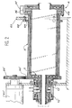
On aborde le commentaire de la figure 1.
L'essentiel de la structure du four est formé par une
enceinte 1 composée d'une virole cylindrique 2 unie à
un flasque de support 3 et à un flasque de coulée 4,
tous deux en forme de disque. Le flasque de support 3
est prolongé par un arbre 5 creux, coaxial à la virole
2 et qu'occupe une électrode 6 qui s'étend sur une
grande partie de la longueur de l'enceinte 1, selon son
axe, et darde l'arc électrique agent de la fusion vers
une autre électrode 46, qui traverse le flasque de
coulée 4 à l'emplacement d'un trou de coulée 56
central. L'arc est rayonné vers la matière à fondre,
qui couvre la face interne de la virole 2 en
fonctionnement, quand l'enceinte 1 tourne. La seconde
électrode 6 est retirée avant de déverser la matière
fondue hors de l'enceinte 1.We discuss the commentary on figure 1.
Most of the structure of the oven is formed by a
L'arbre 5 est soutenu par un bâti 7 par
l'intermédiaire d'un roulement 8. Il est entouré par
une boíte 9 de distribution et de collecte de liquide
de refroidissement, en forme de bague, traversée à son
sommet par un conduit d'alimentation 10 et par un
conduit de collecte 11. La boíte 9 est soutenue à ses
extrémités axiales par une paire de roulements 12 et 13
qui l'unissent à l'arbre creux 5. Deux paires de joints
14, 15 et 16, 17 s'étendant tous entre l'arbre 5 et le
boítier 9 -et encadrés par les roulements 12 et 13- ont
pour fonction d'isoler les conduits d'alimentation 10
et de collecte 11 l'un de l'autre et des roulements 12
et 13.The
L'enceinte 1 est formée de trois couches
pleines séparées par des canaux superposés formant le
circuit de refroidissement. On verra que ces canaux
forment en réalité un canal unique dans la totalité de
l'enceinte 1. Le flasque de support 3 est ainsi creusé
d'un canal d'alimentation 18 et d'un canal de collecte
19 conjoints, plans et circulaires, et qui se
prolongent par des portions annulaires et concentriques
dans l'arbre 5. Cependant, alors que le canal de
collecte 19 est parfaitement dégagé, le canal
d'alimentation 18 est en partie occupé, dans le flasque
3, par une spirale 20 (bien visible à la figure 4) qui
le transforme en canal spiral dans lequel un écoulement
centrifuge du liquide de refroidissement est assuré
grâce au sens de rotation de l'enceinte 1. Les canaux
d'alimentation 18 et de collecte 19 se terminent dans
l'arbre creux par des gorges ou des rigoles circulaires
58 et 59 adjacentes dans lesquelles les conduits
d'alimentation 10 et de collecte 11 débouchent
respectivement : quelle que soit la position de
l'enceinte 1, la circulation d'eau de refroidissement
est donc ininterrompue pendant la rotation. Cette
construction apparaít pleinement à la figure 3.
La virole 2 est elle-même creusée d'un
canal 21 d'alimentation et d'un canal de retour 22
concentriques et annulaires ; le canal de retour 22 est
entièrement dégagé mais le canal d'alimentation 21 est
occupé par une hélice 43 qui le transforme en canal
hélicoïdal dans lequel le liquide de refroidissement se
voit imposer un écoulement dirigé vers le flasque de
coulée 4 quand l'enceinte 1 tourne.The
Les canaux d'alimentation 21 et de retour
22 ne s'étendent pas jusqu'au bout de la virole 2 mais
se terminent par des orifices, 23 et 24 respectivement,
du côté du flasque du support 3, et 25 et 26
respectivement du côté du flasque de coulée 4. Tous ces
orifices 23 à 26 ont une direction radiale et forment
donc des coudes avec les canaux 21 et 22. Supply channels 21 and
Les orifices 23 et 24 débouchent donc sur
la face externe de l'enveloppe 1 à côté d'orifices 27
et 28 des canaux d'alimentation 18 et de collecte 19 du
flasque de support 3. On dispose alors des tuyaux en
arceau 29 et 30 pour relier respectivement les orifices
23 et 27 et les orifices 24 et 28. Grâce à cette
disposition, la virole 2 peut être assemblée au flasque
de support 3 par des boulons 31, sans précautions
particulières et notamment sans qu'il soit besoin de
prévoir des systèmes d'étanchéité compliqués.The
Le flasque de coulée 4 est lui-même muni
d'un canal d'alimentation 32 et d'un canal de retour 33
munis d'orifices 34 et 35 respectifs débouchant à sa
périphérie et à côté des orifices 25 et 26. Il suffit
alors d'ajouter d'autres tuyaux en arceau 36 et 37,
respectivement entre les orifices 25 et 34 et entre les
orifices 26 et 35, pour que le circuit de
refroidissement soit parfaitement unifié entre les
conduits d'alimentation 10 et de collecte 11, les
canaux d'alimentation et de retour 32 et 33 se
raccordant en une jonction 45 autour du trou de coulée
56.The casting flange 4 is itself provided
a
De façon analogue aux autres portions de
l'enceinte 1, le canal de retour 33, par ailleurs plan
et circulaire, est parfaitement dégagé, alors que le
canal d'alimentation 32, lui aussi plan, circulaire et
parallèle au précédent, est occupé par une spirale 44
qui impose un mouvement centripète au liquide de
refroidissement quand l'enceinte 1 tourne : son
orientation est donc opposée à celle de la spirale 20
du flasque de support 3.Similarly to the other portions of
Une bride 57 est liée à la virole 2, près
du flasque de coulée 4, par des boulons 47 ; elle porte
une couronne dentée 38 qui engrène avec un pignon 39
d'un moteur 40 fixé au bâti 7. Par ailleurs, un
roulement 41 est disposé entre la bride 57 et le bâti
7. Les roulements 8 et 41 soutiennent ainsi
parfaitement l'ensemble constitué par l'enceinte 1 et
l'arbre creux 5 qui le prolonge, par ses deux
extrémités. Le moteur 40 entraíne l'enceinte 1 en
rotation par l'intermédiaire de la couronne dentée 38
et de la bride 57.A
Les boulons 47 servent aussi à assembler le
flasque de coulée 4 à la virole 2 ; il s'agit de
boulons isolants, car on désire établir une barrière
aux écoulements d'électricité et aux amorces d'arc
entre ces deux pièces. On intercale pour cela une
garniture circulaire isolante 48, que les boulons 47
compriment, entre les faces en vis-à-vis de la virole 2
et du flasque de coulée 4 ; les tubes en arceau 36 et
37 sont aussi isolants, de même que l'eau de
refroidissement à un degré suffisant, car elle est
déminéralisée. Il a été constaté qu'aucun autre joint
isolant n'était nécessaire en pratique, ce qui diffère
grandement du four connu, même s'il faut ici aussi
prévoir des manchons isolants 49 et 50 dans l'arbre
creux 5 et le trou de coulée 56 pour isoler ces pièces
des électrodes 6 et 46, et des disques isolants 51 et
52 couvrant les faces internes des flasques 3 et 4 afin
qu'ils ne fixent pas l'arc.
La figure 2 illustre un agencement un peu
différent. Les électrodes 6 et 46 et les disques
isolants 51 et 52 ont été omis de la représentation
pour l'alléger.Figure 2 illustrates a somewhat
different. The
Le moteur 40 est déplacé et prend la
référence 40' ; il est situé près de l'arbre creux 5 et
son pignon 39' engrène avec une couronne dentée 38'
construite à la périphérie du flasque de support 3. De
plus, ce dernier est d'une pièce avec la virole 2, et
leurs canaux d'alimentation 18 et 21, de même que leurs
canaux de collecte 19 et de retour 22, communiquent
directement, sans orifice ni raccord visible à
l'extérieur. Le flasque de coulée 4 reste séparé de la
virole 2 par la garniture circulaire isolante 48, et on
retrouve donc les tuyaux en arceau 36 et 37 pour relier
leurs canaux.The
Le roulement 41 a disparu et est remplacé
par une série de galets 62 montés sur une couronne 63
qui s'élève du bâti 7 et entoure la virole 2 près du
flasque de coulée 4, vers l'emplacement où existait la
bride 57, elle aussi disparue. Une collerette 64
d'appui des galets 62 peut cependant être ajoutée sur
la virole 2.
La boíte 9 porte désormais l'arbre creux 5
et l'enceinte 1. Elle est alors vissée au bâti 7. Les
roulements 12 et 13 doivent maintenant soutenir un
poids plus important et sont avantageusement remplacés
par des roulements plus résistants tels que des
roulements à rouleaux 12' et 13'.The
On n'a évoqué qu'un chauffage électrique
par des électrodes coaxiales 6 et 46. D'autres modes de
chauffage sont compatibles avec l'invention : des
torches à gaz ou à plasma, des éléments chauffants par
effet Joule, des inducteurs ou des guides d'ondes.
L'arbre creux 5 peut être remplacé par un arbre plein
dans certaines de ces solutions, le dispositif
chauffant étant introduit par le trou de coulée 56.We only mentioned electric heating
by
Le bâti 7 est construit pour basculer à la
coulée et abaisser le trou de coulée 56.The
Claims (10)
- Rotary melting furnace comprising an enclosure (1) formed by a cylindrical shell (2) between two flanges (3, 4) and a cooling circuit for the enclosure, characterized in that the shell is connected to the flanges and that there is a single cooling circuit (18, 19, 21, 22, 32, 33, 29, 30, 36, 37) and has a part in the shell connected to a part in each of the flanges.
- Melting furnace according to claim 1, characterized in that the cooling circuit is essentially hollowed from the enclosure.
- Melting furnace according to claim 2, characterized in that each of the parts of the cooling circuit comprises two layers, where a countercurrent flow occurs.
- Melting furnace according to claim 1, characterized in that the cooling circuit is intended to bring about a cooling fluid flow when the furnace rotates.
- Melting furnace according to claim 4, characterized in that the part of the cooling circuit in the shell is at least partly in the form of a helical channel (21).
- Melting furnace according to claim 4, characterized in that the parts of the cooling circuit in the flanges are at least partly in the form of a spiral channel (18, 32).
- Melting furnace according to claim 1, characterized in that the parts of the cooling circuit are joined by pipes (29, 30, 36, 37) passing round the perimeters for joining the shell to the flanges.
- Melting furnace according to claim 1, characterized in that it comprises a shaft (5) for rotating and supporting the furnace fixed to one of the flanges (3).
- Melting furnace according to claim 8, characterized in that the rotation shaft is supported by bearings (8, 12', 13').
- Melting furnace according to claim 8, characterized in that the cooling circuit extends in the shaft (5), where it terminates in at least one circular groove (58, 59) on which opens a respective, fixed duct (10, 11) perpendicular to the shaft.
Applications Claiming Priority (2)
| Application Number | Priority Date | Filing Date | Title |
|---|---|---|---|
| FR9509462A FR2737554B1 (en) | 1995-08-03 | 1995-08-03 | ROTATING FUSION OVEN |
| FR9509462 | 1995-08-03 |
Publications (2)
| Publication Number | Publication Date |
|---|---|
| EP0760456A1 EP0760456A1 (en) | 1997-03-05 |
| EP0760456B1 true EP0760456B1 (en) | 2000-06-28 |
Family
ID=9481685
Family Applications (1)
| Application Number | Title | Priority Date | Filing Date |
|---|---|---|---|
| EP96401717A Expired - Lifetime EP0760456B1 (en) | 1995-08-03 | 1996-08-01 | Rotary drum melting furnace |
Country Status (7)
| Country | Link |
|---|---|
| US (1) | US5711664A (en) |
| EP (1) | EP0760456B1 (en) |
| JP (1) | JPH09119778A (en) |
| KR (1) | KR100436176B1 (en) |
| CA (1) | CA2181533A1 (en) |
| DE (1) | DE69609022T2 (en) |
| FR (1) | FR2737554B1 (en) |
Families Citing this family (8)
| Publication number | Priority date | Publication date | Assignee | Title |
|---|---|---|---|---|
| US6105272A (en) * | 1998-06-22 | 2000-08-22 | Cabot Corporation | High temperature rotating vacuum kiln for heat treating solid particulate material under a vacuum |
| US6042370A (en) * | 1999-08-20 | 2000-03-28 | Haper International Corp. | Graphite rotary tube furnace |
| KR100619481B1 (en) * | 2004-08-02 | 2006-09-08 | 이우범 | Codirectional rotary kiln with a rectangle bar |
| CN101936652A (en) * | 2010-09-05 | 2011-01-05 | 江苏金能环境科技有限公司 | Heat side kilneye protective cover for rotary kiln |
| US9550694B2 (en) | 2014-03-31 | 2017-01-24 | Corning Incorporated | Methods and apparatus for material processing using plasma thermal source |
| US9533909B2 (en) | 2014-03-31 | 2017-01-03 | Corning Incorporated | Methods and apparatus for material processing using atmospheric thermal plasma reactor |
| US9284210B2 (en) | 2014-03-31 | 2016-03-15 | Corning Incorporated | Methods and apparatus for material processing using dual source cyclonic plasma reactor |
| US20160200618A1 (en) | 2015-01-08 | 2016-07-14 | Corning Incorporated | Method and apparatus for adding thermal energy to a glass melt |
Family Cites Families (18)
| Publication number | Priority date | Publication date | Assignee | Title |
|---|---|---|---|---|
| FR527701A (en) * | 1920-11-26 | 1921-10-29 | Andre Simon Cerf | Rotary furnace for melting metals and alloys such as bronze, brass, tin and others |
| US2702743A (en) * | 1948-08-12 | 1955-02-22 | Koppers Co Inc | Method and apparatus for preheating gaseous and vaporous reagents in powdered fuel gasification |
| FR1526999A (en) * | 1967-02-20 | 1968-05-31 | Commissariat Energie Atomique | Rotary melting furnace |
| CH512045A (en) * | 1970-02-04 | 1971-08-31 | Holderbank Man & Beratung Ag | Cooling device for the outlet of a rotary drum furnace |
| US3751220A (en) * | 1972-11-24 | 1973-08-07 | Allis Chalmers | Fluid delivery system for rotary kiln |
| FR2398261A1 (en) * | 1977-07-20 | 1979-02-16 | Oconnor Chadwell | Rotating fluidized bed combustor - has sand rotated in horizontal cylindrical drum with steam blown through heated falling sand |
| US4185984A (en) * | 1978-02-06 | 1980-01-29 | Union Carbide Corporation | Process for producing glass in a rotary furnace |
| DE3039212A1 (en) * | 1980-10-17 | 1982-05-19 | Metallgesellschaft Ag, 6000 Frankfurt | METHOD FOR THE THERMAL TREATMENT OF PROTECTIVE GOODS IN THE TURNTUBE |
| US4443186A (en) * | 1982-04-14 | 1984-04-17 | The United States Of America As Represented By The United States Department Of Energy | Solar heated rotary kiln |
| US4785746A (en) * | 1985-04-25 | 1988-11-22 | Trw Inc. | Carbonaceous slurry combustor |
| DE3534991A1 (en) * | 1985-10-01 | 1987-04-02 | Gutehoffnungshuette Man | TURN TUBE COOLER |
| US4836775A (en) * | 1985-12-23 | 1989-06-06 | Ppg Industries, Inc. | Air cooled rotary kiln collar |
| KR900002421Y1 (en) * | 1987-04-28 | 1990-03-26 | 일양안티몬주식회사 | Smelting apparatus for antimony |
| US4948365A (en) * | 1989-05-24 | 1990-08-14 | Zond Systems, Inc. | High-temperature, gas-burning furnace |
| US5000680A (en) * | 1990-02-15 | 1991-03-19 | Boliden Allis, Inc. | Rotary kiln |
| WO1993002654A2 (en) * | 1991-08-09 | 1993-02-18 | New England Deaconess Hospital | A method of inducing hemoglobin synthesis in red blood cells and uses therefor |
| DE4419543C1 (en) * | 1994-06-03 | 1996-02-08 | Noell Gmbh | Rotary tube with cover cooling for combustion installations |
| US5515794A (en) * | 1995-01-23 | 1996-05-14 | Texaco Inc. | Partial oxidation process burner with recessed tip and gas blasting |
-
1995
- 1995-08-03 FR FR9509462A patent/FR2737554B1/en not_active Expired - Fee Related
-
1996
- 1996-07-18 CA CA002181533A patent/CA2181533A1/en not_active Abandoned
- 1996-07-22 US US08/681,062 patent/US5711664A/en not_active Expired - Fee Related
- 1996-07-30 KR KR1019960031513A patent/KR100436176B1/en not_active IP Right Cessation
- 1996-08-01 DE DE69609022T patent/DE69609022T2/en not_active Expired - Fee Related
- 1996-08-01 EP EP96401717A patent/EP0760456B1/en not_active Expired - Lifetime
- 1996-08-05 JP JP8206015A patent/JPH09119778A/en active Pending
Also Published As
| Publication number | Publication date |
|---|---|
| US5711664A (en) | 1998-01-27 |
| JPH09119778A (en) | 1997-05-06 |
| FR2737554A1 (en) | 1997-02-07 |
| KR970011766A (en) | 1997-03-27 |
| KR100436176B1 (en) | 2004-11-06 |
| DE69609022D1 (en) | 2000-08-03 |
| FR2737554B1 (en) | 1997-08-29 |
| DE69609022T2 (en) | 2001-02-22 |
| EP0760456A1 (en) | 1997-03-05 |
| CA2181533A1 (en) | 1997-02-04 |
Similar Documents
| Publication | Publication Date | Title |
|---|---|---|
| EP0760456B1 (en) | Rotary drum melting furnace | |
| EP0780546B1 (en) | Centrifugal separator for lubrication chamber | |
| CA2235051C (en) | Reel core for reeling a product in strip form and its utilization | |
| CA2635632C (en) | Dual turbofan | |
| EP0187563B1 (en) | Snow gun feeding devices in systems for providing ski slopes with artificial snow | |
| EP1999019A1 (en) | System for deicing an air inlet cowl for a turbine engine | |
| EP0892152A1 (en) | Heating or cooling device for a carter with circular section | |
| FR2481761A1 (en) | THERMAL BARRIER FOR CENTRIFUGAL PUMPS WITH HIGH TEMPERATURE AND WITHOUT PRESSE-ETOUPE | |
| BE621060A (en) | ||
| CH627834A5 (en) | COOLED WALL OF AN ARC FURNACE. | |
| EP1399597B1 (en) | Device for loading a shaft furnace | |
| CA2070506A1 (en) | Cooling device for the distribution chute of a shaft kiln charging installation | |
| US4385715A (en) | Rotary sliding closure unit and liquid melt container employing the same | |
| FR2543654A1 (en) | METHOD AND APPARATUS FOR LUBRICATING A GEAR TRANSMISSION | |
| EP0178981B1 (en) | Electrode structure for a molten metal bath | |
| FR2761119A1 (en) | Stator for axial=flow compressor, e.g. for aircraft | |
| WO2004037456A1 (en) | Cooled mandrel for winding a strip product | |
| FR2516597A1 (en) | ANNULAR AIR-COOLED WEAR AND SEAL DEVICE FOR GAS TURBINE WHEEL WELDING OR COMPRESSOR | |
| EP3502504B1 (en) | Torque transmission module intended for being provided on a transmission of a motor vehicle | |
| US3199158A (en) | Centrifugal furnace for fusion and casting under vacuum | |
| EP0484720B1 (en) | Device for injecting preheated air into a shaft furnace and a process for producing convex parts of ball-and-socket joints for tuyere connections | |
| EP0095428B1 (en) | Cooling device using gas for the vessel cover of a nuclear reactor | |
| FR2488380A1 (en) | PROCESS FOR MIXING THE HOT GASES OF AN OVEN WITH ANOTHER GAS BEFORE THE EXCHANGE OF THESE GASES, AND HOOD FOR CARRYING OUT SAID METHOD | |
| FR2787563A1 (en) | Tubular heat exchanger assembly, comprises concentrically mounted tubes mutually terminated at a recessed flange assembly | |
| FR2782552A1 (en) | Hydraulic feed assembly for closed circuit carrying liquid coolant e.g. for heating or cooling system has insulated housing for main components |
Legal Events
| Date | Code | Title | Description |
|---|---|---|---|
| PUAI | Public reference made under article 153(3) epc to a published international application that has entered the european phase |
Free format text: ORIGINAL CODE: 0009012 |
|
| AK | Designated contracting states |
Kind code of ref document: A1 Designated state(s): BE CH DE GB IT LI |
|
| 17P | Request for examination filed |
Effective date: 19970808 |
|
| GRAG | Despatch of communication of intention to grant |
Free format text: ORIGINAL CODE: EPIDOS AGRA |
|
| 17Q | First examination report despatched |
Effective date: 19990908 |
|
| GRAG | Despatch of communication of intention to grant |
Free format text: ORIGINAL CODE: EPIDOS AGRA |
|
| GRAH | Despatch of communication of intention to grant a patent |
Free format text: ORIGINAL CODE: EPIDOS IGRA |
|
| GRAH | Despatch of communication of intention to grant a patent |
Free format text: ORIGINAL CODE: EPIDOS IGRA |
|
| GRAA | (expected) grant |
Free format text: ORIGINAL CODE: 0009210 |
|
| AK | Designated contracting states |
Kind code of ref document: B1 Designated state(s): BE CH DE GB IT LI |
|
| REG | Reference to a national code |
Ref country code: CH Ref legal event code: EP |
|
| REF | Corresponds to: |
Ref document number: 69609022 Country of ref document: DE Date of ref document: 20000803 |
|
| ITF | It: translation for a ep patent filed |
Owner name: JACOBACCI & PERANI S.P.A. |
|
| GBT | Gb: translation of ep patent filed (gb section 77(6)(a)/1977) |
Effective date: 20000905 |
|
| PLBE | No opposition filed within time limit |
Free format text: ORIGINAL CODE: 0009261 |
|
| STAA | Information on the status of an ep patent application or granted ep patent |
Free format text: STATUS: NO OPPOSITION FILED WITHIN TIME LIMIT |
|
| 26N | No opposition filed | ||
| REG | Reference to a national code |
Ref country code: GB Ref legal event code: IF02 |
|
| PGFP | Annual fee paid to national office [announced via postgrant information from national office to epo] |
Ref country code: DE Payment date: 20070824 Year of fee payment: 12 |
|
| PGFP | Annual fee paid to national office [announced via postgrant information from national office to epo] |
Ref country code: CH Payment date: 20070823 Year of fee payment: 12 |
|
| PGFP | Annual fee paid to national office [announced via postgrant information from national office to epo] |
Ref country code: GB Payment date: 20070801 Year of fee payment: 12 |
|
| PGFP | Annual fee paid to national office [announced via postgrant information from national office to epo] |
Ref country code: IT Payment date: 20070828 Year of fee payment: 12 |
|
| PGFP | Annual fee paid to national office [announced via postgrant information from national office to epo] |
Ref country code: BE Payment date: 20071018 Year of fee payment: 12 |
|
| REG | Reference to a national code |
Ref country code: CH Ref legal event code: PL |
|
| GBPC | Gb: european patent ceased through non-payment of renewal fee |
Effective date: 20080801 |
|
| PG25 | Lapsed in a contracting state [announced via postgrant information from national office to epo] |
Ref country code: LI Free format text: LAPSE BECAUSE OF NON-PAYMENT OF DUE FEES Effective date: 20080831 Ref country code: CH Free format text: LAPSE BECAUSE OF NON-PAYMENT OF DUE FEES Effective date: 20080831 |
|
| PG25 | Lapsed in a contracting state [announced via postgrant information from national office to epo] |
Ref country code: BE Free format text: LAPSE BECAUSE OF NON-PAYMENT OF DUE FEES Effective date: 20080831 |
|
| PG25 | Lapsed in a contracting state [announced via postgrant information from national office to epo] |
Ref country code: IT Free format text: LAPSE BECAUSE OF NON-PAYMENT OF DUE FEES Effective date: 20080801 Ref country code: DE Free format text: LAPSE BECAUSE OF NON-PAYMENT OF DUE FEES Effective date: 20090303 |
|
| PG25 | Lapsed in a contracting state [announced via postgrant information from national office to epo] |
Ref country code: GB Free format text: LAPSE BECAUSE OF NON-PAYMENT OF DUE FEES Effective date: 20080801 |