EP0484720B1 - Device for injecting preheated air into a shaft furnace and a process for producing convex parts of ball-and-socket joints for tuyere connections - Google Patents
Device for injecting preheated air into a shaft furnace and a process for producing convex parts of ball-and-socket joints for tuyere connections Download PDFInfo
- Publication number
- EP0484720B1 EP0484720B1 EP91117866A EP91117866A EP0484720B1 EP 0484720 B1 EP0484720 B1 EP 0484720B1 EP 91117866 A EP91117866 A EP 91117866A EP 91117866 A EP91117866 A EP 91117866A EP 0484720 B1 EP0484720 B1 EP 0484720B1
- Authority
- EP
- European Patent Office
- Prior art keywords
- ball
- refractory
- pipe
- joint
- shielding
- Prior art date
- Legal status (The legal status is an assumption and is not a legal conclusion. Google has not performed a legal analysis and makes no representation as to the accuracy of the status listed.)
- Expired - Lifetime
Links
Images


Classifications
-
- C—CHEMISTRY; METALLURGY
- C21—METALLURGY OF IRON
- C21B—MANUFACTURE OF IRON OR STEEL
- C21B7/00—Blast furnaces
- C21B7/16—Tuyéres
- C21B7/163—Blowpipe assembly
Definitions
- the present invention relates to a device for injecting preheated air into a shaft furnace, consisting of several distinct cylindrical elements or segments consisting of an outer steel shield and an inner refractory lining and comprising at least one connected central tubular element, on one side, by a first spherical articulation and first compensator to an upper tube secured to a circular duct for supplying preheated air surrounding the furnace and, on the opposite side, by a second spherical articulation and a second compensator to a tube lower which is extended by an elbow and a nozzle, the latter being articulated on a nozzle fixed in the wall of the furnace and in which device the spherical joints comprise a convex ball formed by the end of one of the segments and able to pivot in a concave base formed by the end of the adjacent segment and a refracting joint soft interposed area.
- wind carrier is exposed to mobility and sealing problems. Indeed, due to the high temperature of the preheated air (temperature of the order of 1200 ° C. or more) and the high temperature prevailing inside the oven, the wall of the latter, as well as the pipe circular and the blower are exposed to thermal expansion and deformation causing significant relative displacements between the circular pipe and the wall of the oven. It is therefore necessary that the wind carrier is able to compensate for these relative displacements while avoiding leaks of gas or preheated air.
- US Patent No. 3,766,868 provides a wind carrier of the kind described in the preamble.
- This wind carrier was subsequently perfected by the design of a universal joint with a spherical joint of the kind described in document DE-C2-2218331.
- the three articulations of this wind carrier allow the compensation of all the relative movements between the circular duct and the wall of the furnace.
- the tightness at the joints is ensured by bellows compensators, while the mechanical stability is ensured by associated cardanic connections, at the two universal joints, at the two opposite ends of the central tubular element.
- the object of the present invention is to provide a new device of the kind described in the preamble, which has better resistance to wear at the joints, which, by its numerous variants, adapts perfectly to the requirements of the user. , which offers more ease of manufacture and replacement, while allowing a reasonable manufacturing price.
- the device proposed by the present invention is essentially characterized in that the radius of curvature of each spherical joint is of the order of magnitude of half the diameter of the various cylindrical elements and in that the convex ball joints of the spherical joints include a protective sheath made of refractory steel and which extends to the diametrical base of the ball joint.
- the reduction in the radius of curvature of the spherical joints allows better guidance of the ball joints in their base while reducing the risk of impact and wear of the soft joints and allowing to always keep the same width of the joint.
- the present invention also proposes a new method of manufacturing a convex ball joint of a spherical joint of a device for injecting preheated air into a shaft furnace, consisting in first making the ball joint sheath in refractory steel and providing this of an interior refractory lining, characterized in that the end of a refractory steel tube is deformed until it has the shape of a convex dome with a central opening and a surface convex spherical extending between the central opening and the cylindrical surface of the tube in that the sheath thus formed is placed on a support, in that there is axially inside a cylinder with a slightly diameter smaller than the diameter of said central opening and in that refractory material is poured between the cylinder and said sheath
- the ball joints are formed by the lower ends of the upper tube and of the central tubular element.
- the ball of the central tubular element can either form an integral part of this element, or be separated from it by a transverse cut filled by an annular seal.
- the shield of the central tubular element and that of the lower tubing can be connected directly to each other through a compensator, or by means of a flange or a detachable weld.
- the base of the lower joint can be formed in the refractory lining cast in a cylindrical sheath of refractory steel arranged coaxially inside the shielding of the lower pipe.
- the refractory soft seal can be partially attached to the shield and partially to the edge of the plate. It can also be partially attached in an interior housing of the cylindrical sheath and partially on the refractory. According to a variant, it can also be partially attached to the refractory and partially in a housing delimited by the upper part of the sheath and by a ring welded inside the shielding.
- the plates of the two spherical joints are provided respectively at the two opposite ends of the central tubular element, while the convex ball joints are provided on the upper tube and the lower tube.
- the known blower portrayed in FIG. 1 by the reference 20 connects a main circular pipe 22, arranged around a blast furnace, to the wall 24 thereof.
- This blower has a rectilinear oblique section consisting of a central tubular element 26 articulated at its upper end on a tube 28 fixed on a connector of the circular pipe 22 and, by its lower end on a tube 30 which is clamped on a elbow 32.
- This elbow 32 is extended by a nozzle 34 whose end is articulated on a nozzle 36 fixed in the wall 24 of the oven.
- the upper 38 and lower 40 joints between the central tubular element 26 and the two pipes 28 and 30 are universal joints allowing relative movements between the circular pipe 22 and the wall of the furnace 24.
- Each of the two joints 38, 40 is constituted by a convex part subsequently called a ball joint and by a concave part subsequently called a plate.
- the ball joint forms part of the upper tubing 28 and enters the plate formed by the upper end of the central element 26.
- the lower part of this forms the ball joint of the joint 40 and enters the plate formed by the upper part of the lower tube 40.
- the ball joint of the joint 40 is an integral part of the central element 26, that is to say that its refractory lining extends, without interruption, from the upper end to the tip of the patella.
- This constitution of the central element 26 facilitates its manufacture in comparison with the variant illustrated in FIG. 1a in which the ball joint is separated from the rest of the central element and is attached to the latter at the level of the flange provided for fixing. gimbal 50a.
- This variant illustrated in FIG. 1a has, on the other hand, the advantage of allowing separate disassembly of the lower part constituted by the tube 30 and the joint 40a or the upper part constituted by the rest of the central element 26 and l 'upper articulation 38 with the tubing 28.
- the upper articulation 38 must necessarily be constituted in accordance with FIG. 1a in order to be able to detach the wind carrier from the circular pipe 22.
- FIG. 2 illustrates a known embodiment of an articulation as proposed in document DE-C2-2218331.
- This embodiment is essentially distinguished from that of FIG. 1 by the fact that the articulations are spherical as shown by the joint between the ball joint 58 and the base of the tube 30.
- the ball joint 58 is also separated from the central element 26 like FIG. 1a.
- the embodiment according to Figure 1 remains however also possible.
- a first sealing ring 62 for example, made of ceramic fibers is incorporated into the refractory of the plate 60 and closes the passage between the plate 60 and the tip of the ball joint 58.
- Another seal also made of ceramic fibers is disposed in the annular space between the lower end of the metal sheath 68 of the ball joint 58 and the cylindrical connection of the compensator 44. This seal 64 is wedged between the edge of the plate 60 and a peripheral ring 66 welded to the sheath 68.
- seals 62 and 64 are essentially to prevent or reduce the penetration of hot air inside the compensators 44 in order to better protect them from high temperatures.
- the lower edge of the sheath 68 can come to crush the seal 64 on one side, while on the opposite side, the ring 66 tends to compress the seal 64 in the axial direction. Since these refractory joints lack elasticity, they risk undergoing by these movements an irreversible deformation, which reduces their effectiveness.
- This device according to FIG. 2 has another handicap, insofar as the sheath 68 of refractory steel extends only up to the limit of the cylindrical part of the ball joint 58.
- the refractory point of the ball joint 58 is, of this fact, quickly invaded by micro-cracks which are at the origin of a rapid wear and a rupture of the point of the patella.
- the absence of support for the refractory of the tip of the ball joint 58 also requires a relatively large radius of curvature R to prevent this convex tip not supported by the sheath 68 from being too tapered. This, in turn, is at the origin of the cutting edge between the cylindrical part and the convex part of the sheath 58 and which risks crushing the seal 64 during the angular movements of the ball joint.
- FIGS. 3 and 3a each show half of a joint in accordance with the present invention, the figures being brought together so as to show an entire joint, the left part of which represents the version with ball joint separated from the central segment and whose Right version is the one whose kneecap is part of the central segment.
- Figures 3 and 3a show that the ball proposed by the present invention 70, 70a is completely enveloped by its refractory steel sheath 72, 72a which extends to the base of the ball around its convex section.
- the manufacture of such a refractory sheath 72, 72a in one piece with a convex section is made possible by a clever manufacturing process explained in more detail below.
- the ball joint proposed by the present invention has a smaller radius of curvature, of the order of magnitude of half the diameter of the segments of the wind carrier, which improves its mobility.
- a joint 74 for example made of ceramic fibers, is provided between the ball joint 70, 70a and the refractory of the tubing 76.
- This joint can, for example, be bonded to the shielding of the tubing 76 between two retaining rings 78, 80
- the joint 74 perfectly matches the shape of the point of the ball joint and extends over the major part of the convex section thereof. If the wind carrier is designed to accommodate a maximum axial misalignment of 7 °, the ball joint 72, 71, can deviate by 3.5 ° on either side from its neutral position in the figures, which is illustrated in the angles ⁇ and ⁇ . During such extreme pivoting, the seal 74 always forms a thick sealing cushion without being compressed by the ball joint 70, 71, owing to the fact that the width of the slot remains constant during the relative pivotings.
- a cylindrical tube 82 made of refractory steel is used, possibly provided with a small peripheral flange 84 if it is the embodiment of FIG. 3.
- a small peripheral flange 84 On the side opposite to the flange 84, it is practiced on all around, at regular intervals, cuts according the generator, of a depth corresponding to the length of the convex section of the patella to be produced.
- These cutouts 86 thus define tongues 88 identical to each other.
- tongues 88 are then folded down towards the axis of the tube 82 until the cutouts 86 are completely closed to define a spherical dome having a central opening 90 formed by the front facets 92 juxtaposed with the tongues 88.
- This folding of the tongues 88 can be carried out in a mold with a spherical bottom.
- the sheath 72 is then finished by welding the different tabs 88 to one another over the entire length of the cuts.
- FIG. 5 illustrates a first embodiment of the oblique section of a wind carrier with two spherical articulations 94 and 96 identical to each other and each comprising a ball joint wrapped in a refractory steel sheath produced according to the method described with reference to FIG. 4.
- the means for mechanical stabilization of the joints 94 and 96 have not been shown.
- These means although present in practice, may be means known per se, such as cardan joints or tie rods in accordance with document EP-A1-0363576.
- FIG. 5a illustrates the variant already described above, according to which the ball joint of the lower articulation 96a is separated from the central tubular element 98a.
- the sealed connection between the central element 98 and the lower tube 100 is produced by means of a flange 102 at the upper end of the sheath of the ball joint.
- the central element 98 also includes an upper flange 104 beyond the compensator of the upper articulation 94 to be fixed to the connector of the circular pipe not shown.
- these flanges 102 and 104 are moreover necessary in order to be able to manufacture the three elements separately, namely the central element 98, the lower tube 100 and the upper tube 106 which is simply constituted by the ball joint of the ball joint 94. This fabrication will now be illustrated with reference to FIGS. 6a, 6b and 6c.
- FIG. 6a illustrates the manufacture of the refractory of the ball joint 106.
- the sheath 72 produced according to the method described with reference to FIG. 4 is turned over on a support 108, for example made of wood, the central opening 90, of preferably down.
- a cylindrical shape 110 for example made of expanded synthetic material, is introduced into the sheath 72 and it is ensured that it is held in place, for example by means of a plug 112 fixed in the support 108 and penetrating into an axial channel of the form 110. It therefore only remains to pour the refractory material 114 into the annular space delimited by the form 110 and the sheath 72 by using the latter as a mold.
- FIG. 6b illustrates the manufacture of the central element 98.
- the assembly formed by the shield 116 of the central element with the sheath of the lower ball joint and the upper compensator is turned over, the flange 104 downwards.
- the ring 120 delimiting the housing of the joint of the upper articulation 94 closing the opening around the support.
- the upper profile of the support 118 is complementary to the shape of the base of the articulation 94.
- Figure 6c illustrates the manufacture of the lower tubing.
- the shield 126 of this tube including the compensator of the lower joint is turned upside down, upper flange, on a support 128 identical to the support 118 used previously.
- a form of expanded synthetic material 130 whose external shape corresponds to the inner channel of the tubing 100 finished and the space around the shape 130 is filled with refractory material.
- the three forms of synthetic material 110, 122 and 130 can remain in place for the purpose of mounting the blower, since they will be consumed automatically when the blower is put into service.
- FIG. 7 shows a second embodiment of a wind carrier with a central element 132, a lower tube 134 and a ball joint 136.
- the shielding of the central element 132 is connected through the compensator of the lower articulation to the shielding of the pipe 134.
- the flange 102 of the embodiment of FIG. 5 has therefore disappeared, which makes it possible to reduce the manufacturing price of the wind carrier .
- the manufacturing step illustrated in Figure 6c is no longer possible and it is necessary to provide other devices in order to be able to pour the plate of the lower joint.
- the refractory of the tubing 134 is poured in two successive operations, which is symbolized by the interruption 138.
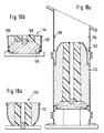
- This also has repercussions on the design of the lower articulation, in particular of the 'trim of the tubing 134 and Figures 8 and 9 illustrate several embodiments.
- FIG. 8 shows the details of the spherical joint 140 between the central element 132 and the lower tube 134.
- the ball joint 142 is identical to the previous embodiment, that is to say with a refractory sheath produced according to the figure 4.
- the base 144 of the joint 140 formed by the upper part of the refractory lining of the tubing 134 is modified.
- the refractory lining forming the plate 144 is poured inside a cylindrical sheath 146 made of refractory steel and arranged coaxially inside the metal shielding of the pipe 134.
- the sheath 146 can be held in place by means of two rings 148 and 150 fixed respectively on the inner wall of the shield and the outer wall of the sleeve 146.
- the thermal insulation is ensured by a thick seal 152 made of ceramic fibers bonded to the inner surface of the shielding of the tubing 134 and extending downward between the ball joint 142 and the plate 144.
- Two annular supports 154 and 156 welded to the shielding maintain this seal.
- the plate 144 is also placed inside a sheath 158 of refractory steel which, compared to the embodiments of FIG. 8, is longer than the sheath 146.
- the part of the sheath 158 which exceeds the refractory lining is in fact designed as a housing for the seal 160 made of ceramic fibers.
- the embodiment of FIG. 9 has, compared to that of FIG. 8, the advantage that the seal 160 can be put in place before the assembly of the wind carrier and be introduced with the plate 144.
- the embodiment of FIG. 8 has, compared to that of FIG. 9, the advantage of better thermal insulation because of a seal 152 which is thicker than the seal 160.
- FIG. 9a presents a compromise between the embodiments of FIGS. 8 and 9 insofar as the sheath 162 also serves as a housing for the joint 164 but in association with an annular ring 166 welded on the interior surface of the shielding.
- the seal 164 can therefore also be placed on the front plate the assembly of the wind carrier, as in the case of Figure 9, but unlike the latter the ring 166 forms a thermal bridge contributing to the flow of heat from the seal 164 to the outer shielding.
- FIG. 10a illustrates the casting of the refractory in a sheath according to FIG. 4 to produce the upper ball joint 136. This phase is identical to that described with reference to FIG. 6a and does not require further explanation.
- FIG. 10b there is the intermediate phase illustrated in FIG. 10b and representing the separate pouring of the plate 144 from the lower articulation 140.
- the sheath 158 is first placed on a wooden mold 168, the housing provided for the joint 160 ( Figure 9) being oriented downwards.
- the profile of the upper face of this mold 168 is complementary to that of the refractory lining of the plate 144.
- axially inside the sheath 158 is placed on the support 168 a form 169 of expanded synthetic material corresponding to the opening of the plate 144 and the refractory material is poured between this shape 169 and the sheath 158.
- After the casting and the removal of the mold 168 it is possible to immediately fix, for example glue the seal 160 (FIG. 9) in its housing inside the sheath 158.
- FIG. 11 illustrates a third embodiment similar to that of FIG. 7 and comprising a central element 170 connected through an upper spherical articulation 176 to a ball joint 172 and by a lower spherical articulation 178 to a tube 174.
- the lower tube 174 and the lower joint 178 are identical to the embodiment of Figure 5 and, therefore, do not require additional description.
- the central element 170 for its part, is similar to that of the embodiment of FIG. 7 insofar as it does not have a flange to make its connection with the tube 174.
- a detachable connection is provided between the shielding of the central element 170 and that of the pipe 174.
- the upper connector 180 of the compensator 182 is welded to the shield of the central element 170 at the level of a metal shoulder 184 on which is also welded the sheath of the ball joint of the joint 178.
- the solidity of the welding of the fitting 180 on the shoulder 184 must be a compromise between the need to have to undo the welding in the event of disassembly, on the one hand, and the need to seal and contain the internal pressure, on the other hand.
- FIG. 11 offers the advantage of the same simplicity of manufacture as that of the mode of Figure 5 embodiment, that is to say not to have to flow the lower tube in two stages and the advantage of the embodiment of Figure 7, to spare the connecting flange between the central element and the lower tubing.
- the embodiment of Figure 11 requires the presence of a weld to contain the internal pressure.
- This embodiment according to FIG. 13 also includes a central tubular element 200 connected through a spherical articulation higher to a ball joint 202 and through a lower spherical articulation 208 to a lower tubing 204.
- the two plates of the joints 206 and 208 are provided at the opposite ends of the central element 200, the ball joint of the lower joint 208 forming part of the pipe 204.
- the upper joints and lower are therefore oriented in the opposite direction as recommended by document EP-A1-0363576, which also makes it possible to take advantage of the advantages described in this document.
- this embodiment makes it possible to spare the flange of the central element 200, without requiring a detachable weld between the shielding of the latter and the shielding of the lower tube 204 and without requiring having to sink the tubing 204 in two stages as confirmed by the description of the different phases of manufacturing which will be described below with reference to Figures 13a, 13b and 13c.
- the production of the ball joint 202 illustrated in FIG. 13a is in accordance with the manufacture of the ball joints of the preceding embodiments.
- Figure 13b illustrates the manufacture of the central element 200.
- the metal shielding thereof which is part of that of the lower tube 204 is placed on a wooden mold which supports it by means of the housing of the gasket. 'lower joint 208.
- the mold 210 is supported by a base 212 which is preferably provided with a support supporting the shielding of the pipe 204 by means of an internal stop 216 which will later serve as a fixing support of the patella sheath.
- the profile of the upper face of the mold 210 is complementary to that of the base of the lower joint. It is therefore sufficient to place axially inside the shielding of the element 200 and on the mold 210 a shape 218 made of expanded synthetic material and corresponding to the inner channel of the central element 200.
- the profile of the plate 220 of the upper articulation is formed in the refractory material cast by removing the material cast before it hardening, for example using a scraper having the complementary profile of the plate 220.
- the structure produced in accordance with FIG. 13b is then turned over and placed on a base 222 which is preferably a wooden mold used to shape the plates of the joints. The structure is therefore carried by the plate 220 on the mold 222. We then proceed to the installation of the seal 224 by sticking it in its housing provided for this purpose on the inner surface of the shield of the element 200.
- a disc 226 of expanded synthetic material the thickness of which corresponds to the axial width of the transverse slot of the joint 208 between its ball joint and the plate .
- a ball joint sheath 72 is then introduced from above into the shielding of the tube 204 by placing it and welding it by its edge 84 to the stop 216 provided for this purpose on the interior surface of the shielding.
- an expanded plastic form is axially placed on the disc 226, the configuration of which corresponds to the passage channel of the tube 204.
- the refractory material then simply flows into the annular space around this form by using the sheath. 72 as a mold.
- the central element 200 and the tubing 204 are ready for assembly, the interior shapes as well as the disc 226 being able to remain in place being given that they will burn out automatically when the blower holder is put into service.
Abstract
Description
La présente invention concerne un dispositif d'injection d'air préchauffé dans un four à cuve, constitué de plusieurs éléments ou segments cylindriques distincts consistant en un blindage extérieur en acier et en un revêtement réfractaire intérieur et comprenant au moins un élément tubulaire central relié, d'un côté, par une première articulation sphérique et premier compensateur à une tubulure supérieure solidaire d'une conduite circulaire d'alimentation en air préchauffé entourant le four et, du côté opposé, par une seconde articulation sphérique et un second compensateur à une tubulure inférieure qui est prolongée par un coude et un busillon, ce dernier étant articulé sur une tuyère fixée dans la paroi du four et dans lequel dispositif les articulations sphériques comportent une rotule convexe formée par l'extrémité de l'un des segments et pouvant pivoter dans une assiette concave formée par l'extrémité du segment adjacent et un joint réfractaire mou interposé.The present invention relates to a device for injecting preheated air into a shaft furnace, consisting of several distinct cylindrical elements or segments consisting of an outer steel shield and an inner refractory lining and comprising at least one connected central tubular element, on one side, by a first spherical articulation and first compensator to an upper tube secured to a circular duct for supplying preheated air surrounding the furnace and, on the opposite side, by a second spherical articulation and a second compensator to a tube lower which is extended by an elbow and a nozzle, the latter being articulated on a nozzle fixed in the wall of the furnace and in which device the spherical joints comprise a convex ball formed by the end of one of the segments and able to pivot in a concave base formed by the end of the adjacent segment and a refracting joint soft interposed area.
Ces dispositifs, plus généralement connus sous le nom de "porte-vent" sont exposés à des problèmes de mobilité et d'étanchéité. En effet, par suite de la température élevée de l'air préchauffé (température de l'ordre de 1200°C ou plus) et de la température élevée régnant à l'intérieur du four, la paroi de ce dernier, ainsi que la conduite circulaire et le porte-vent sont exposés à des dilatations et déformations thermiques causant des déplacements relatifs non négligeables entre la conduite circulaire et la paroi du four. Il faut donc que le porte-vent soit en mesure de compenser ces déplacements relatifs tout en évitant des fuites de gaz ou d'air préchauffé.These devices, more generally known under the name of "wind carrier" are exposed to mobility and sealing problems. Indeed, due to the high temperature of the preheated air (temperature of the order of 1200 ° C. or more) and the high temperature prevailing inside the oven, the wall of the latter, as well as the pipe circular and the blower are exposed to thermal expansion and deformation causing significant relative displacements between the circular pipe and the wall of the oven. It is therefore necessary that the wind carrier is able to compensate for these relative displacements while avoiding leaks of gas or preheated air.
Pour répondre à ces exigences, le brevet US No 3,766,868 propose un porte-vent du genre décrit dans le préambule. Ce porte-vent a, par la suite, été perfectionné par la conception d'articulation universelle à joint sphérique du genre décrit dans le document DE-C2-2218331. Les trois articulations de ce porte-vent permettent la compensation de tous les mouvements relatifs entre la conduite circulaire et la paroi du four. L'étanchéité au niveau des articulations est assurée par des compensateurs à soufflets, alors que la stabilité mécanique est assurée par des liaisons à cardan associées, au niveau des deux articulations universelles, aux deux extrémités opposées de l'élément tubulaire central.To meet these requirements, US Patent No. 3,766,868 provides a wind carrier of the kind described in the preamble. This wind carrier was subsequently perfected by the design of a universal joint with a spherical joint of the kind described in document DE-C2-2218331. The three articulations of this wind carrier allow the compensation of all the relative movements between the circular duct and the wall of the furnace. The tightness at the joints is ensured by bellows compensators, while the mechanical stability is ensured by associated cardanic connections, at the two universal joints, at the two opposite ends of the central tubular element.
L'endroit le plus sollicité et le plus délicat se situe toujours au niveau des articulations. En effet, la mobilité de la rotule par rapport à son assiette entraîne souvent des déformations irréversibles des joints mous et des frottements de réfractaires sur du réfractaire. Par ailleurs, vu les difficultés de travailler l'acier réfractraire, il n'est pas possible de prolonger le blindage formant l'enveloppe de la rotule jusqu'à la pointe de celle-ci. C'est la raison pour laquelle on constate souvent la formation de micro-fissures dans le réfractaire de la pointe de la rotule, qui sont la cause de circulations et tourbillons gênants.The most stressed and delicate place is always at the level of the joints. Indeed, the mobility of the patella relative to its base often causes irreversible deformations of the soft joints and friction of refractories on the refractory. Furthermore, given the difficulties of working refractory steel, it is not possible to extend the shield forming the envelope of the ball until the tip thereof. This is the reason why we often observe the formation of micro-cracks in the refractory of the tip of the patella, which are the cause of annoying circulations and vortices.
A ces critères de qualité d'un bon porte-vent s'ajoute le souci d'un prix de fabrication compétitif, de la possibilité de démontage facile et rapide, de la possibilité de pouvoir refaire facilement le réfractaire en cas de besoin, etc. Il est évident que tous ces critères ont souvent tendance à s'opposer, obligeant ainsi le constructeur à choisir un compromis raisonnable.In addition to these quality criteria of a good windbreaker, there is the concern of a competitive manufacturing price, of the possibility of easy and quick disassembly, of the possibility of being able to easily remake the refractory if necessary, etc. It is obvious that all these criteria often tend to conflict, thus forcing the manufacturer to choose a reasonable compromise.
Le but de la présente invention est de prévoir un nouveau dispositif du genre décrit dans le préambule, qui présente une meilleure résistance à l'usure au niveau des articulations, qui, par ses nombreuses variantes, s'adapte parfaitement aux exigences de l'utilisateur, qui offre plus de facilité de fabrication et de remplacement, tout en permettant un prix de fabrication raisonnable.The object of the present invention is to provide a new device of the kind described in the preamble, which has better resistance to wear at the joints, which, by its numerous variants, adapts perfectly to the requirements of the user. , which offers more ease of manufacture and replacement, while allowing a reasonable manufacturing price.
Pour atteindre cet objectif, le dispositif proposé par la présente invention est essentiellement caractérisé en ce que le rayon de courbure de chaque articulation sphérique est de l'ordre de grandeur de la moitié du diamètre des différents éléments cylindriques et en ce que les rotules convexes des articulations sphériques comportent une gaine de protection en acier réfractaire et qui s'étend jusqu'à la base diamétrale de la rotule. La réduction du rayon de courbure des articulations sphériques permet un meilleur guidage des rotules dans leur assiette tout en réduisant les risques de chocs et d'usure des joints mous et en permettant de conserver toujours la même largeur du joint.To achieve this objective, the device proposed by the present invention is essentially characterized in that the radius of curvature of each spherical joint is of the order of magnitude of half the diameter of the various cylindrical elements and in that the convex ball joints of the spherical joints include a protective sheath made of refractory steel and which extends to the diametrical base of the ball joint. The reduction in the radius of curvature of the spherical joints allows better guidance of the ball joints in their base while reducing the risk of impact and wear of the soft joints and allowing to always keep the same width of the joint.
La réduction du rayon de courbure des articulations et le fait que le blindage métallique, qui à cet endroit, forme la gaine de la rotule et s'étend jusqu'à la base de celle-ci permettent le maintien d'une largeur uniforme de la fente d'articulation lors des pivotements. La présente invention propose également un nouveau procédé de fabrication de rotule convexe d'articulation sphérique d'un dispositif d'injection d'air préchauffé dans un four à cuve, consistant à réaliser d'abord la gaine de rotule en acier réfractaire et à munir celle-ci d'un revêtement réfractaire intérieur, caractérisé en ce que l'on déforme l'extrémité d'un tube en acier réfractaire jusqu'à ce qu'elle présente la forme d'une coupole convexe avec une ouverture centrale et une surface sphérique convexe s'étendant entre l'ouverture centrale et la surface cylindrique du tube en ce que l'on pose la gaine ainsi formée sur un support, en ce que l'on dispose axialement à l'intérieur un cylindre d'un diamètre légèrement inférieur au diamètre de ladite ouverture centrale et en ce que l'on coule de la matière réfractaire entre le cylindre et ladite gaine en utilisant cette dernière comme moule.The reduction in the radius of curvature of the joints and the fact that the metal shielding, which at this point, forms the sheath of the ball joint and extends to the base thereof allows the maintenance of a uniform width of the articulation slot during pivoting. The present invention also proposes a new method of manufacturing a convex ball joint of a spherical joint of a device for injecting preheated air into a shaft furnace, consisting in first making the ball joint sheath in refractory steel and providing this of an interior refractory lining, characterized in that the end of a refractory steel tube is deformed until it has the shape of a convex dome with a central opening and a surface convex spherical extending between the central opening and the cylindrical surface of the tube in that the sheath thus formed is placed on a support, in that there is axially inside a cylinder with a slightly diameter smaller than the diameter of said central opening and in that refractory material is poured between the cylinder and said sheath using the latter as a mold.
Selon un premier mode de réalisation du porte-vent, les rotules sont formées par les extrémités inférieures de la tubulure supérieure et de l'élément tubulaire central.According to a first embodiment of the wind carrier, the ball joints are formed by the lower ends of the upper tube and of the central tubular element.
La rotule de l'élément tubulaire central peut soit former partie intégrante de cet élément, soit être séparé de celui-ci par une coupure transversale remplie par un joint annulaire.The ball of the central tubular element can either form an integral part of this element, or be separated from it by a transverse cut filled by an annular seal.
Le blindage de l'élément tubulaire central et celui de la tubulure inférieure peuvent être reliés directement l'un à l'autre à travers un compensateur, ou par l'intermédiaire d'une bride ou d'une soudure détachable.The shield of the central tubular element and that of the lower tubing can be connected directly to each other through a compensator, or by means of a flange or a detachable weld.
L'assiette de l'articulation inférieure peut être formée dans le revêtement réfractaire coulé dans une gaine cylindrique en acier réfractaire disposée coaxialement à l'intérieur du blindage de la tubulure inférieure.The base of the lower joint can be formed in the refractory lining cast in a cylindrical sheath of refractory steel arranged coaxially inside the shielding of the lower pipe.
Le joint mou réfractaire peut être attaché partiellement sur le blindage et partiellement sur le bord de l'assiette. Il peut également être attaché partiellement dans un logement intérieur de la gaine cylindrique et partiellement sur le réfractaire. Selon une variante, il peut également être attaché partiellement sur le réfractaire et partiellement dans un logement délimité par la partie supérieure de la gaine et par un anneau soudé à l'intérieur du blindage.The refractory soft seal can be partially attached to the shield and partially to the edge of the plate. It can also be partially attached in an interior housing of the cylindrical sheath and partially on the refractory. According to a variant, it can also be partially attached to the refractory and partially in a housing delimited by the upper part of the sheath and by a ring welded inside the shielding.
Selon un second mode de réalisation, les assiettes des deux articulations sphériques sont prévues respectivement aux deux extrémités opposées de l'élément tubulaire central, alors que les rotules convexes sont prévues sur la tubulure supérieure et la tubulure inférieure.According to a second embodiment, the plates of the two spherical joints are provided respectively at the two opposite ends of the central tubular element, while the convex ball joints are provided on the upper tube and the lower tube.
D'autres particularités et caractéristiques ressortiront de la description détaillée de plusieurs modes de réalisation, présentés ci-dessous, à titre d'illustration, en référence aux Figures annexées dans lesquelles:
- la Figure 1 représente une vue schématique, en coupe axiale, d'un porte-vent classique selon le brevet US 3,766,867;
- la Figure 1a représente une variante d'exécution de l'articulation inférieure du porte-vent selon la Figure 1;
- la Figure 2 représente schématiquement les détails d'une articulation d'un porte-vent connu selon le brevet DE-C2-2218331;
- Les Figures 3 et 3a illustrent en juxtaposition et en coupe axiale une articulation sphérique conformément à la présente invention;
- la Figure 4 illustre schématiquement le procédé de formation d'une gaine en acier réfractaire pour une rotule d'une articulation selon la présente invention;
- la Figure 5 montre schématiquement une coupe axiale à travers la section verticale d'un premier mode de réalisation d'un porte-vent selon la présente invention;
- la Figure 5a illustre schématiquement une variante d'exécution de l'articulation inférieure du porte-vent selon la Figure 5;
- les Figures 6a, 6b et 6c illustrent schématiquement les différentes phases de fabrication du réfractaire des éléments du porte-vent selon la Figure 5;
- la Figure 7 est d'une vue analogue à celle de la Figure 5 d'un second mode de réalisation d'un porte-vent selon la présente invention;
- Les Figures 8, 9 et 9a illustrent différentes variantes de réalisation de l'articulation inférieure du porte-vent selon la Figure 7;
- les Figures 10a, 10b et 10c illustrent schématiquement les différentes phases de fabrication du réfractaire des éléments du porte-vent selon la Figure 7;
- la Figure 11 illustre schématiquement un troisième mode de réalisation d'un porte-vent selon la présente invention;
- Les figures 12a, 12b et 12c illustrent schématiquement les différentes phases de fabrication du réfractaire du porte-vent selon la figure 11;
- La figure 13 illustre schématiquement un quatrième mode de réalisation d'un porte-vent selon la présente invention et
- Les figures 13a, 13b et 13c illustrent schématiquement les différentes phases de fabrication du réfractaire du porte-vent selon la figure 13.
- Figure 1 shows a schematic view, in axial section, of a conventional wind carrier according to US Patent 3,766,867;
- Figure 1a shows an alternative embodiment of the lower articulation of the wind carrier according to Figure 1;
- Figure 2 schematically shows the details of an articulation of a wind carrier known according to patent DE-C2-2218331;
- Figures 3 and 3a illustrate in juxtaposition and in axial section a spherical joint in accordance with the present invention;
- Figure 4 schematically illustrates the method of forming a refractory steel sheath for a ball joint of a joint according to the present invention;
- Figure 5 schematically shows an axial section through the vertical section of a first embodiment of a wind carrier according to the present invention;
- Figure 5a schematically illustrates an alternative embodiment of the lower articulation of the wind carrier according to Figure 5;
- Figures 6a, 6b and 6c schematically illustrate the different phases of manufacturing the refractory of the elements of the blower according to Figure 5;
- Figure 7 is a view similar to that of Figure 5 of a second embodiment of a wind carrier according to the present invention;
- Figures 8, 9 and 9a illustrate different alternative embodiments of the lower articulation of the wind carrier according to Figure 7;
- Figures 10a, 10b and 10c schematically illustrate the different phases of manufacturing the refractory of the elements of the blower according to Figure 7;
- Figure 11 schematically illustrates a third embodiment of a wind carrier according to the present invention;
- Figures 12a, 12b and 12c schematically illustrate the different stages of manufacturing the refractory of the blower according to Figure 11;
- FIG. 13 schematically illustrates a fourth embodiment of a wind carrier according to the present invention and
- FIGS. 13a, 13b and 13c schematically illustrate the various stages of manufacture of the refractory of the blast carrier according to FIG. 13.
Le porte-vent connu représenté sur la figure 1 par la référence 20 relie une conduite circulaire principale 22, aménagée autour d'un haut-fourneau, à la paroi 24 de celui-ci. Ce porte-vent comporte une section oblique rectiligne constituée d'un élément tubulaire central 26 articulé à son extrémité supérieure sur une tubulure 28 fixée sur un raccord de la conduite circulaire 22 et, par son extrémité inférieure sur une tubulure 30 qui est bridée sur un coude 32. Ce coude 32 est prolongé par un busillon 34 dont l'extrémité est articulée sur une tuyère 36 fixée dans la paroi 24 du four. Les articulations supérieures 38 et inférieures 40 entre l'élément tubulaire central 26 et les deux tubulures 28 et 30 sont des articulations universelles permettant des mouvements relatifs entre la conduite circulaire 22 et la paroi du four 24. L'étanchéité au niveau des articulations 38 et 40 est assurée par des compensateurs à soufflets 44, 46 fixés respectivement sur l'élément tubulaire 26 et les tubulures adjacentes 28 et 30. La stabilité mécanique est assurée par les articulations à cardan 48, 50 reliant également l'élément central 26 aux tubulures adjacentes 28 et 30. Tous ces éléments du porte-vent sont constitués d'un blindage extérieur en acier 52 garni intérieurement d'un revêtement réfractaire 54 lui-même traversé par un canal 56 pour le passage de l'air préchauffé.The known blower portrayed in FIG. 1 by the
Chacune des deux articulations 38, 40 est constituée par une partie convexe appelée par la suite rotule et par une partie concave appelée par la suite assiette. Dans l'articulation supérieure 38, la rotule fait partie de la tubulure supérieure 28 et pénètre dans l'assiette formée par l'extrémité supérieure de l'élément central 26. La partie inférieure de celui-ci forme la rotule de l'articulation 40 et pénètre dans l'assiette formée par la partie supérieure de la tubulure inférieure 40.Each of the two
Dans le mode de réalisation de la figure 1, la rotule de l'articulation 40 fait partie intégrante de l'élément central 26, c'est-à-dire que son revêtement réfractaire s'étend, sans interruption, de l'extrémité supérieure jusqu'à la pointe de la rotule. Cette constitution de l'élément central 26 facilite sa fabrication en comparaison avec la variante illustrée sur la figure 1a dans laquelle la rotule est séparée du reste de l'élément central et est rattachée à celui-ci au niveau de la bride prévue pour la fixation du cardan 50a. Cette variante illustrée sur la figure 1a a, par contre, l'avantage de permettre le démontage séparé de la partie inférieure constituée par la tubulure 30 et l'articulation 40a ou la partie supérieure constituée par le reste de l'élément central 26 et l'articulation supérieure 38 avec la tubulure 28. A noter que l'articulation supérieure 38 doit nécessairement être constituée conformement à la figure 1a afin de pouvoir détacher le porte-vent de la conduite circulaire 22.In the embodiment of Figure 1, the ball joint of the joint 40 is an integral part of the
La figure 2 illustre un mode de réalisation connu d'une articulation telle que proposée dans le document DE-C2-2218331. Ce mode de réalisation se distingue essentiellement de celui de la figure 1 par le fait que les articulations sont sphériques comme le montre le joint entre la rotule 58 et l'assiette de la tubulure 30. Dans ce mode de réalisation, la rotule 58 est également séparée de l'élément central 26 à l'instar de la figure 1a. La réalisation selon la figure 1 reste toutefois également possible.FIG. 2 illustrates a known embodiment of an articulation as proposed in document DE-C2-2218331. This embodiment is essentially distinguished from that of FIG. 1 by the fact that the articulations are spherical as shown by the joint between the ball joint 58 and the base of the
Une autre différence par rapport au mode de réalisation de la figure 1 est la disposition de joints mous au niveau de l'articulation. Un premier anneau d'étanchéité 62, par exemple, en fibres céramiques est incorporé dans le réfractaire de l'assiette 60 et ferme le passage entre l'assiette 60 et la pointe de la rotule 58. Un autre joint, également en fibres céramiques est disposé dans l'espace annulaire entre l'extrémité inférieure de la gaine métallique 68 de la rotule 58 et le raccord cylindrique du compensateur 44. Ce joint 64 est coincé entre le bord de l'assiette 60 et une bague périphérique 66 soudée sur la gaine 68.Another difference from the embodiment of Figure 1 is the arrangement of soft joints at the joint. A
Le but de ces joints 62 et 64 est essentiellement d'empêcher ou de réduire la pénétration d'air chaud à l'intérieur des compensateurs 44 afin de mieux protéger ceux-ci des températures élevées. Lorsque la rotule 58 subit un décalage axial par rapport à la tubulure 30, le bord inférieur de la gaine 68 peut venir écraser le joint 64 d'un côté, alors que du côté opposé, la bague 66 a tendance à comprimer le joint 64 dans le sens axial. Etant donné que ces joints réfractaires manquent d'élasticité, ils risquent de subir par ces mouvements une déformation irréversible, ce qui réduit leur efficacité.The purpose of these
Ce dispositif selon la figure 2 présente un autre handicap, dans la mesure où la gaine 68 en acier réfractaire ne s'étend que jusqu'à la limite de la partie cylindrique de la rotule 58. La pointe réfractaire de la rotule 58 est, de ce fait, rapidement envahie par des micro-fissures qui sont à l'origine d'une usure rapide et d'une rupture de la pointe de la rotule. L'absence de soutien du réfractaire de la pointe de la rotule 58 nécessite, en outre, un rayon de courbure R relativement grand pour éviter que cette pointe convexe non soutenue par la gaine 68 ne soit trop effilée. Ceci, à son tour, est à l'origine du bord tranchant entre la partie cylindrique et la partie convexe de la gaine 58 et qui risque d'écraser le joint 64 lors des mouvements angulaires de la rotule.This device according to FIG. 2 has another handicap, insofar as the
Les figures 3 et 3a montrent chacune la moitié d'une articulation conformément à la présente invention, les figures étant rapprochées de manière à montrer une articulation entière dont la partie gauche représente la version avec rotule séparée du segment central et dont la version de droite est celle dont la rotule fait partie du segment central.FIGS. 3 and 3a each show half of a joint in accordance with the present invention, the figures being brought together so as to show an entire joint, the left part of which represents the version with ball joint separated from the central segment and whose Right version is the one whose kneecap is part of the central segment.
Les figures 3 et 3a montrent que la rotule proposée par la présente invention 70, 70a est complètement enveloppée par sa gaine en acier réfractaire 72, 72a qui s'étend jusqu'à la base de la rotule autour de sa section convexe. La fabrication d'une telle gaine réfractaire 72, 72a en une seule pièce avec une section convexe est rendue possible par un procédé de fabrication astucieux expliqué plus en détails ci-dessous. Comparé à l'état de la technique selon la figure 2, la rotule proposée par la présente invention présente un rayon de courbure plus petit, de l'ordre de grandeur de la moitié du diamètre des segments du porte-vent, ce qui améliore sa mobilité. Un joint 74, par exemple en fibres céramiques, est prévu entre la rotule 70, 70a et le réfractaire de la tubulure 76. Ce joint peut, par exemple, être collé sur le blindage de la tubulure 76 entre deux anneaux de maintien 78, 80. Le joint 74 épouse parfaitement la forme de la pointe de la rotule et s'étend sur la majeure partie de la section convexe de celle-ci. Si le porte-vent est conçu pour s'accomoder à un désalignement axial maximal de 7° la rotule 72, 71, peut s'écarter de 3,5° de part et d'autre de sa position neutre sur les figures, ce qui est illustré dans les angles α et β . Lors d'un tel pivotement extrême le joint 74 forme toujours un épais coussin d'étanchéité sans être comprimé par la rotule 70, 71, grâce au fait que la largeur de la fente reste constante lors des pivotements relatifs.Figures 3 and 3a show that the ball proposed by the
On va maintenant décrire, en référence à la figure 4, le procédé proposé par la présente invention pour la réalisation d'une gaine de rotule en acier réfractaire. A cet effet, on utilise un tube cylindrique 82 en acier réfractaire, muni éventuellement d'une petite bride périphérique 84 s'il s'agit du mode de réalisation de la figure 3. Du côté opposé à la bride 84 on pratique sur tout le pourtour, à intervalles réguliers, des découpes suivant la génératrice, d'une profondeur correspondant à la longueur de la section convexe de la rotule à réaliser. Ces découpes 86 définissent ainsi des languettes 88 identiques entre elles. Ces languettes 88 sont ensuite rabattues vers l'axe du tube 82 jusqu'à fermeture complète des découpes 86 pour définir une coupole sphérique présentant une ouverture centrale 90 formée par les facettes frontales 92 juxtaposées des languettes 88. Ce rabattement des languettes 88 peut être effectué dans un moule à fond sphérique. La gaine 72 est ensuite terminée en soudant les différentes languettes 88 l'une à l'autre sur toute la longeur des découpes.We will now describe, with reference to FIG. 4, the method proposed by the present invention for the production of a ball joint sheath made of refractory steel. For this purpose, a
La figure 5 illustre un premier mode de réalisation de la section oblique d'un porte-vent avec deux articulations sphériques 94 et 96 identiques l'une à l'autre et comprenant chacune une rotule enveloppée dans une gaine en acier réfractaire réalisée selon le procédé décrit en référence à la figure 4. Sur la figure 5 ainsi que sur les figures suivantes on n'a pas représenté, pour des raisons de simplicité, les moyens de stabilisation mécanique des articulations 94 et 96. Ces moyens, quoique présents en pratique, peuvent être des moyens connus en soi, tels que des articulations à cardan ou des tirants conformes au document EP-A1-0363576.FIG. 5 illustrates a first embodiment of the oblique section of a wind carrier with two
La figure 5a illustre la variante déjà décrite ci-dessus, selon laquelle la rotule de l'articulation inférieure 96a est séparée de l'élément tubulaire central 98a.FIG. 5a illustrates the variant already described above, according to which the ball joint of the
Dans les deux modes de réalisation des figures 5 et 5a la connexion étanche entre l'élément central 98 et la tubulure inférieure 100 est réalisée par l'intermédiaire d'une bride 102 à l'extrémité supérieure de la gaine de la rotule. L'élément central 98 comporte également une bride supérieure 104 au-delà du compensateur de l'articulation supérieure 94 pour être fixée sur le raccord de la conduite circulaire non représentée.In the two embodiments of FIGS. 5 and 5a, the sealed connection between the
Dans le mode de réalisation de la figure 5 ces brides 102 et 104 sont, par ailleurs, nécessaires pour pouvoir fabriquer séparément les trois éléments, à savoir l'élément central 98, la tubulure inférieure 100 et la tubulure supérieure 106 qui est simplement constituée par la rotule de l'articulation sphérique 94. Cette fabrication sera maintenant illustrée en référence aux figures 6a, 6b et 6c.In the embodiment of FIG. 5, these
La figure 6a illustre la fabrication du réfractaire de la rotule 106. A cet effet, la gaine 72 fabriquée selon le procédé décrit en référence à la figure 4 est retourné sur un support 108, par exemple en bois, l'ouverture centrale 90, de préférence, vers le bas. Ensuite on introduit une forme cylindrique 110, par exemple en matière synthétique expansée dans la gaine 72 et on s'assure qu'elle soit maintenue en place, par exemple par l'intermédiaire d'un bouchon 112 fixé dans le support 108 et pénétrant dans un canal axial de la forme 110. Il ne reste dès lors plus qu'à couler la matière réfractaire 114 dans l'espace annulaire délimité par la forme 110 et la gaine 72 en se servant de cette dernière comme moule.FIG. 6a illustrates the manufacture of the refractory of the ball joint 106. To this end, the
La figure 6b illustre la fabrication de l'élément central 98. A cet effet, l'ensemble formé par le blindage 116 de l'élément central avec la gaine de la rotule inférieure et le compensateur supérieur est retourné, la bride 104 vers le bas, sur un support 118, l'anneau 120 délimitant le logement du joint de l'articulation supérieure 94 fermant l'ouverture autour du support. Le profil supérieur du support 118 est complémentaire à la forme de l'assiette de l'articulation 94. Ensuite on dispose axialement sur le support 118 une forme cylindrique 122 en matière synthétique expansée et maintenue en place par un bouchon 124. Il suffit ensuite de remplir l'espace annulaire autour de la forme 122 de matière réfractaire.FIG. 6b illustrates the manufacture of the
La figure 6c illustre la fabrication de la tubulure inférieure. Comme dans le cas de la figure 6b le blindage 126 de cette tubulure, y compris le compensateur de l'articulation inférieure est retourné, bride supérieure vers le bas, sur un support 128 identique au support 118 utilisé précédemment. On dispose ensuite axialement sur le support 128 une forme en matière synthétique expansée 130 dont la forme extérieure correspond au canal intérieur de la tubulure 100 terminée et on remplit l'espace autour de la forme 130 avec de la matière réfractaire. Il est à noter que les trois formes en matière synthétique 110, 122 et 130 peuvent rester en place en vue du montage du porte-vent, étant donné qu'elles se consumeront automatiquement lors de la mise en service du porte-vent.Figure 6c illustrates the manufacture of the lower tubing. As in the case of FIG. 6b, the
La figure 7 montre un second mode de réalisation d'un porte-vent avec un élément central 132, une tubulure inférieure 134 et une rotule 136. Toutefois, contrairement au mode de réalisation de la figure 5, le blindage de l'élément central 132 est relié à travers le compensateur de l'articulation inférieure au blindage de la tubulure 134. La bride 102 du mode de réalisation de la figure 5 a, par conséquent, disparu, ce qui permet, de réduire le prix de fabrication du porte-vent. Par contre, étant donné que la tubulure 134 n'est pas séparable de l'élément central 132 l'étape de fabrication illustrée par la figure 6c n'est plus possible et il faut prévoir d'autres artifices afin de pouvoir couler l'assiette de l'articulation inférieure. A cet effet, on coule, dans l'exemple illustré, le réfractaire de la tubulure 134 en deux opérations successives, ce qui est symbolisé par l'interruption 138. Ceci se répercute également sur la conception de l'articulation inférieure, notamment de l'assiette de la tubulure 134 et les figures 8 et 9 en illustrent plusieurs modes de réalisation.FIG. 7 shows a second embodiment of a wind carrier with a
La figure 8 montre les détails de l'articulation sphérique 140 entre l'élément central 132 et la tubulure inférieure 134. La rotule 142 est identique au mode de réalisation précédent, c'est-à-dire avec une gaine réfractaire réalisée selon la figure 4. Par contre, l'assiette 144 de l'articulation 140 formée par la partie supérieure du revêtement réfractaire de la tubulure 134 est modifiée. Comme le montre, en effet, la figure 8, le revêtement réfractaire formant l'assiette 144 est coulé à l'intérieur d'une gaine cylindrique 146 en acier réfractaire et disposé coaxialement à l'intérieur du blindage métallique de la tubulure 134. La gaine 146 peut être maintenue en place par l'intermédiaire de deux anneaux 148 et 150 fixés respectivement sur la paroi intérieure du blindage et la paroi extérieure de la douille 146. L'isolation thermique est assurée par un épais joint 152 en fibres céramiques collé sur la surface intérieure du blindage de la tubulure 134 et s'étendant vers le bas entre la rotule 142 et l'assiette 144. Deux appuis annulaires 154 et 156 soudés sur le blindage assurent le maintien de ce joint.FIG. 8 shows the details of the spherical joint 140 between the
Dans la variante, selon la figure 9, l'assiette 144 est également disposée à l'intérieur d'une gaine 158 en acier réfractaire qui, comparé aux modes de réalisation de la figure 8 est plus longue que la gaine 146. La partie de la gaine 158 qui dépasse le revêtement réfractaire est en effet conçu comme logement pour le joint 160 en fibres céramiques. Le mode de réalisation de la figure 9 présente, par rapport à celui de la figure 8 l'avantage que le joint 160 peut être mis en place avant l'assemblage du porte-vent et être introduit avec l'assiette 144. Par contre, le mode de réalisation de la figure 8 présente, par rapport à celui de la figure 9 l'avantage d'une meilleure isolation thermique à cause d'un joint 152 plus épais que le joint 160.In the variant, according to FIG. 9, the
La figure 9a présente un compromis entre les réalisations des figures 8 et 9 dans la mesure où la gaine 162 sert également de logement au joint 164 mais en association avec une bague annulaire 166 soudée sur la surface intérieure du blindage. Le joint 164 peut donc également être mis en place sur l'assiette avant l'assemblage du porte-vent, comme dans le cas de la figure 9, mais contrairement à celle-ci la bague 166 forme un pont thermique contribuant à l'écoulement de la chaleur du joint 164 vers le blindage extérieur.FIG. 9a presents a compromise between the embodiments of FIGS. 8 and 9 insofar as the sheath 162 also serves as a housing for the joint 164 but in association with an
On va maintenant décrire en référence aux figures 10a, 10b et 10c les phases de fabrication des différents éléments du porte-vent de la figure 7 comme on l'a fait auparavant pour celui de la figure 5 en référence aux figures 6a à 6c. On se référera, à titre d'exemple, à la mise en oeuvre du mode de réalisation selon la figure 9.We will now describe with reference to Figures 10a, 10b and 10c the manufacturing phases of the various elements of the blower of Figure 7 as we did before for that of Figure 5 with reference to Figures 6a to 6c. Reference will be made, by way of example, to the implementation of the embodiment according to FIG. 9.
La figure 10a illustre la coulée du réfractaire dans une gaine selon la figure 4 pour réaliser la rotule supérieure 136. Cette phase est identique à celle décrite en référence a la figure 6a et ne demande pas d'explication supplémentaire.FIG. 10a illustrates the casting of the refractory in a sheath according to FIG. 4 to produce the upper ball joint 136. This phase is identical to that described with reference to FIG. 6a and does not require further explanation.
Ici intervient cependant la phase intermédiaire illustrée sur la figure 10b et représentant la coulée séparée de l'assiette 144 de l'articulation inférieure 140. On pose d'abord la gaine 158 sur un moule en bois 168, le logement prévu pour le joint 160 (figure 9) étant orienté vers le bas. Le profil de la face supérieure de ce moule 168 est complémentaire à celui du revêtement réfractaire de l'assiette 144. On place ensuite, axialement à l'intérieur de la gaine 158 sur le support 168 une forme 169 en matière synthétique expansée correspondant à l'ouverture de l'assiette 144 et l'on coule le matériau réfractaire entre cette forme 169 et la gaine 158. Après la coulée et l'enlèvement du moule 168 on peut de suite fixer, par exemple coller le joint 160 (figure 9) dans son logement à l'intérieur de la gaine 158.Here, however, there is the intermediate phase illustrated in FIG. 10b and representing the separate pouring of the
En vue de la coulée de l'élément central 132 on retourne son blindage métallique qui est attaché à celui de la tubulure 134 à travers le compensateur, sur sa bride supérieure. La coulée proprement dite de l'élément 132 est identique à la coulée décrite en référence à la figure 6b et utilisera les mêmes moules et formes. Lorsque cette coulée est terminée on introduit l'assiette 144 coulée selon la figure 10b et après mise en place du joint, dans le blindage de la tubulure 134 pour la poser sur la rotule 142 où elle est retenue par les butées 148 et 150. Lorsque l'assiette 144 est en place on pose sur cette assiette 144 une forme, non représentée, définissant le canal de la tubulure 134 et on achève la coulée de la tubulure 134 en remplissant l'espace annulaire entre ladite forme et le blindage de la tubulure 134 de matière réfractaire.In view of the casting of the
La figure 11 illustre un troisième mode de réalisation analogue à celui de la figure 7 et comprenant un élément central 170 connecté à travers une articulation sphérique supérieure 176 à une rotule 172 et par une articulation sphérique inférieure 178 à une tubulure 174. La tubulure inférieure 174 et l'articulation inférieure 178 sont identiques au mode de réalisation de la figure 5 et, de ce fait, ne demandent pas de description supplémentaire. L'élément central 170, quant à lui, est analogue à celui du mode de réalisation de la figure 7 dans la mesure où il ne comporte pas de bride pour réaliser sa connexion avec la tubulure 174. Pour résoudre, dans le mode de réalisation de la figure 11, le problème de fabrication et d'assemblage expliqué en référence à la figure 7 on prévoit, dans le mode de réalisation de la figure 11 une liaison détachable entre le blindage de l'élément central 170 et celui de la tubulure 174. Comme le montre la figure, le raccord supérieur 180 du compensateur 182 est soudé au blindage de l'élément central 170 au niveau d'un épaulement métallique 184 sur lequel est également soudée la gaine de la rotule de l'articulation 178. La solidité de la soudure du raccord 180 sur l'épaulement 184 doit être un compromis entre la nécessité de devoir défaire la soudure en cas de démontage, d'une part, et la nécessité d'assurer l'étanchéité et de contenir la pression intérieure, d'autre part.FIG. 11 illustrates a third embodiment similar to that of FIG. 7 and comprising a
Le mode de réalisation de la figure 11 offre l'avantage de la même simplicité de fabrication que celle du mode de réalisation de la figure 5, c'est-à-dire de ne pas devoir couler la tubulure inférieure en deux étapes et l'avantage du mode de réalisation de la figure 7, d'épargner la bride de liaison entre l'élément central et la tubulure inférieure. Par contre, le mode de réalisation de la figure 11 nécessite la présence d'une soudure devant contenir la pression intérieure.The embodiment of FIG. 11 offers the advantage of the same simplicity of manufacture as that of the mode of Figure 5 embodiment, that is to say not to have to flow the lower tube in two stages and the advantage of the embodiment of Figure 7, to spare the connecting flange between the central element and the lower tubing. By cons, the embodiment of Figure 11 requires the presence of a weld to contain the internal pressure.
Les différentes phases de coulée des éléments du mode de réalisation de la figure 11 illustrées par les figures 12a, 12b et 12c correspondent exactement à celles décrites en référence aux figures 6a, 6b et 6c et ne demandent donc pas d'explications supplémentaires, les mêmes formes et moules pouvant être utilisés. La seule différence réside en l'absence d'une bride sur le raccord 180 du compensateur 182 et l'absence d'une bride sur l'élément central 170 qui est remplacé par l'épaulement 184. Après la coulée des trois éléments 170, 172 et 174 conformément aux figures 12a, 12b et 12c on procède à la mise en place du joint de l'articulation inférieure 178 en le collant dans son logement prévu à la surface intérieure du blindage de la tubulure 174 au-dessus du compensateur 182. On enfile ensuite la tubulure 174 sur la rotule de l'élément central 170 et on effectue la soudure périphérique entre le raccord 180 et l'épaulement 184.The different casting phases of the elements of the embodiment of Figure 11 illustrated by Figures 12a, 12b and 12c correspond exactly to those described with reference to Figures 6a, 6b and 6c and therefore do not require additional explanations, the same shapes and molds that can be used. The only difference lies in the absence of a flange on the fitting 180 of the
On va maintenant décrire en référence à la figure 13 un 4ème mode de réalisation qui réunit tous les avantages des trois premiers modes de réalisation. Ce mode de réalisation selon la figure 13 comporte également un élément tubulaire central 200 relié à travers une articulations sphérique supérieure à une rotule 202 et à travers une articulation sphérique inférieure 208 à une tubulure inférieure 204. Toutefois, contrairement aux modes de réalisation précédents les deux assiettes des articulations 206 et 208 sont prévues aux extrémités opposées de l'élément central 200, la rotule de l'articulation inférieure 208 faisant partie de la tubulure 204. Les articulations supérieures et inférieures sont donc orientées en sens inverse comme préconisé par le document EP-A1-0363576 , ce qui permet de profiter également des avantages décrits dans ce document.We will now describe with reference to Figure 13 a 4th embodiment which combines all the advantages of the first three embodiments. This embodiment according to FIG. 13 also includes a central
Comme le confirme la figure 13, ce mode de réalisation permet d'épargner la bride de l'élément central 200, sans nécessiter de soudure détachable entre le blindage de celui-ci et le blindage de la tubulure inférieure 204 et sans nécessiter de devoir couler la tubulure 204 en deux étapes comme le confirme la description des différentes phases de la fabrication qui seront décrites ci-dessous en référence aux figures 13a, 13b et 13c.As confirmed in FIG. 13, this embodiment makes it possible to spare the flange of the
La réalisation de la rotule 202 illustrée par la figure 13a est conforme à la fabrication des rotules des modes de réalisation précédents.The production of the ball joint 202 illustrated in FIG. 13a is in accordance with the manufacture of the ball joints of the preceding embodiments.
La figure 13b illustre la fabrication de l'élément central 200. Le blindage métallique de celui-ci qui fait partie de celui de la tubulure inférieure 204 est posé sur un moule en bois qui le supporte par l'intermédiaire du logement du joint de l'articulation inférieure 208. Le moule 210 est supporté par un socle 212 qui est, de préférence, muni d'un appui supportant le blindage de la tubulure 204 par l'intermédiaire d'une butée intérieure 216 qui servira par après comme appui de fixation de la gaine de la rotule. Le profil de la face supérieure du moule 210 est complémentaire à celui de l'assiette de l'articulation inférieure. Il suffit dès lors de placer axialement à l'intérieur du blindage de l'élément 200 et sur le moule 210 une forme 218 en matière synthétique expansée et correspondant au canal intérieur de l'élément central 200. Il suffit dès lors de remplir l'espace annulaire entre la forme 218 et le blindage jusqu'à ras du logement du joint de l'articulation supérieure 206. Le profil de l'assiette 220 de l'articulation supérieure est formé dans la matière réfractaire coulée par enlèvement de matière coulée avant son durcissement, par exemple à l'aide d'un racloir ayant le profil complémentaire de l'assiette 220. La structure réalisée conformément à la figure 13b est ensuite retournée et posée sur un socle 222 qui est de préférence un moule en bois utilisé pour façonner les assiettes des articulations. La structure est donc portée par l'assiette 220 sur le moule 222. On procède ensuite à la mise en place du joint 224 en le collant dans son logement prévu à cet effet sur la surface intérieure du blindage de l'élément 200. On dispose ensuite dans le fond de l'assiette précédemment formée par le moule 210 de la figure 13b un disque 226 en matière synthétique expansée dont l'épaisseur correspond à la largeur axiale de la fente transversale de l'articulation 208 entre sa rotule et l'assiette. On introduit ensuite une gaine de rotule 72 par le dessus dans le blindage de la tubulure 204 en la posant et la soudant par son bord 84 sur la butée 216 prévue à cet effet sur la surface intérieure du blindage. On pose ensuite axialement sur le disque 226 une forme en matière synthétique expansée dont la configuration correspond au canal de passage de la tubulure 204. Il suffit ensuite de couler dans l'espace annulaire autour de cette forme la matière réfractaire en se servant de la gaine 72 comme moule. Après enlèvement du moule 222 ainsi que des bouchons 228 et 330 servant au maintien des formes intérieures lors de la coulée, l'élément central 200 et la tubulure 204 sont prêts au montage, les formes intérieures ainsi que le disque 226 pouvant rester en place étant donné qu'ils se consumeront automatiquement lors de la mise en service du porte-vent.Figure 13b illustrates the manufacture of the
Claims (14)
- Device for injecting preheated air into a shaft furnace, formed by several distinct cylindrical elements or segments consisting of an external steel shielding and of an internal refractory lining and comprising at least one central tubular element connected at one end by a first ball-and-socket joint and a first expansion joint to an upper section of pipe attached to a bustle pipe supplying preheated air surrounding the furnace and, at the opposite end, by a second ball-and-socket joint and a second expansion joint to a lower section of pipe which is extended by an elbow and a nose-piece, the latter being coupled to a tuyere fixed in the furnace wall and in which the ball-and-socket joints comprise a convex ball end formed by the end of one of the segments and capable of pivoting in a concave seating formed by the end of the adjacent segment and an interposed soft refractory seal, characterised in that the radius of curvature of each ball-and-socket joint is of the same order of magnitude as half the diameter of the different cylindrical elements and in that the convex ball ends (70, 70a) of the ball-and-socket joints have a protective jacket of heat-resisting steel which extends around the convex part as far as the diametral base of the ball end.
- Device according to Claim 1, characterised in that the ball ends are formed by the lower ends of the upper section of pipe (106, 136, 172) and of the central tubular element (98, 132, 170).
- Device according to Claims 1 and 2, characterised in that the ball end (70a) of the central tubular element (98) forms an integral part of the latter.
- Device according to Claims 1 and 2, characterised in that the ball end (70) of the central tubular element (98a) is separated from the latter by a transverse cut filled by an annular seal.
- Device according to any one of Claims 1 to 4, characterised in that the metallic shielding of the central tubular element (98) is connected to that of the lower section of pipe (100) by the expansion joint and a flange (102).
- Device according to Claims 1 and 2, characterised in that the shielding of the central tubular element (132) and that of the lower section of pipe (134) are connected directly to each other through the expansion joint.
- Device according to Claims 1 and 2, characterised in that the shielding of the central tubular element (170) and that of the lower section of pipe (174) are connected to each other through a detachable weld between a connecting member of the expansion joint (180) and a peripheral shoulder (184).
- Device according to Claim 6, characterised in that the seating (144) of the lower joint (140) is formed in the refractory lining cast in a cylindrical jacket (146, 158, 162) made of heat-resisting steel and placed coaxially inside the shielding of the lower section of pipe (134).
- Device according to Claim 8, characterised in that a refractory seal (152) is attached partly to the shielding of the lower section of pipe (134) and partly to the edge of the seating (144).
- Device according to Claim 8, characterized in that the refractory seal (160) is attached partly in a housing inside the cylindrical jacket (158) and partly to the refractory of the seating (144).
- Device according to Claim 8, characterized in that the seal (164) is attached partly to the refractory and partly to a housing demarcated by the upper part of the jacket (162) and by a ring (166) welded to the inside of the shielding of the lower section of pipe (134).
- Device according to Claim 1, characterised in that the seatings of two ball-and-socket joints (206, 208) are provided respectively at the two opposite ends of the central tubular element (200), while convex ball ends are provided on the upper section of pipe (202) and the lower section of pipe (204).
- Method of manufacturing convex ball ends of the ball-and-socket joints of a device for injecting preheated air into a shaft furnace consisting in first producing the ball end jacket in heat-resisting steel and fitting it with an inner refractory lining, characterised in that the end of a heat-resisting steel tube (82) is deformed until it has the shape of a convex dome with a central opening (90) and a spherical surface extending between the central opening (90) and the cylindrical surface of the tube (82), in that the jacket thus formed is placed on a support (108), in that a cylindrical former (110) with a diameter slightly less than the diameter of the said central opening (90) is placed axially inside, and in that refractory material is poured between the said cylindrical former (110) and the said jacket (72) by using the latter as a casting mould.
- Method according to Claim 13, characterized in that rounded and tapered triangular cuts (86) are made in the end of a heat-resisting steel tube (82) so as to define, over the whole perimeter of the tube (82), tongues (88) which are identical to each other, in that all these tongues (88) are folded towards the axis of the tube (82) until the cuts (86) have completely disappeared through the tongues (88) becoming closer to each other so as to form, by juxtaposition of the front faces (92) of the tongues (88), a central opening (90) and a convex spherical surface extending between the central opening (90) and the cylindrical surface of the tube (82), in that all the tongues (88) are welded to each other.
Applications Claiming Priority (3)
| Application Number | Priority Date | Filing Date | Title |
|---|---|---|---|
| LU87838A LU87838A1 (en) | 1990-11-09 | 1990-11-09 | DEVICE FOR INJECTING PREHEATED AIR INTO A TANK OVEN AND METHOD FOR MANUFACTURING BALLS CONVEXED WITH SPHERICAL ARTICULATIONS |
| BR919104978A BR9104978A (en) | 1990-11-09 | 1991-11-08 | PRE-HEATED AIR INJECTION DEVICE IN A VESSEL OVEN AND CONVEXED SPHERICAL JOINT LABELING PROCESS |
| LU87838 | 1991-11-09 |
Publications (2)
| Publication Number | Publication Date |
|---|---|
| EP0484720A1 EP0484720A1 (en) | 1992-05-13 |
| EP0484720B1 true EP0484720B1 (en) | 1995-06-28 |
Family
ID=25664466
Family Applications (1)
| Application Number | Title | Priority Date | Filing Date |
|---|---|---|---|
| EP91117866A Expired - Lifetime EP0484720B1 (en) | 1990-11-09 | 1991-10-19 | Device for injecting preheated air into a shaft furnace and a process for producing convex parts of ball-and-socket joints for tuyere connections |
Country Status (10)
| Country | Link |
|---|---|
| EP (1) | EP0484720B1 (en) |
| CN (1) | CN1044006C (en) |
| AT (1) | ATE124462T1 (en) |
| AU (1) | AU637939B2 (en) |
| BR (1) | BR9104978A (en) |
| CA (1) | CA2053935C (en) |
| CZ (1) | CZ284580B6 (en) |
| DE (1) | DE4136649C2 (en) |
| ES (1) | ES2089085T3 (en) |
| LU (1) | LU87838A1 (en) |
Families Citing this family (3)
| Publication number | Priority date | Publication date | Assignee | Title |
|---|---|---|---|---|
| LU88241A1 (en) * | 1993-03-31 | 1994-10-03 | Wurth Paul Sa | Device for injecting preheated air into a shaft furnace |
| DE102010015842A1 (en) | 2010-03-05 | 2011-09-08 | Z & J Technologies Gmbh | Hot blast nozzle stick for a shaft furnace, in particular blast furnace |
| FR3000133B1 (en) * | 2012-12-26 | 2015-01-16 | Renault Sa | EXHAUST LINE OF A MOTOR VEHICLE HAVING AN IMPROVED BALL |
Family Cites Families (5)
| Publication number | Priority date | Publication date | Assignee | Title |
|---|---|---|---|---|
| BE632354A (en) * | ||||
| US1405683A (en) * | 1919-07-07 | 1922-02-07 | David T Croxton | Tuyere stock |
| LU63079A1 (en) * | 1971-04-29 | 1971-08-27 | ||
| US3766868A (en) * | 1972-02-22 | 1973-10-23 | Anciens Etablissements P Warth | Tuyere stock for furnaces |
| AU608987B2 (en) * | 1988-07-19 | 1991-04-18 | Paul Wurth S.A. | Device for injecting preheated air in a shaft furnace |
-
1990
- 1990-11-09 LU LU87838A patent/LU87838A1/en unknown
-
1991
- 1991-10-18 AU AU85929/91A patent/AU637939B2/en not_active Ceased
- 1991-10-19 ES ES91117866T patent/ES2089085T3/en not_active Expired - Lifetime
- 1991-10-19 EP EP91117866A patent/EP0484720B1/en not_active Expired - Lifetime
- 1991-10-19 AT AT91117866T patent/ATE124462T1/en not_active IP Right Cessation
- 1991-10-22 CA CA002053935A patent/CA2053935C/en not_active Expired - Lifetime
- 1991-11-07 DE DE4136649A patent/DE4136649C2/en not_active Expired - Lifetime
- 1991-11-08 CN CN91110568.9A patent/CN1044006C/en not_active Expired - Lifetime
- 1991-11-08 BR BR919104978A patent/BR9104978A/en not_active IP Right Cessation
- 1991-11-08 CZ CS913401A patent/CZ284580B6/en not_active IP Right Cessation
Also Published As
| Publication number | Publication date |
|---|---|
| ATE124462T1 (en) | 1995-07-15 |
| CA2053935C (en) | 2002-12-10 |
| DE4136649A1 (en) | 1992-05-14 |
| ES2089085T3 (en) | 1996-10-01 |
| AU8592991A (en) | 1992-05-14 |
| AU637939B2 (en) | 1993-06-10 |
| CA2053935A1 (en) | 1992-05-10 |
| BR9104978A (en) | 1992-06-23 |
| CN1061655A (en) | 1992-06-03 |
| LU87838A1 (en) | 1992-08-25 |
| EP0484720A1 (en) | 1992-05-13 |
| CZ284580B6 (en) | 1999-01-13 |
| CN1044006C (en) | 1999-07-07 |
| CS340191A3 (en) | 1992-05-13 |
| DE4136649C2 (en) | 2000-02-24 |
Similar Documents
| Publication | Publication Date | Title |
|---|---|---|
| EP0484720B1 (en) | Device for injecting preheated air into a shaft furnace and a process for producing convex parts of ball-and-socket joints for tuyere connections | |
| EP0618301B1 (en) | Device for injecting preheated air into a shaft furnace | |
| WO1992014962A1 (en) | Pipe for carrying fluids, particularly hydrocarbons | |
| FR2502060A1 (en) | INJECTION MOLDING SYSTEM WITH SIDE INLET AND HEATED CARROT CHANNEL | |
| EP0453739B1 (en) | Device for injecting preheated air into a shaft furnace | |
| EP0363576B1 (en) | Apparatus for blowing preheated air into a shaft furnace | |
| EP0499562B1 (en) | Hoop for continuous casting roll | |
| EP0764220B1 (en) | Loading device having a rotating chute for a melting furnace | |
| EP2776592A1 (en) | System of leaktight connection between a tuyere and a hot blast inlet nozzle for a shaft furnace, and steel-making blast furnace comprising such a system | |
| FR2576389A1 (en) | DEVICE FOR JOINING BETWEEN TWO PIPES COMPRISING RETRACTABLE SUPPORTS | |
| EP0019256A1 (en) | Socketed ductile cast iron pipe | |
| EP1197707B1 (en) | Assembly comprising two hot gas pipes connected with a connection pipe and connecting process | |
| EP0349513B1 (en) | Thermic shield permitting renovation of cowpers and process for its putting into practice | |
| EP0498187B1 (en) | Clay gun for a machine for plugging tapping holes in shaft furnaces | |
| EP2487020B1 (en) | Method for coupling seals | |
| BE1004282A6 (en) | Warming device of casting nozzle for metal fusion and casting plant of metal equipped with this device. | |
| EP1007247B1 (en) | Method and device for continuous metal charge casting | |
| FR2559081A1 (en) | REFRACTORY WEAR PIECES FOR SLIDING SHUTTERS | |
| FR2564484A1 (en) | Device for flexible and leakproof fastening of cooling plates for a blast furnace | |
| EP0703028B1 (en) | Device for supplying an internal nozzle of a metallurgical vessel with inert gas | |
| EP0015351A1 (en) | Joining duct between the inside and the outside of a furnace | |
| LU87504A1 (en) | DEVICE FOR INJECTING PREHEATED AIR IN A TANK OVEN | |
| LU85079A1 (en) | DEVICE FOR ADJUSTING THE HOT WIND FLOW RATE IN A WAFER OVEN WIND RACK AND WIND RACK EQUIPPED WITH SUCH A DEVICE | |
| FR2489724A1 (en) | Holder for refractory tubes e.g. mounted underneath ladle - where tube rests on air cushion, so it can rotate together e.g. with outlet tube of bottom pour rotary stopper | |
| FR2537698A1 (en) | Device for protecting a metal tube subjected to severe thermal conditions. |
Legal Events
| Date | Code | Title | Description |
|---|---|---|---|
| PUAI | Public reference made under article 153(3) epc to a published international application that has entered the european phase |
Free format text: ORIGINAL CODE: 0009012 |
|
| AK | Designated contracting states |
Kind code of ref document: A1 Designated state(s): AT BE ES FR GB IT NL SE |
|
| 17P | Request for examination filed |
Effective date: 19920918 |
|
| 17Q | First examination report despatched |
Effective date: 19941012 |
|
| GRAA | (expected) grant |
Free format text: ORIGINAL CODE: 0009210 |
|
| AK | Designated contracting states |
Kind code of ref document: B1 Designated state(s): AT BE ES FR GB IT NL SE |
|
| REF | Corresponds to: |
Ref document number: 124462 Country of ref document: AT Date of ref document: 19950715 Kind code of ref document: T |
|
| ITF | It: translation for a ep patent filed |
Owner name: INTERPATENT ST.TECN. BREV. |
|
| GBT | Gb: translation of ep patent filed (gb section 77(6)(a)/1977) |
Effective date: 19950829 |
|
| REG | Reference to a national code |
Ref country code: ES Ref legal event code: BA2A Ref document number: 2089085 Country of ref document: ES Kind code of ref document: T3 |
|
| PLBE | No opposition filed within time limit |
Free format text: ORIGINAL CODE: 0009261 |
|
| STAA | Information on the status of an ep patent application or granted ep patent |
Free format text: STATUS: NO OPPOSITION FILED WITHIN TIME LIMIT |
|
| 26N | No opposition filed | ||
| REG | Reference to a national code |
Ref country code: ES Ref legal event code: FG2A Ref document number: 2089085 Country of ref document: ES Kind code of ref document: T3 |
|
| REG | Reference to a national code |
Ref country code: ES Ref legal event code: FG2A Ref document number: 2089085 Country of ref document: ES Kind code of ref document: T3 |
|
| REG | Reference to a national code |
Ref country code: GB Ref legal event code: IF02 |
|
| PGFP | Annual fee paid to national office [announced via postgrant information from national office to epo] |
Ref country code: SE Payment date: 20091028 Year of fee payment: 19 |
|
| PGFP | Annual fee paid to national office [announced via postgrant information from national office to epo] |
Ref country code: BE Payment date: 20090916 Year of fee payment: 19 Ref country code: NL Payment date: 20090917 Year of fee payment: 19 |
|
| PGFP | Annual fee paid to national office [announced via postgrant information from national office to epo] |
Ref country code: IT Payment date: 20091027 Year of fee payment: 19 |
|
| PGFP | Annual fee paid to national office [announced via postgrant information from national office to epo] |
Ref country code: FR Payment date: 20100927 Year of fee payment: 20 |
|
| PGFP | Annual fee paid to national office [announced via postgrant information from national office to epo] |
Ref country code: GB Payment date: 20100916 Year of fee payment: 20 |
|
| PGFP | Annual fee paid to national office [announced via postgrant information from national office to epo] |
Ref country code: AT Payment date: 20100916 Year of fee payment: 20 |
|
| BERE | Be: lapsed |
Owner name: S.A. PAUL *WURTH Effective date: 20101031 |
|
| REG | Reference to a national code |
Ref country code: NL Ref legal event code: V1 Effective date: 20110501 |
|
| PGFP | Annual fee paid to national office [announced via postgrant information from national office to epo] |
Ref country code: ES Payment date: 20100916 Year of fee payment: 20 |
|
| PG25 | Lapsed in a contracting state [announced via postgrant information from national office to epo] |
Ref country code: NL Free format text: LAPSE BECAUSE OF NON-PAYMENT OF DUE FEES Effective date: 20110501 Ref country code: BE Free format text: LAPSE BECAUSE OF NON-PAYMENT OF DUE FEES Effective date: 20101031 |
|
| PG25 | Lapsed in a contracting state [announced via postgrant information from national office to epo] |
Ref country code: SE Free format text: LAPSE BECAUSE OF NON-PAYMENT OF DUE FEES Effective date: 20101020 |
|
| REG | Reference to a national code |
Ref country code: GB Ref legal event code: PE20 Expiry date: 20111018 |
|
| PG25 | Lapsed in a contracting state [announced via postgrant information from national office to epo] |
Ref country code: IT Free format text: LAPSE BECAUSE OF NON-PAYMENT OF DUE FEES Effective date: 20101019 |
|
| REG | Reference to a national code |
Ref country code: AT Ref legal event code: MK07 Ref document number: 124462 Country of ref document: AT Kind code of ref document: T Effective date: 20111019 |
|
| PG25 | Lapsed in a contracting state [announced via postgrant information from national office to epo] |
Ref country code: GB Free format text: LAPSE BECAUSE OF EXPIRATION OF PROTECTION Effective date: 20111018 |
|
| REG | Reference to a national code |
Ref country code: ES Ref legal event code: FD2A Effective date: 20120510 |
|
| PG25 | Lapsed in a contracting state [announced via postgrant information from national office to epo] |
Ref country code: ES Free format text: LAPSE BECAUSE OF EXPIRATION OF PROTECTION Effective date: 20111020 |