EP0760456B1 - Drehschmelzofen - Google Patents
Drehschmelzofen Download PDFInfo
- Publication number
- EP0760456B1 EP0760456B1 EP96401717A EP96401717A EP0760456B1 EP 0760456 B1 EP0760456 B1 EP 0760456B1 EP 96401717 A EP96401717 A EP 96401717A EP 96401717 A EP96401717 A EP 96401717A EP 0760456 B1 EP0760456 B1 EP 0760456B1
- Authority
- EP
- European Patent Office
- Prior art keywords
- melting furnace
- flanges
- cooling circuit
- enclosure
- furnace according
- Prior art date
- Legal status (The legal status is an assumption and is not a legal conclusion. Google has not performed a legal analysis and makes no representation as to the accuracy of the status listed.)
- Expired - Lifetime
Links
- 238000002844 melting Methods 0.000 title claims description 13
- 230000008018 melting Effects 0.000 title claims description 13
- 238000001816 cooling Methods 0.000 claims description 24
- 239000012809 cooling fluid Substances 0.000 claims 1
- 239000007788 liquid Substances 0.000 description 6
- 238000005266 casting Methods 0.000 description 4
- 239000010410 layer Substances 0.000 description 4
- 239000000463 material Substances 0.000 description 4
- CPLXHLVBOLITMK-UHFFFAOYSA-N Magnesium oxide Chemical compound [Mg]=O CPLXHLVBOLITMK-UHFFFAOYSA-N 0.000 description 2
- MCMNRKCIXSYSNV-UHFFFAOYSA-N Zirconium dioxide Chemical compound O=[Zr]=O MCMNRKCIXSYSNV-UHFFFAOYSA-N 0.000 description 2
- 239000002826 coolant Substances 0.000 description 2
- 238000010292 electrical insulation Methods 0.000 description 2
- 238000007789 sealing Methods 0.000 description 2
- 230000004888 barrier function Effects 0.000 description 1
- 239000003795 chemical substances by application Substances 0.000 description 1
- 238000010276 construction Methods 0.000 description 1
- 239000000498 cooling water Substances 0.000 description 1
- 238000010891 electric arc Methods 0.000 description 1
- 238000005485 electric heating Methods 0.000 description 1
- 230000005611 electricity Effects 0.000 description 1
- 238000010438 heat treatment Methods 0.000 description 1
- 238000009434 installation Methods 0.000 description 1
- 238000009413 insulation Methods 0.000 description 1
- 239000012212 insulator Substances 0.000 description 1
- 239000011229 interlayer Substances 0.000 description 1
- 239000000395 magnesium oxide Substances 0.000 description 1
- 239000000155 melt Substances 0.000 description 1
- 238000013021 overheating Methods 0.000 description 1
- 238000012856 packing Methods 0.000 description 1
- 239000007787 solid Substances 0.000 description 1
- 239000007921 spray Substances 0.000 description 1
- 239000002344 surface layer Substances 0.000 description 1
- XLYOFNOQVPJJNP-UHFFFAOYSA-N water Substances O XLYOFNOQVPJJNP-UHFFFAOYSA-N 0.000 description 1
Images


Classifications
-
- F—MECHANICAL ENGINEERING; LIGHTING; HEATING; WEAPONS; BLASTING
- F27—FURNACES; KILNS; OVENS; RETORTS
- F27B—FURNACES, KILNS, OVENS OR RETORTS IN GENERAL; OPEN SINTERING OR LIKE APPARATUS
- F27B7/00—Rotary-drum furnaces, i.e. horizontal or slightly inclined
-
- F—MECHANICAL ENGINEERING; LIGHTING; HEATING; WEAPONS; BLASTING
- F27—FURNACES; KILNS; OVENS; RETORTS
- F27B—FURNACES, KILNS, OVENS OR RETORTS IN GENERAL; OPEN SINTERING OR LIKE APPARATUS
- F27B7/00—Rotary-drum furnaces, i.e. horizontal or slightly inclined
- F27B7/20—Details, accessories or equipment specially adapted for rotary-drum furnaces
- F27B7/38—Arrangements of cooling devices
-
- F—MECHANICAL ENGINEERING; LIGHTING; HEATING; WEAPONS; BLASTING
- F27—FURNACES; KILNS; OVENS; RETORTS
- F27B—FURNACES, KILNS, OVENS OR RETORTS IN GENERAL; OPEN SINTERING OR LIKE APPARATUS
- F27B7/00—Rotary-drum furnaces, i.e. horizontal or slightly inclined
- F27B7/20—Details, accessories or equipment specially adapted for rotary-drum furnaces
- F27B7/2083—Arrangements for the melting of metals or the treatment of molten metals
Definitions
- the invention relates to a melting furnace. turning according to the preamble of claim 1, which is based on US-A-3,510,115.
- ovens such as rotary arc furnaces.
- These ovens include a cylindrical enclosure of which the axis is occupied by electrodes between which the arc is darted, and this enclosure is rotated so that the material to be melted collects on the wall of the enclosure and protects it from overheating excessive, forming what is called a self-crucible, because it only melts for the surface layer overlooking the center of the oven and stays at lower temperatures to the outer layers adjacent to the enclosure.
- the room must therefore be isolated from longitudinal edges by seals for avoid leaks and protect the bearings.
- the object of the invention is to simplify rotating melting furnaces, in particular with regard to concerns devices linked to their support to a frame fixed, their cooling and the arrangement of seals of electrical insulation which separate them into several parts.
- the inventors have found that these objects could be achieved by making the shell integral flanges and by providing a circuit unique cooling for flanges and ferrule, despite the difficulties in ensuring a flow okay along this large area enclosure and of complex shape which imposes pressure losses important.
- the oven can be supported essentially from the flange by which enters the arc, by a hollow shaft delivering passage to one of the electrodes, and the circuit cooling can end at this tree: the liquid supply devices of cooling and sealing are carried over to this place outside the enclosure and the oven is then very simplified.
- the circulation of the liquid cooling can be facilitated by giving the circuit a shape or orientation allowing, at the rotation of the furnace, to propel the liquid in the direction of flow by inertial forces. We can thus promote a spiral flow in the flanges and a helical flow along the shell.
- the cooling circuit is advantageously dug in the flanges and the ferrule and takes the form of a counter-current circuit, where the liquid circulates in the oven forming two layers or two overlapping layers.
- the flanges and the ferrule are generally produced separately and assembled, and it would be difficult to connect the portions of the cooling system of these parts without adding gaskets which would subjected to high temperature and would complicate new layout. That's why it is probably better than the circuit portions of cooling lead to the external face of the enclosure, without connecting to each other, and are joined by pipes bypassing the connections of the ferrule with the flanges.
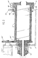
- FIG. 1 Most of the structure of the oven is formed by a enclosure 1 composed of a cylindrical shell 2 united to a support flange 3 and a casting flange 4, both disc-shaped.
- the support flange 3 is extended by a hollow shaft 5, coaxial with the ferrule 2 and occupied by an electrode 6 which extends over a much of the length of enclosure 1, depending on its axis, and darts the fusing agent electric arc toward another electrode 46, which passes through the flange of pour 4 at the location of a tap hole 56 central.
- the arc is radiated towards the material to be melted, which covers the internal face of the shell 2 in operation, when enclosure 1 is rotating.
- the second electrode 6 is removed before pouring the material fondue outside the enclosure 1.
- the shaft 5 is supported by a frame 7 by via a bearing 8. It is surrounded by a box 9 for distribution and collection of liquid cooling, ring-shaped, crossed at its top by a supply duct 10 and by a collection conduit 11.
- the box 9 is supported at its axial ends by a pair of bearings 12 and 13 which join it to the hollow shaft 5.
- Two pairs of seals 14, 15 and 16, 17 all extending between the shaft 5 and the box 9 -and framed by bearings 12 and 13- have to isolate the supply lines 10 and collecting 11 from each other and bearings 12 and 13.
- Enclosure 1 is made up of three layers full separated by superimposed channels forming the cooling system. We will see that these channels actually form a single channel in all of the enclosure 1.
- the support flange 3 is thus hollowed out a supply channel 18 and a collection channel 19 spouses, plans and circulars, and who extend by annular and concentric portions in tree 5.
- the canal supply 18 is partly occupied, in the flange 3, by a spiral 20 (clearly visible in FIG. 4) which transforms it into a spiral channel in which a flow centrifugal coolant is ensured thanks to the direction of rotation of the enclosure 1.
- the channels supply 18 and collection 19 end in the hollow shaft by grooves or circular channels 58 and 59 adjacent in which the conduits supply 10 and collection 11 open respectively: whatever the position of enclosure 1, cooling water circulation is therefore uninterrupted during the rotation. This construction appears fully in Figure 3.
- the ferrule 2 is itself hollowed out with a feed channel 21 and return channel 22 concentric and annular; return channel 22 is fully cleared but the supply channel 21 is occupied by a propeller 43 which transforms it into a channel helical in which the coolant gets sees imposed a flow directed towards the flange of flow 4 when the enclosure 1 rotates.
- Supply channels 21 and return 22 do not extend to the end of the shell 2 but end with holes, 23 and 24 respectively, on the side of the flange of the support 3, and 25 and 26 respectively on the side of the pouring flange 4. All of these holes 23 to 26 have a radial direction and form so elbows with channels 21 and 22.
- the orifices 23 and 24 therefore open onto the outer face of the casing 1 next to orifices 27 and 28 of the supply 18 and collection 19 channels of the support flange 3.
- the casting flange 4 is itself provided a supply channel 32 and a return channel 33 provided with respective holes 34 and 35 opening at its periphery and next to orifices 25 and 26. It suffices then add other hoses 36 and 37, respectively between the openings 25 and 34 and between the holes 26 and 35, so that the cooling is perfectly unified between supply and collection ducts 11, the supply and return channels 32 and 33 connecting at a junction 45 around the tap hole 56.
- return channel 33 otherwise planar and circular, is perfectly clear, while the supply channel 32, also planar, circular and parallel to the previous one, is occupied by a spiral 44 which imposes a centripetal movement on the liquid of cooling when speaker 1 is running: sound orientation is therefore opposite to that of spiral 20 the support flange 3.
- a flange 57 is linked to the shell 2, near of the casting flange 4, by bolts 47; she wears a ring gear 38 which meshes with a pinion 39 a motor 40 fixed to the frame 7. Furthermore, a bearing 41 is disposed between the flange 57 and the frame 7. Bearings 8 and 41 thus support perfectly the assembly constituted by enclosure 1 and the hollow shaft 5 which extends it, by its two extremities.
- the motor 40 drives the enclosure 1 in rotation via the ring gear 38 and flange 57.
- Bolts 47 are also used to assemble the pouring flange 4 to the shell 2; it is insulating bolts, because we want to establish a barrier to electricity flows and arc strikes between these two rooms. For this we insert a insulating circular packing 48, that the bolts 47 compress, between the faces opposite the shell 2 and of the casting flange 4; the hoop tubes 36 and 37 are also insulating, as is water sufficient cooling because it is demineralized.
- FIG. 2 illustrates a somewhat different.
- the electrodes 6 and 46 and the discs insulators 51 and 52 have been omitted from the representation to lighten it.
- the motor 40 is moved and takes the reference 40 '; it is located near the hollow shaft 5 and its pinion 39 'meshes with a toothed crown 38' built on the periphery of the support flange 3. De more, the latter is in one piece with the ferrule 2, and their supply channels 18 and 21, as well as their collection channels 19 and return channels 22, communicate directly, without opening or visible connection to outside.
- the pouring flange 4 remains separate from the shell 2 by the insulating circular lining 48, and so find the arched pipes 36 and 37 to connect their channels.
- Bearing 41 has disappeared and is replaced by a series of rollers 62 mounted on a crown 63 which rises from frame 7 and surrounds the ferrule 2 near the pouring flange 4, towards the location where the flange 57, also missing.
- a collar 64 support of the rollers 62 can however be added to the ferrule 2.
- the box 9 now carries the hollow shaft 5 and the enclosure 1. It is then screwed to the frame 7.
- the bearings 12 and 13 should now support a heavier weight and are advantageously replaced by stronger bearings such as 12 'and 13' roller bearings.
- the frame 7 is constructed to tilt to the tap and lower the tap hole 56.
Landscapes
- Engineering & Computer Science (AREA)
- Mechanical Engineering (AREA)
- General Engineering & Computer Science (AREA)
- Furnace Details (AREA)
- Muffle Furnaces And Rotary Kilns (AREA)
- Gasification And Melting Of Waste (AREA)
Claims (10)
- Drehschmelzofen mit einem Gehäuse (1), gebildet durch einen zylindrischen Mantel (2) zwischen zwei Flanschen (3, 4), und einem Kühlkreis des Gehäuses, dadurch gekennzeichnet,
dass der Mantel mit den Flanschen verbunden ist und dass es nur einen einzigen Kühlkreis (18, 19, 21, 22, 32, 33, 29, 30, 36, 37) gibt, von dem sich ein Teilstück im Mantel befindet, das mit einem Teilstück in jedem der Flansche verbunden ist. - Schmelzofen nach Anspruch 1, dadurch gekennzeichnet, dass der Kühlkreis im wesentlichen in das Gehäuse eingearbeitet ist bzw. es durchzieht.
- Schmelzofen nach Anspruch 2, dadurch gekennzeichnet, dass jeder der Teile des Kühlkreises zwei Schichten umfasst, die Sitze einer Gegenstrom-Strömung bilden.
- Schmelzofen nach Anspruch 1, dadurch gekennzeichnet, dass der Kühlkreis so konstruiert ist, dass eine Kühlflüssigkeitsströmung zirkuliert, wenn der Ofen sich dreht.
- Schmelzofen nach Anspruch 4, dadurch gekennzeichnet, dass das in dem Mantel befindliche Teilstück des Kühlkreises wenigstens teilweise einen spiralförmigen Kanal (21) bildet.
- Schmelzofen nach Anspruch 4, dadurch gekennzeichnet, dass die Teilstücke des Kühlkreises in den Flanschen wenigstens teilweise einen spiralförmigen Kanal (18, 32) bilden.
- Schmelzofen nach Anspruch 1, dadurch gekennzeichnet, dass die Teilstücke des Kühlkreises durch Rohrleitungen (29, 30, 36, 37) verbunden sind, die um die Verbindungsperipherie von dem Mantel zu den Flanschen herumführen.
- Schmelzofen nach Anspruch 1, dadurch gekennzeichnet, dass er eine an einem Flansch (3) befestigte Dreh- und Stützachse (5) des Ofens umfasst.
- Schmelzofen nach Anspruch 8, dadurch gekennzeichnet, dass die Drehachse durch Lager (8, 12', 13') getragen wird.
- Schmelzofen nach Anspruch 8, dadurch gekennzeichnet, dass der Kühlkreis sich in der Achse (5) erstreckt, wo er in wenigstens einem ringförmigen Kanal (58, 59) endet, an dem jeweils eine zur Achse senkrechte feste Leitung (10, 11) sich öffnet.
Applications Claiming Priority (2)
| Application Number | Priority Date | Filing Date | Title |
|---|---|---|---|
| FR9509462 | 1995-08-03 | ||
| FR9509462A FR2737554B1 (fr) | 1995-08-03 | 1995-08-03 | Four de fusion tournant |
Publications (2)
| Publication Number | Publication Date |
|---|---|
| EP0760456A1 EP0760456A1 (de) | 1997-03-05 |
| EP0760456B1 true EP0760456B1 (de) | 2000-06-28 |
Family
ID=9481685
Family Applications (1)
| Application Number | Title | Priority Date | Filing Date |
|---|---|---|---|
| EP96401717A Expired - Lifetime EP0760456B1 (de) | 1995-08-03 | 1996-08-01 | Drehschmelzofen |
Country Status (7)
| Country | Link |
|---|---|
| US (1) | US5711664A (de) |
| EP (1) | EP0760456B1 (de) |
| JP (1) | JPH09119778A (de) |
| KR (1) | KR100436176B1 (de) |
| CA (1) | CA2181533A1 (de) |
| DE (1) | DE69609022T2 (de) |
| FR (1) | FR2737554B1 (de) |
Families Citing this family (8)
| Publication number | Priority date | Publication date | Assignee | Title |
|---|---|---|---|---|
| US6105272A (en) * | 1998-06-22 | 2000-08-22 | Cabot Corporation | High temperature rotating vacuum kiln for heat treating solid particulate material under a vacuum |
| US6042370A (en) * | 1999-08-20 | 2000-03-28 | Haper International Corp. | Graphite rotary tube furnace |
| KR100619481B1 (ko) * | 2004-08-02 | 2006-09-08 | 이우범 | 사각형 바를 형성한 동방향 회전식 로터리 킬른 |
| CN101936652A (zh) * | 2010-09-05 | 2011-01-05 | 江苏金能环境科技有限公司 | 回转窑热端窑口保护罩 |
| US9550694B2 (en) | 2014-03-31 | 2017-01-24 | Corning Incorporated | Methods and apparatus for material processing using plasma thermal source |
| US9533909B2 (en) | 2014-03-31 | 2017-01-03 | Corning Incorporated | Methods and apparatus for material processing using atmospheric thermal plasma reactor |
| US9284210B2 (en) | 2014-03-31 | 2016-03-15 | Corning Incorporated | Methods and apparatus for material processing using dual source cyclonic plasma reactor |
| US20160200618A1 (en) | 2015-01-08 | 2016-07-14 | Corning Incorporated | Method and apparatus for adding thermal energy to a glass melt |
Family Cites Families (18)
| Publication number | Priority date | Publication date | Assignee | Title |
|---|---|---|---|---|
| FR527701A (fr) * | 1920-11-26 | 1921-10-29 | Andre Simon Cerf | Four tournant pour la fusion des métaux et alliages tels que bronze, laiton, étain et autres |
| US2702743A (en) * | 1948-08-12 | 1955-02-22 | Koppers Co Inc | Method and apparatus for preheating gaseous and vaporous reagents in powdered fuel gasification |
| FR1526999A (fr) * | 1967-02-20 | 1968-05-31 | Commissariat Energie Atomique | Four rotatif de fusion |
| CH512045A (de) * | 1970-02-04 | 1971-08-31 | Holderbank Man & Beratung Ag | Kühlvorrichtung für den Auslauf eines Drehtrommelofens |
| US3751220A (en) * | 1972-11-24 | 1973-08-07 | Allis Chalmers | Fluid delivery system for rotary kiln |
| FR2398261A1 (fr) * | 1977-07-20 | 1979-02-16 | Oconnor Chadwell | Four rotatif dont le tambour est constitue d'un ecran d'eau, destine a l'incineration de dechets |
| US4185984A (en) * | 1978-02-06 | 1980-01-29 | Union Carbide Corporation | Process for producing glass in a rotary furnace |
| DE3039212A1 (de) * | 1980-10-17 | 1982-05-19 | Metallgesellschaft Ag, 6000 Frankfurt | Verfahren zur thermischen behandlung von schuettguetern im drehrohrofen |
| US4443186A (en) * | 1982-04-14 | 1984-04-17 | The United States Of America As Represented By The United States Department Of Energy | Solar heated rotary kiln |
| US4785746A (en) * | 1985-04-25 | 1988-11-22 | Trw Inc. | Carbonaceous slurry combustor |
| DE3534991A1 (de) * | 1985-10-01 | 1987-04-02 | Gutehoffnungshuette Man | Drehrohrkuehler |
| US4836775A (en) * | 1985-12-23 | 1989-06-06 | Ppg Industries, Inc. | Air cooled rotary kiln collar |
| KR900002421Y1 (ko) * | 1987-04-28 | 1990-03-26 | 일양안티몬주식회사 | 안티모니 원광의 제련장치 |
| US4948365A (en) * | 1989-05-24 | 1990-08-14 | Zond Systems, Inc. | High-temperature, gas-burning furnace |
| US5000680A (en) * | 1990-02-15 | 1991-03-19 | Boliden Allis, Inc. | Rotary kiln |
| AU2449092A (en) * | 1991-08-09 | 1993-03-02 | New England Deaconess Hospital | A method of inducing hemoglobin synthesis in red blood cells and uses therefor |
| DE4419543C1 (de) * | 1994-06-03 | 1996-02-08 | Noell Gmbh | Drehrohr mit Mantelkühlung für Verbrennungsanlagen |
| US5515794A (en) * | 1995-01-23 | 1996-05-14 | Texaco Inc. | Partial oxidation process burner with recessed tip and gas blasting |
-
1995
- 1995-08-03 FR FR9509462A patent/FR2737554B1/fr not_active Expired - Fee Related
-
1996
- 1996-07-18 CA CA002181533A patent/CA2181533A1/en not_active Abandoned
- 1996-07-22 US US08/681,062 patent/US5711664A/en not_active Expired - Fee Related
- 1996-07-30 KR KR1019960031513A patent/KR100436176B1/ko not_active Expired - Fee Related
- 1996-08-01 EP EP96401717A patent/EP0760456B1/de not_active Expired - Lifetime
- 1996-08-01 DE DE69609022T patent/DE69609022T2/de not_active Expired - Fee Related
- 1996-08-05 JP JP8206015A patent/JPH09119778A/ja active Pending
Also Published As
| Publication number | Publication date |
|---|---|
| CA2181533A1 (en) | 1997-02-04 |
| FR2737554B1 (fr) | 1997-08-29 |
| DE69609022T2 (de) | 2001-02-22 |
| EP0760456A1 (de) | 1997-03-05 |
| JPH09119778A (ja) | 1997-05-06 |
| KR100436176B1 (ko) | 2004-11-06 |
| KR970011766A (ko) | 1997-03-27 |
| DE69609022D1 (de) | 2000-08-03 |
| FR2737554A1 (fr) | 1997-02-07 |
| US5711664A (en) | 1998-01-27 |
Similar Documents
| Publication | Publication Date | Title |
|---|---|---|
| EP0760456B1 (de) | Drehschmelzofen | |
| EP0780546B1 (de) | Zentrifugalölabscheider für ein Schmierungsgehäuse | |
| CA2235051C (fr) | Mandrin de bobineuse pour l'enroulement d'un produit en bande et son utilisation | |
| EP0182716B1 (de) | Anstreifring für eine Gasturbine | |
| EP0311506B1 (de) | Schmelztiegel für einen Induktionsofen | |
| EP0892152A1 (de) | Heiz- b.z.w. Kühleinrichtung für ein Gehäuse mit kreisförmigem Querschnitt | |
| EP1999019A1 (de) | System zum enteisen eines lufteinlassverkleidungsteils für einen turbomotor | |
| FR2481761A1 (fr) | Barriere thermique pour pompes centrifuges a haute temperature et sans presse-etoupe | |
| BE621060A (de) | ||
| CH627834A5 (fr) | Paroi refroidie d'un four a arc. | |
| KR100229977B1 (ko) | 냉각롤 | |
| FR2543654A1 (fr) | Methode et appareil pour lubrifier une transmission a engrenages | |
| EP0178981B1 (de) | Elektrodenanordnung für Metallschmelzbad | |
| FR2516597A1 (fr) | Dispositif annulaire de joint d'usure et d'etancheite refroidi par l'air pour aubage de roue de turbine a gaz ou de compresseur | |
| FR2846263A1 (fr) | Mandrin refroidi pour l'enroulement d'un produit en bande | |
| FR2533956A1 (fr) | Structure de paroi isolante sans mortier | |
| US3199158A (en) | Centrifugal furnace for fusion and casting under vacuum | |
| EP0006800A1 (de) | Mit flüssigem Metall gekühlter schneller Kernreaktor | |
| EP0713996B1 (de) | Dichtungsflansch für die innere Aufnahme von Rohrleitungen | |
| BE570543A (de) | ||
| FR2787563A1 (fr) | Echangeur de temperature annulaire | |
| CH590724A5 (en) | Mfg. rods and tubes from bundles of filaments - which are bonded by heat with precise timing of plasticising period | |
| RU2020237C1 (ru) | Устройство для подачи жидкости для форсуночного орошения зубков, в частности, холодной воды | |
| FR3138324A1 (fr) | Bride modulaire de refroidissement | |
| FR2536844A1 (fr) | Entree pour refroidisseur dans un four rotatif, notamment pour la fabrication de chaux et de ciment |
Legal Events
| Date | Code | Title | Description |
|---|---|---|---|
| PUAI | Public reference made under article 153(3) epc to a published international application that has entered the european phase |
Free format text: ORIGINAL CODE: 0009012 |
|
| AK | Designated contracting states |
Kind code of ref document: A1 Designated state(s): BE CH DE GB IT LI |
|
| 17P | Request for examination filed |
Effective date: 19970808 |
|
| GRAG | Despatch of communication of intention to grant |
Free format text: ORIGINAL CODE: EPIDOS AGRA |
|
| 17Q | First examination report despatched |
Effective date: 19990908 |
|
| GRAG | Despatch of communication of intention to grant |
Free format text: ORIGINAL CODE: EPIDOS AGRA |
|
| GRAH | Despatch of communication of intention to grant a patent |
Free format text: ORIGINAL CODE: EPIDOS IGRA |
|
| GRAH | Despatch of communication of intention to grant a patent |
Free format text: ORIGINAL CODE: EPIDOS IGRA |
|
| GRAA | (expected) grant |
Free format text: ORIGINAL CODE: 0009210 |
|
| AK | Designated contracting states |
Kind code of ref document: B1 Designated state(s): BE CH DE GB IT LI |
|
| REG | Reference to a national code |
Ref country code: CH Ref legal event code: EP |
|
| REF | Corresponds to: |
Ref document number: 69609022 Country of ref document: DE Date of ref document: 20000803 |
|
| ITF | It: translation for a ep patent filed | ||
| GBT | Gb: translation of ep patent filed (gb section 77(6)(a)/1977) |
Effective date: 20000905 |
|
| PLBE | No opposition filed within time limit |
Free format text: ORIGINAL CODE: 0009261 |
|
| STAA | Information on the status of an ep patent application or granted ep patent |
Free format text: STATUS: NO OPPOSITION FILED WITHIN TIME LIMIT |
|
| 26N | No opposition filed | ||
| REG | Reference to a national code |
Ref country code: GB Ref legal event code: IF02 |
|
| PGFP | Annual fee paid to national office [announced via postgrant information from national office to epo] |
Ref country code: DE Payment date: 20070824 Year of fee payment: 12 |
|
| PGFP | Annual fee paid to national office [announced via postgrant information from national office to epo] |
Ref country code: CH Payment date: 20070823 Year of fee payment: 12 |
|
| PGFP | Annual fee paid to national office [announced via postgrant information from national office to epo] |
Ref country code: GB Payment date: 20070801 Year of fee payment: 12 |
|
| PGFP | Annual fee paid to national office [announced via postgrant information from national office to epo] |
Ref country code: IT Payment date: 20070828 Year of fee payment: 12 |
|
| PGFP | Annual fee paid to national office [announced via postgrant information from national office to epo] |
Ref country code: BE Payment date: 20071018 Year of fee payment: 12 |
|
| REG | Reference to a national code |
Ref country code: CH Ref legal event code: PL |
|
| GBPC | Gb: european patent ceased through non-payment of renewal fee |
Effective date: 20080801 |
|
| PG25 | Lapsed in a contracting state [announced via postgrant information from national office to epo] |
Ref country code: LI Free format text: LAPSE BECAUSE OF NON-PAYMENT OF DUE FEES Effective date: 20080831 Ref country code: CH Free format text: LAPSE BECAUSE OF NON-PAYMENT OF DUE FEES Effective date: 20080831 |
|
| PG25 | Lapsed in a contracting state [announced via postgrant information from national office to epo] |
Ref country code: BE Free format text: LAPSE BECAUSE OF NON-PAYMENT OF DUE FEES Effective date: 20080831 |
|
| PG25 | Lapsed in a contracting state [announced via postgrant information from national office to epo] |
Ref country code: IT Free format text: LAPSE BECAUSE OF NON-PAYMENT OF DUE FEES Effective date: 20080801 Ref country code: DE Free format text: LAPSE BECAUSE OF NON-PAYMENT OF DUE FEES Effective date: 20090303 |
|
| PG25 | Lapsed in a contracting state [announced via postgrant information from national office to epo] |
Ref country code: GB Free format text: LAPSE BECAUSE OF NON-PAYMENT OF DUE FEES Effective date: 20080801 |