EP0760199B2 - Pneumatische Drillmaschine - Google Patents
Pneumatische Drillmaschine Download PDFInfo
- Publication number
- EP0760199B2 EP0760199B2 EP96112254A EP96112254A EP0760199B2 EP 0760199 B2 EP0760199 B2 EP 0760199B2 EP 96112254 A EP96112254 A EP 96112254A EP 96112254 A EP96112254 A EP 96112254A EP 0760199 B2 EP0760199 B2 EP 0760199B2
- Authority
- EP
- European Patent Office
- Prior art keywords
- seed drill
- rotary comb
- drivable
- hydraulic
- switchover
- Prior art date
- Legal status (The legal status is an assumption and is not a legal conclusion. Google has not performed a legal analysis and makes no representation as to the accuracy of the status listed.)
- Expired - Lifetime
Links
Images


Classifications
-
- A—HUMAN NECESSITIES
- A01—AGRICULTURE; FORESTRY; ANIMAL HUSBANDRY; HUNTING; TRAPPING; FISHING
- A01C—PLANTING; SOWING; FERTILISING
- A01C5/00—Making or covering furrows or holes for sowing, planting or manuring
- A01C5/06—Machines for making or covering drills or furrows for sowing or planting
- A01C5/066—Devices for covering drills or furrows
-
- A—HUMAN NECESSITIES
- A01—AGRICULTURE; FORESTRY; ANIMAL HUSBANDRY; HUNTING; TRAPPING; FISHING
- A01C—PLANTING; SOWING; FERTILISING
- A01C19/00—Arrangements for driving working parts of fertilisers or seeders
- A01C19/02—Arrangements for driving working parts of fertilisers or seeders by a motor
-
- A—HUMAN NECESSITIES
- A01—AGRICULTURE; FORESTRY; ANIMAL HUSBANDRY; HUNTING; TRAPPING; FISHING
- A01C—PLANTING; SOWING; FERTILISING
- A01C7/00—Sowing
- A01C7/08—Broadcast seeders; Seeders depositing seeds in rows
- A01C7/081—Seeders depositing seeds in rows using pneumatic means
Definitions
- the invention relates to a pneumatic seed drill according to the preamble of the claim 1.
- Such pneumatic seed drills are in known in practice (see DE-A-4238019).
- This pneumatic Drills have a hydraulic system with a hydraulic pump and a hydraulic motor to drive a blower and other hydraulically drivable and actuatable elements.
- Another seed drill is for example known from DE-OS 42 35 524. With this seed drill is behind the coulters over an oil engine drivable rotor harrow arranged.
- the invention is based on the object here remedy in a simple way.
- the rotor harrow by means of an excavation device lowerable into its working position and in at least one upper position can be raised. As a result this measure can also be done in a simple manner a blockage of the rotor harrow or one itself Avoiding blockage of the rotor harrow avoided become.
- the excavation device is via an actuating device for brief lifting and subsequent lowering can be actuated.
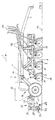
- the pneumatic seed drill is a direct seed drill for the use of seeds in unprepared seeds Floors provided.
- the direct seeder has the base frame 1.
- On the base frame 1 are seen in the direction of travel 2 on the back 3 in Distance to each other via the two support arms 4 Impellers 5 arranged.
- On the front 6 of the Base frame 1 is the drawbar 7, the the trailer coupling of a tractor or over a special coupling device to the lower links of the To connect a three-point linkage on a tractor is. As a result, part of the weight of the seeder transferred to the rear wheels of the agricultural tractor.
- On the base frame 1 are coulter frame 8 provided to the trained as chisel coulters 9 Coulters over parallelogram handlebar 10 in the height direction are arranged movably.
- the coulters 9 are in four rows in a row on gap and staggered. Behind the coulters 9 depth guide and pressure rollers 11 are arranged, the penetration depth of the coulters 9 into the soil 12 determine.
- the dosing tank 13 of the pneumatic Drill On the back 3 of the direct seeder is above the impellers 5 the metering tank 13 of the pneumatic Drill arranged.
- the dosing tank 13 has a known and therefore not shown Dosing system.
- This dosing system is on a pneumatic conveyor 14, the one Fan 15 has connected.
- the transport line 16 of the conveyor 14 leads to the distributor head 17, on the front 6 in front of the Base frame 1 is arranged. From this distribution head 17 leads to each seed coulter 9 a seed line 18, so that the seed in the from the coulters 9 in the Soil 12 torn seed furrows 19 are deposited can.
- Rotor harrow 23 On the back 3 of the seeder is on the Support arms 4 on the three-point coupling 20, the two lower links 21 and the length-adjustable Has upper link 22, the divided into three sections Rotor harrow 23 arranged. Each section of the Rotor harrow 23 is driven by an oil motor 24, 24 ', 24 " rotating via the chain drive 25 in the direction of arrow 26 driven. The rotor harrow 23 has tines 27.
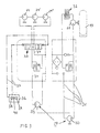
- the rotor harrow 23 and the blower 15 associated oil motors 24,24 ', 24 "and 28 from the pump 29, which on the Tractor PTO attached and as a tandem pump is trained, driven.
- the hydraulic pump 30 the tandem pump 29 is connected via lines 31 to the Hydraulic motor 28 of the blower 15 connected.
- an oil cooler 32 is arranged in the Hydraulic line 31 from the hydraulic motor 28.
- the other hydraulic pump 33 of the tandem pump 29 is via lines 34 to the hydraulic motors 24,24 ', 24 "of the rotor harrow 23 connected.
- the electrically operated Switchover valve 35 is with the switchover device 36 connected via the electrical lines 37.
- Pressing the button 38 switches the valve 35, so that about the hydraulic motors 24,24 'and 24 " Rotor harrow 23 is driven in the direction of arrow 26. If there is too much straw in front of the and the accumulation of plant remains or stones is done by briefly pressing the shift key 39 of the Switching device 36, the valve 35 switched, so that the harrow 23 opposite to the direction of the arrow 26 rotates.
- FIG. 4 shows another hydraulic circuit diagram to the work of the rotor harrow 23 during the To be able to temporarily interrupt use.
- the hydraulic cylinder 34 ' arranged, by means of which the rotor harrow 23 from its working position can be raised so that that accumulated in front of the rotor harrow 23 Parts of straw and plants as well as stones under the raised one Rotor harrow 23 can pass through.
- the rotor harrow 23 passes these clusters the rotor harrow 23 is activated by actuating the control unit, on which the hydraulic cylinder 34 'via a Line 41 is connected back to its working position lowered.
- the control valve of the rotor harrow raised and then lowered again.
Landscapes
- Life Sciences & Earth Sciences (AREA)
- Soil Sciences (AREA)
- Environmental Sciences (AREA)
- Soil Working Implements (AREA)
- Sowing (AREA)
Description
- Fig.1
- eine pneumatische Drillmaschine in Seitenansicht und in Prinzipdarstellung,
- Fig.2
- den Hydraulikschaltplan für die Tandempumpe der Hydraulikanlage der Drillmaschine gemäß Fig. 1.
- Fig.3
- einen weiteren Hydraulikschaltplan für die Tandempumpe der Hydraulikanlage der Drillmaschine gemäß Fig.1 und
- Fig.4
- einen weiteren Hydraulikschaltplan für eine andere Hydraulikanlage der Drillmaschine gemäß Fig.1.
Claims (4)
- Drillmaschine zum Ausbringen des Saatgutes im Direktsaatverfahren mit einem Rahmen, Vorratsbehälter, mehrere in Querreihen und auf Lücke zueinander angeordneten Säscharen und zumindest einem hinter den Säscharen angeordneten, um eine quer zur Fahrtrichtung verlaufende Achse über einen Ölmotor rotierend antreibbaren Rotorstriegel, der während der Arbeit vorzugsweise derart antreibbar ist, daß er auf seiner Unterseite in Fahrtrichtung rotiert, dadurch gekennzeichnet, daß die Arbeit des Rotorstriegels (23) während des Einsatzes zeitweise unterbrechbar ist, wobei eine Umschalteinrichtung (36) vorgesehen ist, mittels welcher der Rotorstriegel (23) kurzzeitig in entgegengesetzter Richtung antreibbar ist.
- Drillmaschine nach Anspruch 1, dadurch gekennzeichnet, daß die Umschalteinrichtung (36) eine von Hand zu betätigende Umschalttaste (39) aufweist.
- Drillmaschine nach Anspruch 1, dadurch gekennzeichnet, daß der Rotorstriegel (23) mittels einer Aushubeinrichtung (20) in seine Arbeitsposition absenkbar und in zumindest eine obere Position anhebbar ist.
- Drillmaschine nach Anspruch 3, dadurch gekennzeichnet, daß die Aushubeinrichtung (20) über eine Betätigungseinrichtung zum kurzzeitigen Anheben und anschließendem Absenken betätigbar ist.
Applications Claiming Priority (4)
| Application Number | Priority Date | Filing Date | Title |
|---|---|---|---|
| DE19531646 | 1995-08-29 | ||
| DE1995131644 DE19531644A1 (de) | 1995-08-29 | 1995-08-29 | Drillmaschine |
| DE19531644 | 1995-08-29 | ||
| DE1995131646 DE19531646A1 (de) | 1995-08-29 | 1995-08-29 | Pneumatische Drillmaschine |
Publications (3)
| Publication Number | Publication Date |
|---|---|
| EP0760199A1 EP0760199A1 (de) | 1997-03-05 |
| EP0760199B1 EP0760199B1 (de) | 1999-03-17 |
| EP0760199B2 true EP0760199B2 (de) | 2002-01-30 |
Family
ID=26018073
Family Applications (1)
| Application Number | Title | Priority Date | Filing Date |
|---|---|---|---|
| EP96112254A Expired - Lifetime EP0760199B2 (de) | 1995-08-29 | 1996-07-30 | Pneumatische Drillmaschine |
Country Status (2)
| Country | Link |
|---|---|
| EP (1) | EP0760199B2 (de) |
| DE (1) | DE59601442D1 (de) |
Families Citing this family (4)
| Publication number | Priority date | Publication date | Assignee | Title |
|---|---|---|---|---|
| US6460623B1 (en) | 2000-10-20 | 2002-10-08 | Caterpillar Inc. | Hydraulic system providing down force on a work implement |
| DE102005045242A1 (de) * | 2005-09-22 | 2007-04-12 | Rabe Agri Gmbh | Landwirtschaftliche Gerätekombination, insbesondere zum Ausbringen von Verteilgütern |
| CN109673188B (zh) * | 2019-01-24 | 2022-08-19 | 山西省交通环境保护中心站(有限公司) | 一种高速公路植被恢复辅助装置 |
| DE102019118149A1 (de) * | 2019-07-04 | 2021-01-07 | Amazonen-Werke H. Dreyer Gmbh & Co. Kg | Sämaschine |
Citations (1)
| Publication number | Priority date | Publication date | Assignee | Title |
|---|---|---|---|---|
| EP0262285B1 (de) † | 1986-10-02 | 1991-08-21 | Robert M. Torras | Mäher mit Pumpen in Tandemanordnung |
Family Cites Families (4)
| Publication number | Priority date | Publication date | Assignee | Title |
|---|---|---|---|---|
| DE3513739A1 (de) * | 1985-04-17 | 1986-10-23 | Rauch Landmaschinenfabrik GmbH, 7573 Sinzheim | Vorrichtung zum streuen von duenger |
| DE3707739A1 (de) * | 1987-03-11 | 1988-09-22 | Amazonen Werke Dreyer H | Hydraulikanlage fuer den antrieb eines streugeraetes |
| DE4235524A1 (de) | 1992-09-04 | 1994-03-10 | Amazonen Werke Dreyer H | Direktsaatverfahren zum Einbringen von Saatgut in den Boden |
| DE4238019C2 (de) * | 1992-11-11 | 1998-11-12 | Rauch Landmaschfab Gmbh | Landwirtschaftliche Gerätekombination mit einer pneumatischen Sämaschine und einer Bodenbearbeitungsmaschine |
-
1996
- 1996-07-30 EP EP96112254A patent/EP0760199B2/de not_active Expired - Lifetime
- 1996-07-30 DE DE59601442T patent/DE59601442D1/de not_active Expired - Fee Related
Patent Citations (1)
| Publication number | Priority date | Publication date | Assignee | Title |
|---|---|---|---|---|
| EP0262285B1 (de) † | 1986-10-02 | 1991-08-21 | Robert M. Torras | Mäher mit Pumpen in Tandemanordnung |
Non-Patent Citations (2)
| Title |
|---|
| "Dominator", brochure by CLAAS, 1986 † |
| "Hydrauliek in de landbouwmechanisatie", Ir.B.C.P.M. van Straelen, 18.th Edition, May 1990 † |
Also Published As
| Publication number | Publication date |
|---|---|
| EP0760199B1 (de) | 1999-03-17 |
| DE59601442D1 (de) | 1999-04-22 |
| EP0760199A1 (de) | 1997-03-05 |
Similar Documents
| Publication | Publication Date | Title |
|---|---|---|
| DE112006000110B4 (de) | Kombinierte landwirtschaftliche Maschine | |
| EP0049330B1 (de) | Verfahren zum Ausbringen von Saatgut, Herrichten eines Saatbettes und Gerätekombination zur Verfahrensdurchführung | |
| US3367293A (en) | Landscaping implement | |
| EP0172358B1 (de) | Gerätekombination zur Bodenlockerung und Saatbettherrichtung | |
| DE4238019A1 (de) | Pneumatische Sämaschine und landwirtschaftliche Gerätekombination mit einer solchen | |
| DD297298A5 (de) | Vorrichtung zum einbringen von samen in den boden | |
| EP0760199B2 (de) | Pneumatische Drillmaschine | |
| EP0358947B1 (de) | Säschare in Wirkverbindung mit einer Bodenwalze | |
| EP0193804B1 (de) | Verfahren für die Aussaat von Nutzpflanzensaatgut | |
| DE3105641C2 (de) | ||
| DE68903856T2 (de) | Mechanisch angetriebenes bodenbearbeitungsgeraet. | |
| DD235992A5 (de) | Arbeitsverfahren zur aufbereitung als ackerbodens sowie eine geraetekombination zur durchfuehrung des verfahrens | |
| DE4325469A1 (de) | Verfahren und Maschinen/Gerätekombination zur Verfahrensdurchführung, gebildet aus einem Mähdrescher, einem Bodenbearbeitungsgerät und einem Saatgut-Sägerät | |
| DE2839601C2 (de) | ||
| DE68914260T2 (de) | Landwirtschaftliche Säeinrichtung. | |
| EP0327869B1 (de) | Geschlossene Bestellkombination | |
| EP0081222A1 (de) | Bestell-Schlepper | |
| DE3143408A1 (de) | Geraetekombination zur bodenlockerung und saatbettherrichtung | |
| EP0214369B1 (de) | Gerätekombination zum Ausbringen von Saatgut | |
| EP0216003A2 (de) | Verfahren und Gerätesystem zur Bodenlockerung, Saatbettherrichtung und Bestellung | |
| DE19531644A1 (de) | Drillmaschine | |
| DE2842294A1 (de) | Geraetekombination zur bodenlockerung und saatbettherrichtung | |
| DE3228891A1 (de) | Geraetekombination zur bodenlockerung und saatbettherrichtung | |
| DE3533819C2 (de) | ||
| DE29814121U1 (de) | Vorauflaufmarkierung für eine Drillmaschine |
Legal Events
| Date | Code | Title | Description |
|---|---|---|---|
| PUAI | Public reference made under article 153(3) epc to a published international application that has entered the european phase |
Free format text: ORIGINAL CODE: 0009012 |
|
| AK | Designated contracting states |
Kind code of ref document: A1 Designated state(s): DE FR GB |
|
| 17P | Request for examination filed |
Effective date: 19970509 |
|
| GRAG | Despatch of communication of intention to grant |
Free format text: ORIGINAL CODE: EPIDOS AGRA |
|
| GRAG | Despatch of communication of intention to grant |
Free format text: ORIGINAL CODE: EPIDOS AGRA |
|
| GRAH | Despatch of communication of intention to grant a patent |
Free format text: ORIGINAL CODE: EPIDOS IGRA |
|
| 17Q | First examination report despatched |
Effective date: 19980824 |
|
| GRAH | Despatch of communication of intention to grant a patent |
Free format text: ORIGINAL CODE: EPIDOS IGRA |
|
| GRAA | (expected) grant |
Free format text: ORIGINAL CODE: 0009210 |
|
| AK | Designated contracting states |
Kind code of ref document: B1 Designated state(s): DE FR GB |
|
| PG25 | Lapsed in a contracting state [announced via postgrant information from national office to epo] |
Ref country code: FR Free format text: LAPSE BECAUSE OF NON-PAYMENT OF DUE FEES Effective date: 19990317 |
|
| GBT | Gb: translation of ep patent filed (gb section 77(6)(a)/1977) |
Effective date: 19990319 |
|
| REF | Corresponds to: |
Ref document number: 59601442 Country of ref document: DE Date of ref document: 19990422 |
|
| ET | Fr: translation filed | ||
| PGFP | Annual fee paid to national office [announced via postgrant information from national office to epo] |
Ref country code: FR Payment date: 19990730 Year of fee payment: 4 |
|
| PLBI | Opposition filed |
Free format text: ORIGINAL CODE: 0009260 |
|
| PLBF | Reply of patent proprietor to notice(s) of opposition |
Free format text: ORIGINAL CODE: EPIDOS OBSO |
|
| 26 | Opposition filed |
Opponent name: MAASLAND N.V. Effective date: 19991215 |
|
| PLBF | Reply of patent proprietor to notice(s) of opposition |
Free format text: ORIGINAL CODE: EPIDOS OBSO |
|
| PGFP | Annual fee paid to national office [announced via postgrant information from national office to epo] |
Ref country code: GB Payment date: 20000504 Year of fee payment: 5 |
|
| REG | Reference to a national code |
Ref country code: FR Ref legal event code: ST |
|
| PLAW | Interlocutory decision in opposition |
Free format text: ORIGINAL CODE: EPIDOS IDOP |
|
| PG25 | Lapsed in a contracting state [announced via postgrant information from national office to epo] |
Ref country code: GB Free format text: LAPSE BECAUSE OF NON-PAYMENT OF DUE FEES Effective date: 20010730 |
|
| PLAW | Interlocutory decision in opposition |
Free format text: ORIGINAL CODE: EPIDOS IDOP |
|
| PUAH | Patent maintained in amended form |
Free format text: ORIGINAL CODE: 0009272 |
|
| STAA | Information on the status of an ep patent application or granted ep patent |
Free format text: STATUS: PATENT MAINTAINED AS AMENDED |
|
| 27A | Patent maintained in amended form |
Effective date: 20020130 |
|
| AK | Designated contracting states |
Kind code of ref document: B2 Designated state(s): DE FR GB |
|
| GBPC | Gb: european patent ceased through non-payment of renewal fee |
Effective date: 20010730 |
|
| PGFP | Annual fee paid to national office [announced via postgrant information from national office to epo] |
Ref country code: DE Payment date: 20020726 Year of fee payment: 7 |
|
| EN | Fr: translation not filed | ||
| PG25 | Lapsed in a contracting state [announced via postgrant information from national office to epo] |
Ref country code: DE Free format text: LAPSE BECAUSE OF NON-PAYMENT OF DUE FEES Effective date: 20040203 |