EP0758035B1 - Verfahren zum Einbringen eines Bodenankers und entsprechender Bodenanker - Google Patents
Verfahren zum Einbringen eines Bodenankers und entsprechender Bodenanker Download PDFInfo
- Publication number
- EP0758035B1 EP0758035B1 EP96202172A EP96202172A EP0758035B1 EP 0758035 B1 EP0758035 B1 EP 0758035B1 EP 96202172 A EP96202172 A EP 96202172A EP 96202172 A EP96202172 A EP 96202172A EP 0758035 B1 EP0758035 B1 EP 0758035B1
- Authority
- EP
- European Patent Office
- Prior art keywords
- anchor body
- anchor
- ground
- line
- proximal end
- Prior art date
- Legal status (The legal status is an assumption and is not a legal conclusion. Google has not performed a legal analysis and makes no representation as to the accuracy of the status listed.)
- Expired - Lifetime
Links
- 238000000034 method Methods 0.000 title claims abstract description 13
- 238000004873 anchoring Methods 0.000 claims description 16
- 230000008878 coupling Effects 0.000 claims description 7
- 238000010168 coupling process Methods 0.000 claims description 7
- 238000005859 coupling reaction Methods 0.000 claims description 7
- 229910000831 Steel Inorganic materials 0.000 description 3
- 239000010959 steel Substances 0.000 description 3
- 230000002093 peripheral effect Effects 0.000 description 1
- 230000008719 thickening Effects 0.000 description 1
Images
Classifications
-
- E—FIXED CONSTRUCTIONS
- E02—HYDRAULIC ENGINEERING; FOUNDATIONS; SOIL SHIFTING
- E02D—FOUNDATIONS; EXCAVATIONS; EMBANKMENTS; UNDERGROUND OR UNDERWATER STRUCTURES
- E02D5/00—Bulkheads, piles, or other structural elements specially adapted to foundation engineering
- E02D5/74—Means for anchoring structural elements or bulkheads
- E02D5/80—Ground anchors
- E02D5/803—Ground anchors with pivotable anchoring members
-
- E—FIXED CONSTRUCTIONS
- E02—HYDRAULIC ENGINEERING; FOUNDATIONS; SOIL SHIFTING
- E02D—FOUNDATIONS; EXCAVATIONS; EMBANKMENTS; UNDERGROUND OR UNDERWATER STRUCTURES
- E02D5/00—Bulkheads, piles, or other structural elements specially adapted to foundation engineering
- E02D5/74—Means for anchoring structural elements or bulkheads
- E02D5/80—Ground anchors
- E02D5/801—Ground anchors driven by screwing
Definitions
- the invention relates to a method as defined in the first part of claim 1.
- the method is, in fact, completed and the anchoring line extends alongside the anchor body and the extension tubes, if any, and through the ground upwards. There is no mention of disconnecting an extension tube after the anchor body has arrived at the desired depth.
- the method according to the present invention distinguishes from the well-known method by the features defined in the second part of claim 1.
- the axis of the anchor body will become positioned at an angle relative to the line and this gives an increase of the resistance to pull out.
- the ultimate resistance to pull out of the anchor body will be the higher, the more the pull load on the line is increased and thus the angle between the axis of the anchor body and the line will become larger.
- DE-U-85 19 054 discloses a method, whereby an elongate anchor body is introduced into the ground by connecting one end of it to the distal end of an extension rod and applying hammerblows onto the proximal end of the extension rod.
- An anchoring line extends alongside the anchor extension tube assembly and is fastened with its distal end to the anchor body at a pivot point that is positioned about midway between the ends of the anchor body.
- the extension rod is removed by unscrewing.
- the invention also relates to a ground anchor as defined in the first part of claim 2.
- the improved anchor according to the present invention is characterized by the features defined in the second part of claim 2.
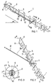
- the anchor shown in fig. 1 of the drawing has to be driven into the ground under an elevational angle ⁇ e.g. 25-40°. It comprises an anchor body 1 in the form of a core rod 2 that is provided with a screw blade 3 in a well-known manner and ends at its distal end into a beveled frog 4.
- a longitudinal recess 7 is provided in the surface of the core rod 2 to accomodate a steel wire cable 8.
- the longitudinal recess 7 extends through a part of the length of the core rod, vz. from the proximal end of it (positioned within the coupling sleeve) up to a location X at the cross sectional plane III-III. From the location X the longitudinal recess 7 continues in the form of a passage 7a that extends through and obliquely to the opposite longitudinal side of the core rod 2.
- the distal end portion of the cable 8, that bends inwardly through said passage 7a is anchored in the widened end 7b of the passage 7a, e.g. by means of a thickening 9 swaged on the distal end of it.
- the screw blade 3 is interrupted at the longitudinal recess 7 by radially outwardly extending slits 10, which communicate with said recess and merge into the peripheral edge of the screw blade 3.
- the coupling sleeve 5 is provided with a longitudinal slit 11 that corresponds with the longitudinal recess 7.
- the cable 8 is locked in place within the longitudinal recess 7 and within the extension tube 6 screwed into the coupling sleeve 5 respectively.
- the cable leaves the extension tube 6 at the proximal end (not shown in the drawing) of said extension tube.
- the anchor is driven in a well-known manner, under the desired elevational angle ⁇ into the ground by rotating it in the arrow direction A.
- the extension rod 6 is unscrewed by rotating it in a direction opposite to the arrow A, and then pulled out of the ground, after which a pulling load is applied at the proximal end of the steel wire cable 8 (see fig. 2) under the influence of which the anchor body 1 is turned about the anchoring location X in the arrow direction B, while allowing the cable 8 to move out of its seat 7 and through the longitudinal slit 11 and the radial slits 10 outwardly.
- the ultimate resistance to pull out of the anchor body will become higher, as the pull load on the steel wire cable (functioning as a permanent anchoring line) is increased and thereby the angle ⁇ between the axis of the anchor body 1 and the line 8 will increase.
- the coupling sleeve 5 may be beveled at its proximal end 5a, as seen rearwardly and opposite to the direction B. This facilitates the tilting movement of the anchor body 1 in the arrow direction.
Landscapes
- Engineering & Computer Science (AREA)
- Structural Engineering (AREA)
- Life Sciences & Earth Sciences (AREA)
- General Life Sciences & Earth Sciences (AREA)
- Mining & Mineral Resources (AREA)
- Paleontology (AREA)
- Civil Engineering (AREA)
- General Engineering & Computer Science (AREA)
- Piles And Underground Anchors (AREA)
- Joining Of Building Structures In Genera (AREA)
- Conveying And Assembling Of Building Elements In Situ (AREA)
Claims (7)
- Ein Verfahren zum Einbringen eines langgestreckten Bodenankerkörpers (1), der einen Kernabschnitt (2) und einen Schraubenblattabschnitt (3) aufweist, in den Boden, wobei das Verfahren die folgenden Schritte aufweist:gekennzeichnet durch die zusätzlichen Schritte von:Einschrauben des langgestreckten Ankerkörpers (1) in den Boden unter Verwendung einer Verlängerungsröhre (6), die mit dem proximalen Ende des Ankerkörpers (1) verbunden ist und dann gedreht wird, bis der Ankerkörper (1) eine gewünschte Tiefe erreicht hat;Befestigen einer Verankerungsleine (8) ausreichender Zugfestigkeit mit ihrem distalen Ende mit dem Ankerkörper (1) an einer Stelle (X), welche relativ zum Querschnitt des Ankerkörpers (1) exzentrisch und an einem bezüglich der Länge des letzteren zwischenliegenden Punktes liegt, wobei die Leine (8) so gehalten ist, daß sie sich von der Befestigungsstelle (X) entlang des proximalen Abschnittes des Ankerkörpers (1) nach oben erstreckt und weiterhin nach oben erstreckt, während der Ankerkörper eingeschraubt wird,bewirken, daß die Verankerungsleine (8) sich von der Stelle (X) an einer Position entlang des Kernabschnittes (2) des Ankerkörpers (1) in Richtung des proximalen Endes vom Ankerkörper (1) und von dem letzteren Ende in und durch die hiermit verbundene Verlängerungsröhre (6) erstreckt;Abschrauben der Verlängerungsröhre (6) vom Ankerkörper (1) und Entfernen hiervon von der Verankerungsleine (8), nachdem der Ankerkörper die gewünschte Tiefe erreicht hat;Aufbringen einer Zugbelastung auf das freie proximale Ende der Verankerungsleine (8), welche ausreichend ist, es der Verankerungsleine (8) zu ermöglichen, aus der entlang der Seite verlaufenden Position durch radiale Schlitze (10) auszutreten, welche in dem Schraubenblattabschnitt an der entlang der Seite verlaufenden Position ausgebildet sind, wodurch bewirkt wird, daß der Ankerkörper (1) im Boden eine Kippbewegung um die Befestigungsstelle (X) durchführt, wonach nach dieser Bewegung das proximale Ende der Verankerungsleine an der zu verankernden Struktur angebracht wird.
- Ein Bodenanker zur Verwendung mit dem Verfahren nach Anspruch 1, mit einem langgestreckten Ankerkörper (1), der einen Kernstab (2) mit zwei oder mehr Schraubenblätter (3) hat, mitdadurch gekennzeichnet, daßeiner Verlängerungsröhre (6), deren distales Ende mittels einer Kupplungshülse (5) entfernbar mit dem proximalen Ende des Kernstabes (2) des Ankerkörpers (1) verbunden ist,einer Verankerungsleine (8), deren distales Ende mit dem Ankerkörper (1) an einer Stelle (X) festgelegt ist, welche relativ zum Querschnitt des Ankerkörpers (1) exzentrisch und bezüglich der Länge des letzteren an einem Zwischenpunkt festgelegt ist,die Verankerungsleine (8) sich von der Befestigungsstelle (X) zuerst entlang des Kernstabs (2) des Ankerkörpers (1) in Richtung des proximalen Endes des letzteren und dann vom proximalen Ende des Kernstabs (2) in und durch die Verlängerungsröhre (6) erstreckt,daß die Verbindung zwischen dem Kernstab (2) und der Verlängerungsröhre (6) eine Schraubhülsenverbindung (5) ist, unddaß das Schraubenblatt oder die Schraubenblätter, welche an der Kernstablänge zwischen der Befestigungsstelle (X) und dem proximalen Ende des Kernstabs (2) angeordnet ist oder sind, radial nach außen in einer Ebene geschlitzt ist oder geschlitzt sind, welche im wesentlichen durch die Achse des Ankerkörpers (1) und durch die Befestigungsstelle (X) verläuft oder verlaufen, so daßdas Abschrauben und Entfernen der Verlängerungsröhre (6) es der Verankerungsleine ermöglicht, durch die radialen Schlitze (10) des Schraubenblattes oder der Schraubenblätter (3) nach außen auszutreten, wodurch es dem Ankerkörper (1) ermöglicht wird, um die Befestigungsstelle (X) relativ zu der Leine (8) zu verkippen.
- Ein Bodenanker nach Anspruch 2, dadurch gekennzeichnet, daß eine in Längsrichtung verlaufende Ausnehmung in der Oberfläche des Kernstabes vorgesehen ist, wobei sich die Ausnehmung vom proximalen Ende des letzteren hoch bis zur Befestigungsstelle erstreckt und als Sitz für die Leine dient.
- Ein Bodenanker nach Anspruch 3, dadurch gekennzeichnet, daß die in Längsrichtung verlaufende Ausnehmung (7) sich an der Befestigungsstelle (X) in Form eines Durchlasses (7a) fortsetzt, welcher sich schräg durch und in Richtung der gegenüberliegenden Seite des Kernstabes erstreckt, wobei das distale Ende der Leine an dem freien und aufgeweiteten Ende (7b) des Durchlasses (7a) festgelegt ist.
- Ein Bodenanker nach Anspruch 2 bis 4, dadurch gekennzeichnet, daß die Schlitze (10) in den Schraubenblättern (3) eine nach außen hin zunehmende Breite haben.
- Ein Bodenanker nach Anspruch 2 bis 5, dadurch gekennzeichnet, daß die Verbindungshülse (5) bleibend am proximalen Ende des Kernstabes (2) angebracht ist und mit einem Längsschlitz (11) in Fluchtung mit der Vertiefung (dem Sitz) (7) für die Leine (8) des Kernstabes (2) versehen ist.
- Ein Bodenanker nach Anspruch 6, dadurch gekennzeichnet, daß das proximale Ende (5a) der Verbindungshülse (5) abgeschrägt ist.
Applications Claiming Priority (2)
| Application Number | Priority Date | Filing Date | Title |
|---|---|---|---|
| NL1000941A NL1000941C2 (nl) | 1995-08-07 | 1995-08-07 | Werkwijze voor het aanbrengen van een trekanker in de bodem, alsmede daarbij te gebruiken anker. |
| NL1000941 | 1995-08-07 |
Publications (2)
| Publication Number | Publication Date |
|---|---|
| EP0758035A1 EP0758035A1 (de) | 1997-02-12 |
| EP0758035B1 true EP0758035B1 (de) | 2001-05-23 |
Family
ID=19761410
Family Applications (1)
| Application Number | Title | Priority Date | Filing Date |
|---|---|---|---|
| EP96202172A Expired - Lifetime EP0758035B1 (de) | 1995-08-07 | 1996-08-01 | Verfahren zum Einbringen eines Bodenankers und entsprechender Bodenanker |
Country Status (7)
| Country | Link |
|---|---|
| US (1) | US5930959A (de) |
| EP (1) | EP0758035B1 (de) |
| JP (1) | JPH11510230A (de) |
| AT (1) | ATE201470T1 (de) |
| DE (1) | DE69612921T2 (de) |
| NL (1) | NL1000941C2 (de) |
| WO (1) | WO1997006310A1 (de) |
Families Citing this family (7)
| Publication number | Priority date | Publication date | Assignee | Title |
|---|---|---|---|---|
| US6298611B1 (en) | 2000-05-17 | 2001-10-09 | James Oliver | Ground anchor with self-aligning compression cap |
| NL1016155C2 (nl) | 2000-09-12 | 2002-03-13 | Tijmen Van Halteren | Werkwijze voor het aanbrengen van een trekanker in de bodem, alsmede daarbij te gebruiken anker. |
| US6971209B1 (en) | 2003-04-28 | 2005-12-06 | Home Pride, Inc. | Stabilization system for an anchor and method of use thereof |
| NZ553958A (en) * | 2007-03-19 | 2008-04-30 | Miles Edward Moffat | Ground Anchor with cable guiding means for a loop of a winch cable |
| WO2009072067A1 (en) * | 2007-12-03 | 2009-06-11 | Douwie De Lange | An anchoring system |
| DE102008011869A1 (de) * | 2008-02-29 | 2009-09-10 | Peter Kellner | Schraubfundament |
| US20100223862A1 (en) * | 2009-03-06 | 2010-09-09 | Jacobus Nicolaas Smit | Multi-purpose auger-type anchoring system |
Family Cites Families (11)
| Publication number | Priority date | Publication date | Assignee | Title |
|---|---|---|---|---|
| US2603319A (en) * | 1952-07-15 | Ground anchor v | ||
| US1283246A (en) * | 1915-01-09 | 1918-10-29 | Allen Iron & Steel Company | Guy-anchor. |
| US1502965A (en) * | 1923-08-29 | 1924-07-29 | Seyler Lester John | Stake windlass |
| US2999572A (en) * | 1958-02-12 | 1961-09-12 | John D Hinckley | Earth anchor |
| US3089567A (en) * | 1961-09-29 | 1963-05-14 | Preformed Line Products Co | Appliance for linear bodies |
| US3710523A (en) * | 1971-08-03 | 1973-01-16 | J Taylor | Earth anchor |
| CA961237A (en) * | 1972-10-30 | 1975-01-21 | John D. Taylor | Earth anchor |
| US3797283A (en) * | 1972-11-06 | 1974-03-19 | A Honer | Device for locking movable objects to the ground |
| US4316350A (en) * | 1979-11-26 | 1982-02-23 | Watson Gary Q | Wing screw earth anchor |
| DE8519054U1 (de) * | 1985-07-01 | 1985-08-22 | Rockenfeller KG Befestigungselemente, 5912 Hilchenbach | Vorrichtung zur Verankerung von Zuggliedern in Erdreich |
| US4863137A (en) * | 1988-05-02 | 1989-09-05 | Cockman Boyce R | Post anchor |
-
1995
- 1995-08-07 NL NL1000941A patent/NL1000941C2/nl not_active IP Right Cessation
-
1996
- 1996-08-01 AT AT96202172T patent/ATE201470T1/de not_active IP Right Cessation
- 1996-08-01 DE DE69612921T patent/DE69612921T2/de not_active Expired - Fee Related
- 1996-08-01 EP EP96202172A patent/EP0758035B1/de not_active Expired - Lifetime
- 1996-08-02 WO PCT/NL1996/000314 patent/WO1997006310A1/en not_active Ceased
- 1996-08-02 JP JP9508339A patent/JPH11510230A/ja active Pending
- 1996-08-02 US US09/011,184 patent/US5930959A/en not_active Expired - Fee Related
Also Published As
| Publication number | Publication date |
|---|---|
| NL1000941C2 (nl) | 1997-02-11 |
| US5930959A (en) | 1999-08-03 |
| WO1997006310A1 (en) | 1997-02-20 |
| DE69612921T2 (de) | 2002-03-28 |
| ATE201470T1 (de) | 2001-06-15 |
| DE69612921D1 (de) | 2001-06-28 |
| EP0758035A1 (de) | 1997-02-12 |
| JPH11510230A (ja) | 1999-09-07 |
Similar Documents
| Publication | Publication Date | Title |
|---|---|---|
| US5927905A (en) | Method for applying a ground anchor into the ground and anchor to be used therewith | |
| CA2175673C (en) | Improvements in ground anchors | |
| CA2175674C (en) | Improvements in ground anchors | |
| DE60127781T2 (de) | Kabel mit einem Haken zur Fixierung eines atlanttoaxialen Gelenks und Anordnung zur Befestigung desselben | |
| EP0758035B1 (de) | Verfahren zum Einbringen eines Bodenankers und entsprechender Bodenanker | |
| US5031370A (en) | Coupled drive rods for installing ground anchors | |
| US4727693A (en) | Apparatus for anchoring a traction member in the ground | |
| US4477948A (en) | Dead-end messenger wire holder | |
| GB2354146A (en) | Fishing Tackle | |
| EP0216201B1 (de) | Vorrichtung zur Verankerung von Zuggliedern im Erdreich | |
| US5625984A (en) | Ground anchor | |
| GB2115856A (en) | Earth Anchor | |
| US20050150184A1 (en) | Anchoring device | |
| CN1151013C (zh) | 用于形状贴合地紧固的销钉的拆卸装置 | |
| GB2283510A (en) | Connecting means,e.g. for tendon and ground anchor | |
| US2359307A (en) | Hook for stump clearance | |
| EP0178489A1 (de) | Vorrichtung zur Lösbaren Befestigung einer mit einem Surfer verbindbaren Trapezleine am Gabelbaum eines Surfbrettes | |
| NL1016155C2 (nl) | Werkwijze voor het aanbrengen van een trekanker in de bodem, alsmede daarbij te gebruiken anker. | |
| WO2009072067A1 (en) | An anchoring system | |
| RU1814675C (ru) | Грунтовой анкер | |
| AU605389B2 (en) | Ribbed earth anchor | |
| NZ222173A (en) | Ground anchor | |
| EP1154091A1 (de) | Vorrichtung und Verfahren zur Verbindung von zwei Bewehrungstäben und Koppler dazu | |
| EP2597203A1 (de) | Grundanker | |
| NZ286568A (en) | Ground anchor: tapered, with external screw thread, annular boss at top end and an integral collar |
Legal Events
| Date | Code | Title | Description |
|---|---|---|---|
| PUAI | Public reference made under article 153(3) epc to a published international application that has entered the european phase |
Free format text: ORIGINAL CODE: 0009012 |
|
| AK | Designated contracting states |
Kind code of ref document: A1 Designated state(s): AT BE CH DE DK ES FR GB GR IE IT LI LU NL PT SE |
|
| 17P | Request for examination filed |
Effective date: 19970812 |
|
| GRAG | Despatch of communication of intention to grant |
Free format text: ORIGINAL CODE: EPIDOS AGRA |
|
| 17Q | First examination report despatched |
Effective date: 20000823 |
|
| GRAG | Despatch of communication of intention to grant |
Free format text: ORIGINAL CODE: EPIDOS AGRA |
|
| GRAG | Despatch of communication of intention to grant |
Free format text: ORIGINAL CODE: EPIDOS AGRA |
|
| GRAH | Despatch of communication of intention to grant a patent |
Free format text: ORIGINAL CODE: EPIDOS IGRA |
|
| GRAH | Despatch of communication of intention to grant a patent |
Free format text: ORIGINAL CODE: EPIDOS IGRA |
|
| GRAA | (expected) grant |
Free format text: ORIGINAL CODE: 0009210 |
|
| ITF | It: translation for a ep patent filed | ||
| AK | Designated contracting states |
Kind code of ref document: B1 Designated state(s): AT BE CH DE DK ES FR GB GR IE IT LI LU NL PT SE |
|
| REF | Corresponds to: |
Ref document number: 201470 Country of ref document: AT Date of ref document: 20010615 Kind code of ref document: T |
|
| REG | Reference to a national code |
Ref country code: CH Ref legal event code: EP |
|
| PGFP | Annual fee paid to national office [announced via postgrant information from national office to epo] |
Ref country code: IE Payment date: 20010615 Year of fee payment: 6 |
|
| REG | Reference to a national code |
Ref country code: CH Ref legal event code: NV Representative=s name: NOVAPAT INTERNATIONAL S.A. * NOVAPAT INTERNATIONAL |
|
| REF | Corresponds to: |
Ref document number: 69612921 Country of ref document: DE Date of ref document: 20010628 |
|
| REG | Reference to a national code |
Ref country code: IE Ref legal event code: FG4D |
|
| PGFP | Annual fee paid to national office [announced via postgrant information from national office to epo] |
Ref country code: FR Payment date: 20010809 Year of fee payment: 6 Ref country code: DE Payment date: 20010809 Year of fee payment: 6 Ref country code: CH Payment date: 20010809 Year of fee payment: 6 Ref country code: BE Payment date: 20010809 Year of fee payment: 6 Ref country code: AT Payment date: 20010809 Year of fee payment: 6 |
|
| ET | Fr: translation filed | ||
| PGFP | Annual fee paid to national office [announced via postgrant information from national office to epo] |
Ref country code: LU Payment date: 20010810 Year of fee payment: 6 |
|
| PG25 | Lapsed in a contracting state [announced via postgrant information from national office to epo] |
Ref country code: SE Free format text: LAPSE BECAUSE OF FAILURE TO SUBMIT A TRANSLATION OF THE DESCRIPTION OR TO PAY THE FEE WITHIN THE PRESCRIBED TIME-LIMIT Effective date: 20010823 Ref country code: PT Free format text: LAPSE BECAUSE OF FAILURE TO SUBMIT A TRANSLATION OF THE DESCRIPTION OR TO PAY THE FEE WITHIN THE PRESCRIBED TIME-LIMIT Effective date: 20010823 Ref country code: DK Free format text: LAPSE BECAUSE OF FAILURE TO SUBMIT A TRANSLATION OF THE DESCRIPTION OR TO PAY THE FEE WITHIN THE PRESCRIBED TIME-LIMIT Effective date: 20010823 |
|
| PG25 | Lapsed in a contracting state [announced via postgrant information from national office to epo] |
Ref country code: GR Free format text: LAPSE BECAUSE OF FAILURE TO SUBMIT A TRANSLATION OF THE DESCRIPTION OR TO PAY THE FEE WITHIN THE PRESCRIBED TIME-LIMIT Effective date: 20010824 |
|
| PGFP | Annual fee paid to national office [announced via postgrant information from national office to epo] |
Ref country code: NL Payment date: 20010831 Year of fee payment: 6 |
|
| PG25 | Lapsed in a contracting state [announced via postgrant information from national office to epo] |
Ref country code: ES Free format text: LAPSE BECAUSE OF FAILURE TO SUBMIT A TRANSLATION OF THE DESCRIPTION OR TO PAY THE FEE WITHIN THE PRESCRIBED TIME-LIMIT Effective date: 20011130 |
|
| REG | Reference to a national code |
Ref country code: GB Ref legal event code: IF02 |
|
| PLBE | No opposition filed within time limit |
Free format text: ORIGINAL CODE: 0009261 |
|
| STAA | Information on the status of an ep patent application or granted ep patent |
Free format text: STATUS: NO OPPOSITION FILED WITHIN TIME LIMIT |
|
| 26N | No opposition filed | ||
| PG25 | Lapsed in a contracting state [announced via postgrant information from national office to epo] |
Ref country code: LU Free format text: LAPSE BECAUSE OF NON-PAYMENT OF DUE FEES Effective date: 20020801 Ref country code: IE Free format text: LAPSE BECAUSE OF NON-PAYMENT OF DUE FEES Effective date: 20020801 Ref country code: AT Free format text: LAPSE BECAUSE OF NON-PAYMENT OF DUE FEES Effective date: 20020801 |
|
| PG25 | Lapsed in a contracting state [announced via postgrant information from national office to epo] |
Ref country code: LI Free format text: LAPSE BECAUSE OF NON-PAYMENT OF DUE FEES Effective date: 20020831 Ref country code: CH Free format text: LAPSE BECAUSE OF NON-PAYMENT OF DUE FEES Effective date: 20020831 Ref country code: BE Free format text: LAPSE BECAUSE OF NON-PAYMENT OF DUE FEES Effective date: 20020831 |
|
| PGFP | Annual fee paid to national office [announced via postgrant information from national office to epo] |
Ref country code: GB Payment date: 20030203 Year of fee payment: 7 |
|
| BERE | Be: lapsed |
Owner name: *VAN HALTEREN TIJMEN Effective date: 20020831 |
|
| PG25 | Lapsed in a contracting state [announced via postgrant information from national office to epo] |
Ref country code: NL Free format text: LAPSE BECAUSE OF NON-PAYMENT OF DUE FEES Effective date: 20030301 Ref country code: DE Free format text: LAPSE BECAUSE OF NON-PAYMENT OF DUE FEES Effective date: 20030301 |
|
| REG | Reference to a national code |
Ref country code: CH Ref legal event code: PL |
|
| PG25 | Lapsed in a contracting state [announced via postgrant information from national office to epo] |
Ref country code: FR Free format text: LAPSE BECAUSE OF NON-PAYMENT OF DUE FEES Effective date: 20030430 |
|
| NLV4 | Nl: lapsed or anulled due to non-payment of the annual fee |
Effective date: 20030301 |
|
| REG | Reference to a national code |
Ref country code: IE Ref legal event code: MM4A |
|
| REG | Reference to a national code |
Ref country code: FR Ref legal event code: ST |
|
| PG25 | Lapsed in a contracting state [announced via postgrant information from national office to epo] |
Ref country code: GB Free format text: LAPSE BECAUSE OF NON-PAYMENT OF DUE FEES Effective date: 20030801 |
|
| GBPC | Gb: european patent ceased through non-payment of renewal fee |
Effective date: 20030801 |
|
| PG25 | Lapsed in a contracting state [announced via postgrant information from national office to epo] |
Ref country code: IT Free format text: LAPSE BECAUSE OF NON-PAYMENT OF DUE FEES;WARNING: LAPSES OF ITALIAN PATENTS WITH EFFECTIVE DATE BEFORE 2007 MAY HAVE OCCURRED AT ANY TIME BEFORE 2007. THE CORRECT EFFECTIVE DATE MAY BE DIFFERENT FROM THE ONE RECORDED. Effective date: 20050801 |