EP0757537B1 - Mittels eines elektromotors betriebener staubsauger - Google Patents
Mittels eines elektromotors betriebener staubsauger Download PDFInfo
- Publication number
- EP0757537B1 EP0757537B1 EP95917960A EP95917960A EP0757537B1 EP 0757537 B1 EP0757537 B1 EP 0757537B1 EP 95917960 A EP95917960 A EP 95917960A EP 95917960 A EP95917960 A EP 95917960A EP 0757537 B1 EP0757537 B1 EP 0757537B1
- Authority
- EP
- European Patent Office
- Prior art keywords
- vacuum cleaner
- cleaner according
- electric motor
- housing
- sensor
- Prior art date
- Legal status (The legal status is an assumption and is not a legal conclusion. Google has not performed a legal analysis and makes no representation as to the accuracy of the status listed.)
- Expired - Lifetime
Links
- 230000001133 acceleration Effects 0.000 claims description 60
- 238000005096 rolling process Methods 0.000 claims description 14
- 230000004888 barrier function Effects 0.000 claims description 13
- 230000009467 reduction Effects 0.000 claims description 11
- 238000012544 monitoring process Methods 0.000 claims description 6
- 230000001960 triggered effect Effects 0.000 claims description 6
- 230000006870 function Effects 0.000 claims description 4
- 230000009849 deactivation Effects 0.000 claims description 3
- 238000001514 detection method Methods 0.000 claims description 3
- 230000004913 activation Effects 0.000 claims description 2
- 235000004443 Ricinus communis Nutrition 0.000 claims 1
- 238000010168 coupling process Methods 0.000 description 9
- 238000005859 coupling reaction Methods 0.000 description 9
- 230000033001 locomotion Effects 0.000 description 9
- 230000008878 coupling Effects 0.000 description 8
- 238000012549 training Methods 0.000 description 8
- 230000008859 change Effects 0.000 description 6
- 230000005291 magnetic effect Effects 0.000 description 6
- 238000004140 cleaning Methods 0.000 description 5
- 238000013461 design Methods 0.000 description 5
- 230000004044 response Effects 0.000 description 4
- 230000008901 benefit Effects 0.000 description 3
- 230000000903 blocking effect Effects 0.000 description 3
- 239000004020 conductor Substances 0.000 description 3
- 230000006835 compression Effects 0.000 description 2
- 238000007906 compression Methods 0.000 description 2
- 230000001276 controlling effect Effects 0.000 description 2
- 230000001419 dependent effect Effects 0.000 description 2
- 238000011161 development Methods 0.000 description 2
- 230000018109 developmental process Effects 0.000 description 2
- 230000000694 effects Effects 0.000 description 2
- 230000005284 excitation Effects 0.000 description 2
- 230000007935 neutral effect Effects 0.000 description 2
- 230000036316 preload Effects 0.000 description 2
- 230000001105 regulatory effect Effects 0.000 description 2
- 239000002689 soil Substances 0.000 description 2
- 230000007704 transition Effects 0.000 description 2
- 238000011144 upstream manufacturing Methods 0.000 description 2
- 235000014676 Phragmites communis Nutrition 0.000 description 1
- 238000004873 anchoring Methods 0.000 description 1
- 230000001680 brushing effect Effects 0.000 description 1
- 239000003990 capacitor Substances 0.000 description 1
- 238000011109 contamination Methods 0.000 description 1
- 230000003111 delayed effect Effects 0.000 description 1
- 238000010586 diagram Methods 0.000 description 1
- 238000004090 dissolution Methods 0.000 description 1
- 230000005294 ferromagnetic effect Effects 0.000 description 1
- 238000003780 insertion Methods 0.000 description 1
- 230000037431 insertion Effects 0.000 description 1
- 238000009413 insulation Methods 0.000 description 1
- 230000007246 mechanism Effects 0.000 description 1
- 239000002184 metal Substances 0.000 description 1
- 230000005405 multipole Effects 0.000 description 1
- 230000011514 reflex Effects 0.000 description 1
- 239000000725 suspension Substances 0.000 description 1
- 230000002123 temporal effect Effects 0.000 description 1
- 238000003466 welding Methods 0.000 description 1
Images





Classifications
-
- A—HUMAN NECESSITIES
- A47—FURNITURE; DOMESTIC ARTICLES OR APPLIANCES; COFFEE MILLS; SPICE MILLS; SUCTION CLEANERS IN GENERAL
- A47L—DOMESTIC WASHING OR CLEANING; SUCTION CLEANERS IN GENERAL
- A47L9/00—Details or accessories of suction cleaners, e.g. mechanical means for controlling the suction or for effecting pulsating action; Storing devices specially adapted to suction cleaners or parts thereof; Carrying-vehicles specially adapted for suction cleaners
- A47L9/28—Installation of the electric equipment, e.g. adaptation or attachment to the suction cleaner; Controlling suction cleaners by electric means
- A47L9/2836—Installation of the electric equipment, e.g. adaptation or attachment to the suction cleaner; Controlling suction cleaners by electric means characterised by the parts which are controlled
- A47L9/2842—Suction motors or blowers
-
- A—HUMAN NECESSITIES
- A47—FURNITURE; DOMESTIC ARTICLES OR APPLIANCES; COFFEE MILLS; SPICE MILLS; SUCTION CLEANERS IN GENERAL
- A47L—DOMESTIC WASHING OR CLEANING; SUCTION CLEANERS IN GENERAL
- A47L9/00—Details or accessories of suction cleaners, e.g. mechanical means for controlling the suction or for effecting pulsating action; Storing devices specially adapted to suction cleaners or parts thereof; Carrying-vehicles specially adapted for suction cleaners
- A47L9/28—Installation of the electric equipment, e.g. adaptation or attachment to the suction cleaner; Controlling suction cleaners by electric means
- A47L9/2805—Parameters or conditions being sensed
-
- A—HUMAN NECESSITIES
- A47—FURNITURE; DOMESTIC ARTICLES OR APPLIANCES; COFFEE MILLS; SPICE MILLS; SUCTION CLEANERS IN GENERAL
- A47L—DOMESTIC WASHING OR CLEANING; SUCTION CLEANERS IN GENERAL
- A47L9/00—Details or accessories of suction cleaners, e.g. mechanical means for controlling the suction or for effecting pulsating action; Storing devices specially adapted to suction cleaners or parts thereof; Carrying-vehicles specially adapted for suction cleaners
- A47L9/28—Installation of the electric equipment, e.g. adaptation or attachment to the suction cleaner; Controlling suction cleaners by electric means
- A47L9/2805—Parameters or conditions being sensed
- A47L9/281—Parameters or conditions being sensed the amount or condition of incoming dirt or dust
-
- A—HUMAN NECESSITIES
- A47—FURNITURE; DOMESTIC ARTICLES OR APPLIANCES; COFFEE MILLS; SPICE MILLS; SUCTION CLEANERS IN GENERAL
- A47L—DOMESTIC WASHING OR CLEANING; SUCTION CLEANERS IN GENERAL
- A47L9/00—Details or accessories of suction cleaners, e.g. mechanical means for controlling the suction or for effecting pulsating action; Storing devices specially adapted to suction cleaners or parts thereof; Carrying-vehicles specially adapted for suction cleaners
- A47L9/28—Installation of the electric equipment, e.g. adaptation or attachment to the suction cleaner; Controlling suction cleaners by electric means
- A47L9/2805—Parameters or conditions being sensed
- A47L9/2831—Motor parameters, e.g. motor load or speed
-
- H—ELECTRICITY
- H02—GENERATION; CONVERSION OR DISTRIBUTION OF ELECTRIC POWER
- H02P—CONTROL OR REGULATION OF ELECTRIC MOTORS, ELECTRIC GENERATORS OR DYNAMO-ELECTRIC CONVERTERS; CONTROLLING TRANSFORMERS, REACTORS OR CHOKE COILS
- H02P25/00—Arrangements or methods for the control of AC motors characterised by the kind of AC motor or by structural details
- H02P25/02—Arrangements or methods for the control of AC motors characterised by the kind of AC motor or by structural details characterised by the kind of motor
- H02P25/10—Commutator motors, e.g. repulsion motors
- H02P25/14—Universal motors
Definitions
- the invention relates to a Vacuum cleaner according to the preamble of claim 1.
- the object of the present invention is a generic Vacuum cleaner with regard to its usage properties to improve.
- the vacuum cleaner with overfloor work an attachment for example an electrically operated one Attachment brush
- an attachment for example an electrically operated one Attachment brush
- a handle and potentiometer combination on the device housing formed on a narrow side of the housing is. This can be the case, for example, when using the vacuum cleaner with an upstream suction hose or the like from Be an advantage.
- the vacuum cleaner on the on the Narrow side arranged handle worn and the power of the electric motor with that on the handle arranged potentiometer the respective Set needs accordingly.
- switching between an active and an inactive Setting potentiometer by pressing the inactive Setting potentiometer is done. This can, for example.
- an internal control the last actuated potentiometer registered recognizes this as active and the other setting potentiometer sets to inactive.
- This also applies to one Use of three or more potentiometers, where one is set active and the other inactive will. For example, from normal operation of the vacuum cleaner switched to an overfloor operation, so the User the handle arranged on the device housing. Is during normal operation on the setting potentiometer on the handle side a power value of the electric motor This setting potentiometer remains preset active until the user adjusts the potentiometer actuated on the handle on the housing. After that there is a switchover to the device housing side Potentiometer. The latter can now be used the power of the electric motor is reduced or also be enlarged.
- this setting potentiometer in brought an off position, so the suction power performing electric motor also turned off if one or more of the other potentiometers stand in an on position. This is because of it allows the latter to be inactive.
- the Training must be taken so that a switchover can be effected by removing the handle.
- a switch can be provided, which at plugged in the handle of the device Handle of the handle activated.
- the switch After deducting the switch causes this switch to toggle to the setting potentiometer arranged on the device housing, with which this is activated.
- an engine shutdown occurs.
- the electric motor is supplied with current through a running into the handle of the tool handle Cable, so here can be a plug-coupling combination be provided on the handle. Pulling the Device handle from the device housing causes also an interruption in the power supply, which leads to further handling of the vacuum cleaner a change of the live cable from the handle of the handle on the device housing.
- the blower motor sets only after engaging the power supply and one then actuate the housing-side Potentiometer. This also applies if For example, the power supply cable in the coupling of the Housing is inserted, the setting potentiometer on the housing is set to a maximum value. The electric motor remains switched off until that Adjustment potentiometer is moved, making an uncontrolled Started the electric motor counteracted is. When using a motor-driven attachment can the operation of the switch both Turning off the blower motor as well as turning off the Effect attachment motor. In an advantageous Training is provided that at a standstill of the device indicates a reduction in use the power of the electric motor to a minimum power he follows.
- the Reduction in the power of the electric motor continues in Dependence of a signal from a dirt sensor takes place.
- the previously described reduction in performance of the electric motor is therefore not only dependent on an indicated non-use of the vacuum cleaner, but also from a signal from a dirt sensor.
- the dirt sensor detects a range from low to normal pollution of the floor to be cared for, so the power of the electric motor is reduced to a minimal performance.
- the dirt sensor detects an area of increased pollution, so leads this leads to an increase in the power of the electric motor up to maximum power to cover the area covered nourishing soil.
- the display of the Not used can be realized in that this by monitoring a roller of the device is detectable. A corresponding sensor or scanner recorded during operation with the vacuum cleaner switched on the rotating movement of a roller of the device.
- this sensor gives a signal to reduce the power of the electric motor.
- the Detection of the rotational movement of a roller can, for example. be solved in that a toothed on the roller Sheet metal disc is attached, which is the magnetic field of a Hall sensor due to its ferromagnetic property influenced. This change in magnetic Field and thus the Hall voltage at the sensor can be electronic be evaluated so that through each tooth an impulse is generated.
- a fork or reflex light barrier can also be used.
- a toothed washer that coincides with the wheel rotates, the light beam from a light source is interrupted or reflected. That reflected or transmitted Light comes from a photosensitive element received and evaluated electrically, so that here too an impulse is generated by each tooth of the disk.
- a motorized Attachment when using a motorized Attachment a indicated non-use one Shutdown of the electric motor of the attachment causes.
- the electric motor can also operate at a minimum output a shutdown of the electric motor of the attachment done when not in use, with an overuse of the floor to be maintained when the vacuum cleaner is at a standstill is counteracted.
- Such a motor driven Attachment can in a known manner Have blocking protection, which means switching off the Attachment motor when blocked. This can take place, for example, if carpet fringes or Like. screw into a brush of the front attachment. When blocking the attachment brush or the like the electric motor of the front attachment is switched off.
- the electric motor of the front attachment is switched off.
- the suction power electric motor When blocking the attachment brush or the like the electric motor of the front attachment is switched off.
- the subject of the invention can be advantageous Be trained in such a way that the non-use can be detected by an acceleration sensor.
- the accelerations that occur during normal vacuuming Carpets or the like occur are used to indicate use of the device.
- the accelerometer reports no accelerations a non-use of the device, which leads to a reduction in the power of the electric motor the minimum power and with motor-driven attachments a shutdown of the electric motor arranged there leads.
- the electric motor of a motor driven To operate the attachment permanently This is for security reasons provided that in the acceleration sensor a position sensor is integrated. This position sensor causes the electric motor to switch on immediately of the front attachment, as soon as the latter from the usual Working situation, i.e.
- the accelerometer or the position sensor at the same time Housing opening sensor is. Accordingly, not at the housing of the attachment open, the electric motor of the front attachment moves immediately. This should also show the user who Disconnect the power plug before starting cleaning work. It is also conceivable that opening the housing or a pivoting of the attachment from the working position out next to instantly turning on the Electric motor of the front attachment still an instant Ramp up the power of the naturally aspirated engine to a Maximum power causes.
- the housing opening sensor can advantageously be designed so that the acceleration sensor or the position sensor by a Opening the device can be deactivated.
- the acceleration sensor to form the Housing opening sensor is pivotally mounted.
- the removable or swiveling housing part can in this case, for example, on the acceleration sensor act that with the housing closed, the acceleration sensor held in an operating position becomes. Opening the housing pivots of the acceleration sensor, which deactivates it and the housing opening sensor is activated.
- the acceleration sensor is more advantageous Formed such that the shutdown is delayed he follows. There are no accelerations in the short term , this does not lead to the immediate shutdown of the Electric motor. Rather is a defined delay time given, after which a non-use is shown. Furthermore, it turns out to be advantageous that the activation of the electric motor practically without delay.
- the acceleration sensor can be designed such that this one Has sensor shell on which a rolling body is movable and that a position of the rolling body in the deepest Area of the shell a shutdown of the electric motor causes. The shell becomes more advantageous So positioned in the chassis of the electric brush, that the rolling body is standing horizontally Device, i.e.
- the device in the usual working position, in the middle of the Shell, which is also the deepest area of the shell is located. If the device is moved, it moves the rolling element, due to the accelerations that occur with normal suction, from the middle or from the deepest area. A sensor detects well, whether the rolling body is in the deepest area of the Shell or has left it. Is moving the rolling body out of the deepest area, so the brush's electric motor is switched on without delay. Reaches the rolling element when the Device permanently the deepest area or the middle the shell, the motor turns on after a certain delay switched off. This is the operating situation in which the device is no longer on the carpet is pushed and the device is in a horizontal, usual working situation.
- the Sensor shell can be used to form a housing opening sensor be pivotally arranged in the chassis. If the housing part is removed to open the device or pivoted away, this causes the Shell in a non-horizontal position. Due to this the rolling body moves from the center or out out the deepest area of the shell, which is also here to switch on the electric motor immediately leads. It proves to be particularly advantageous here that the rolling body is a ball.
- the lowest position the ball can be detected via a light barrier. Rolls the ball when moving the device or when lifting it or turning the device over from the lowest position Shell out, this will be via the light barrier detected.
- This signal is passed on to electronics. The latter causes the Electric motor of the attachment and a simultaneous Increase the power of the suction motor to the preset Value.
- the shell essentially closed on the edge and top is.
- the shell can be designed as a conical shell must be designed so that the accelerations, that of normal vacuuming on carpets occur enough to keep the ball moving to keep the electric motor off becomes.
- the ball should be turned off Device as quickly as possible and always in the same time roll back the middle or the lowest position to to ensure defined delay times when switching off.
- the training can be done in this way be that the acceleration sensor or the position sensor is designed as a vertically aligned tube with a moving part mounted in it with pendulum motion.
- the "moving" part becomes “at rest” detected when the device is not in use. Will the device moves, with which accelerations occur, or raised or pivoted into an overhead position, so migrates the moving part from this basic position, which gives a signal to turn on the electric motor is given.
- the acceleration sensor also a position sensor. Will the vertically aligned Tube swivels in the chassis of the front attachment arranged, so is the acceleration sensor in this embodiment usable as housing opening sensor. It is proposed that the moving part be clapper-like is hung.
- the moving part and Tubes are each electrically conductive.
- Moving part and tube represent a pair of contacts, proposed is that the moving part and the tube in one Integrated circuit by touching the Parts can be closed. Only when standing horizontally Device and non-movement no contact is closed and thus the electric motor of the device is switched off. The moving part hangs vertically in the middle aligned tube without touching it. Therefore the circuit is not closed. Accelerations occur the device is lifted or into a Pivoted overhead position, so the short lead Current pulses when contacting the pendulum stored movement part to the tube for immediate Switch on the electric motor.
- the electric motor turns on after a certain pulse Delay time from.
- a trained one Sensor can be removed or swiveled Housing part to form a housing opening sensor be coupled.
- the Accelerometer by not inserting one conductive sleeve between the moving part and the Tube can be deactivated. Target the circuit interrupted, this can be done via a mechanism inserted a non-conductive sleeve into the tube will. Regardless of the location of the pendulum stored circuit part, the circuit remains open, which has the consequence that the electric motor of the attachment cannot be switched on.
- the deactivation by Opening the housing part can be triggered.
- the display indicates a non-use of the vacuum cleaner, for example by means of monitoring a roller of the front attachment, or one Blocking an attachment brush or the like Switching off the motor-driven attachment, with what the motor current of this device goes to zero. This now causes a reduction in the performance of the Electric motor of the vacuum cleaner.
- the current consumption of the electric motor is controlled so adjustable that a presettable Power value with a time delay is achieved.
- the soft start When the vacuum cleaner is switched on thus a smooth start of the electric motor, whereby the soft start describes a curve which is at zero begins and concave until the maximum value is reached the power consumption of the electric motor runs.
- the Soft start can also be provided so that results in a step-like course instead of a curve. If the preset power value is less than that Maximum power, so the curve is at the level of the preset Power value cut off. The one to care for So floor is not suddenly with the preset Suction power required. Also stay with this the user a response time the preset Reduce performance value if necessary before the Soft start has ended.
- the soft start also protects the Electric motor and its suspension.
- the setting of the temporal Delay is only feasible within the device.
- Potentiometer is adjustable. Is preferred here an education in which a potentiometer in Area of the handle is positioned and being over this potentiometer both turned on the vacuum cleaner as well as its performance can be regulated. Becomes For example, an average power via this potentiometer set and after interrupting the power supply which in turn is produced, is carried out by means of time delay of power consumption a soft start of the electric motor up to the preset Performance value.
- the vacuum cleaner 1 shown is designed as a hand-held device. It has a device housing 2, on the top towards a handle 3 connects with an end Handle 4. In the handle 4 is a thumb-operated Adjustment potentiometer 5 arranged. The electrical cable connection is on the potentiometer 5 opposite end facing the user Handle 4 pluggable. For this, the Electric cable 6 a plug 7, which in one, not Clutch end clutch shown in more detail is.
- the device housing 2 is divided into a motor housing 8 and an extending chamber 9 for receiving a filter bag.
- the motor fan is drawn not reproduced in detail.
- the motor housing 8 goes into a pipe coupling on the underside (10) over which the air flow connection too a suction nozzle 11 produces.
- a brush roller in the nozzle mouth 12 contains a separate drive in Rotation is set.
- the device handle 3 is telescopic, wherein this has a fixed base rod 13, in which a telescopic piece 14 after actuation of a locking button 15 is displaceable.
- the basic bar 13 has at the end assigned to the device housing 2 an anchor, which can be snapped into the device housing 2 is. This locking can also be done using a button 16 can be solved, with which the entire handle 3 of the vacuum cleaner 1 can be removed.
- the pipe coupling 10 already mentioned not only forms the air flow connection to the suction nozzle 11, but also the electrical connection to the latter. This is in the area of the transition between the pipe coupling 9 and the associated suction nozzle 17 of the suction nozzle 11 a connector coupling arrangement is provided.
- This Stekker coupling arrangement shows next to the usual power supply connections 18, 19 a further signal connection 20 on (see FIGS. 4 and 5).
- a potentiometer 23 is composed Handle-potentiometer combination 24 provided.
- Another one from a handle 25 and a handle potentiometer combination that makes up a setting potentiometer 26 27 is the further arranged on the narrow side 28 of the housing.
- a switch 29 which by inserting or pulling out the handle 3 can be actuated from the device housing 2.
- the suction nozzle 11 is provided with rollers 30, the Rotary movement can be detected by means of a sensor 31.
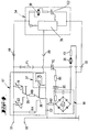
- the circuit is supplied via current connection points 32, 33, which power connection points 32, 33 in direct Connected to the power supply connections already mentioned 18, 19 formed as a suction nozzle 11 Device attachment 34.
- the power connection point 33 forms the neutral conductor, which is also directly above an excitation field coil F2 is connected to the blower motor 35 is.
- the power supply to the blower motor 35 takes place via a triac TC.
- This Triac TC is another one Excitation field coil F1 upstream of the motor.
- the Triac TC is controlled by a diac DC, with an ohmic between the triac TC and the diac DC Resistor R1 is interposed.
- the Diac DC the control voltage is via a soft start electronics SE supplied, which is in series with a power supply electronics ST, which in turn is connected stands with the power connection point forming the P-conductor 32.
- a soft start electronics SE supplied, which is in series with a power supply electronics ST, which in turn is connected stands with the power connection point forming the P-conductor 32.
- an ohmic resistor R2 connected in series.
- the neutral conductor connected capacitor C2 provided which between the ohmic resistor R2 and the power supply electronics ST attacks.
- the power supply electronics ST settles in detail from two independently adjustable setting potentiometers 5, 23, one between the two setting potentiometers 5, 23 switchable switch 29, an ohmic resistor R3 in series with this and one to the potentiometer-resistor combination parallel ohmic resistor R4 together.
- Switching the switch 36 to the ohmic resistance R4 causes a reduction in the performance of the Blower motor 35.
- the ohmic resistance R4 is like this designed that the blower motor 35 with a minimum output running.
- switch 36 becomes the setting potentiometer-resistance combination bridged by means of the ohmic resistor R4.
- a relay circuit 37 provided, which via the signal connection 20 is controlled by the attachment 34.
- the Device attachment 34 supplies an electric motor 38, which drives a brush roller 12 (see FIG. 2).
- This Electric motor 38 stands with an integrated circuit 39 in connection, in which also the impulses of Run in wheel sensor 31.
- the integrated circuit 39 a signal to the relay circuit via the signal connection 20 37, with which the switch 36 on the ohmic Resistor R4 switches. This has the consequence that at Standstill of the front attachment motor 38 and / or at Indicating the non-use of the vacuum cleaner 1 Standstill of the rollers 30 the performance of the electric motor 35 is reduced to a minimum value.
- the integrated circuit 39 also causes a shutdown the electric motor 38 of the attachment 34, by the control voltage of that assigned to the electric motor 38 Triacs TC2 is interrupted.
- This control line forms 4 the connection between the setting potentiometer 5 and the switch 29 on the device housing side. This allows between the device handle 3 and the device housing 2 one compact design of coupling and connector realized will.
- FIG. 5 Another embodiment of the electronic circuit is shown in Fig. 5. This is also done here Power supply to the blower motor 35 via a triac TC.
- the power connection points 32 and 33 are as in the Example described above in direct connection to Power supply connections 18 and 19 of a device attachment.
- an integrated circuit 40 is provided here.
- the reference number 41 is the power supply of the integrated circuit 40.
- the integrated circuit 40 includes several modules. This is a line voltage synchronization module 42, a soft start module 43, an ignition pulse module 44, a phase control controller 45, a comparator 46 and a logic module 47. External are also one Device 48 for presetting the minimum power of the blower motor 35, another device 49 for Presetting of the start-up time of the soft start and two setting potentiometers 5 and 23 are provided.
- the logic module 47 is used to register the last made adjustment potentiometer 5 or 23.
- the changeover between an active, e.g. setting potentiometer 5 and an inactive setting potentiometer, 23 is done by actuating the inactive setting potentiometer, 23, for example.
- the logic module 47 registers this actuation and switches internally to the active setting potentiometer. This is emblematic in Fig. 5 marked by a switch.
- the phase gating controller is operated via the logic module 47 45 according to the set Value of the setting potentiometer 5 or 23 controlled. In this leading edge controller 45 also run the information of the soft start module 43, the Minimum power device 48 and comparator 46 a. The data in the controller 45 are corresponding processed to generate appropriate ignition pulses via the Ignition pulse module 44 on the triac TC for control to send it out.
- the leading edge controller 45 When switching on the vacuum cleaner 1 affects Soft start module 43 the leading edge controller 45 such that the preset 5 via the potentiometer Performance value only after a time delay is achieved.
- the setting potentiometers 5, 23 and also every additional usable setting potentiometer are in arranged in a hierarchy, whereby when the Vacuum cleaner 1 always the potentiometer 5 active which is arranged on the handle 4 of the handle 3 is.
- the device attachment 34 Via the signal connection 20, the device attachment 34 starting, as in the first embodiment described, a signal act on the comparator 46.
- the latter is designed so that when the input signal is inactive the leading edge controller 45 accordingly the preset power value of the setting potentiometer 5 or 23 responds.
- the switches Leading edge controller 45 um to the preset Value of the minimum power device 48 which is one Reduction in the performance of the blower motor 35 to the Minimum performance takes place. This happens, for example, at a standstill the device, in particular the device attachment 34, where the standstill of the rollers 30 by means of Sensor 31 is displayed.
- a dirt sensor is provided, which is integrated with that provided there Circuit 39 is connected.
- the input signal can be from one in the header 34 arranged acceleration sensor 50 can be supplied.
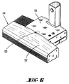
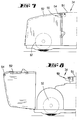
- the latter is in an area of the attachment 34 arranged in which a fixed housing cover 51 in a pivotable housing part 52 merges (see FIG. 6).
- the arrangement is such that the acceleration sensor 50 pivotable about an axis 53 mounted on the underside of the fixed housing cover 51 is, the acceleration sensor 50 over the Edge of the housing cover 51 and thus in the area of pivotable housing part 52 protrudes.
- the acceleration sensor 50 has a sensor shell 55 has, which is designed as a conical shell. Latter consists essentially of two halves 56 and 57 together, the shell half 56 a shell lower part and the shell half 57 is a shell top forms. Due to the cone-shaped design, the lower shell half 56 a deepest in its center Area B on.
- the sensor shell 55 has on the upper side a dome-like crest 58. The latter is on the top the upper shell half 57, for example glued.
- the tip 58 has bores for the passage the axis 53.
- the sensor shell 55 is thus in the Area of her crest 58 pivotable about the axis 53 in the housing near the fixed housing cover 51 of the device attachment 34 stored.
- the upper shell half 57 has one corresponding to the diameter of the light barrier 59 Breakthrough 60.
- the light barrier 59 thus acts in the Interior 61 of the sensor shell 55.
- a rolling body 62 is in shape a ball 63 freely movable.
- the acceleration sensor 50 or the sensor shell 55 is in the direction by means of a compression spring 64 about the axis 53 on the pin 54 of the pivotable housing part 52 biased.
- the electronic control device thus receives an active input signal, after which switching off the electric motor 38 of the attachment 34 and a decrease in the performance of the Blower motor 35 to a preset minimum power he follows.
- the device If the device is moved, it rolls Ball 63 due to the normal suction of Accelerations occurring from the carpeting deepest area B, the ball 63 also the Detection range of the light barrier 59 leaves. Of the Electric motor 38 is switched on without a delay time and increases the performance of the blower motor 35.
- the Sensor shell 55 is designed so that the accelerations sufficient to move the ball 63 in such a way to keep that the electric motor 38 is not turned off becomes.
- the ball 63 rolls when it is parked of the device, i.e. if not used if possible quickly in the middle, i.e. in the deepest area B back. This is a defined delay time guaranteed when switching off.
- the acceleration sensor is also a position sensor. Farther is due to the pivoting mounting of the Acceleration sensor 50 is a case opening sensor educated.
- FIG. 12-14 Another training example of an acceleration sensor 50 is shown in Figures 12-14.
- the acceleration sensor 50 has a circular shape Carrier plate 66, on the underside of which a cylinder-like Tube 67 is attached, for example by means of Weld.
- a dome-like summit 58 is provided, which is also connected to the carrier plate 66 is connected, for example, by welding. Also here the crest has 58 openings for passage the axis 53 fastened on the housing side.
- the one consisting of the soft spring 71 and the ball 72 Movement part 73 is in via the spring holder 68 integrated into a circuit.
- the spring holder has 68 a line connection 74.
- the tube 67 designed as a contact cylinder a line connection 75 integrated into this circuit.
- Swiveling also results in this exemplary embodiment of the housing part 52 for immediate switching on of the electric motor 38.
- the acceleration sensor 50 pivots according to the spring force of the compression spring 64 such that the ball 72 of the moving part 73 against the inner wall of tube 67 enters, making the circuit is closed.
- the acceleration sensor 50 also has here the function of a housing opening sensor.
- Acceleration sensor 50 by not inserting one conductive sleeve between the moving part 73 and the Deactivate tube 67. This can be done mechanically once the device is lifted out of the horizontal position or is pivoted. The circuit is then in consistently interrupted. The deactivation of the Acceleration sensor 50 or here the position sensor can also be triggered by opening the housing part 52 be.
Landscapes
- Engineering & Computer Science (AREA)
- Mechanical Engineering (AREA)
- Power Engineering (AREA)
- Electric Vacuum Cleaner (AREA)
- Nozzles For Electric Vacuum Cleaners (AREA)
- Filters For Electric Vacuum Cleaners (AREA)
- Control Of Electric Motors In General (AREA)
Description
- Fig. 1
- einen erfindungsgemäßen Staubsauger in Vorderansicht;
- Fig. 2
- den Staubsauger gemäß Fig. 1 in Seitenansicht;
- Fig. 3
- die Seitenansicht gemäß Fig. 2, jedoch bei abgenommenem Gerätestiel und umgesteckter Stromversorgung;
- Fig. 4
- eine Schaltungsanordnung zum zeitlich verzögerten Anlaufen eines Elektromotors des Staubsaugers, zum Voreinstellen des Leistungswertes über Einstellpotentiometer und zur Verminderung der Leistung des Elektromotors bei angezeigter Nichtbenutzung des Gerätes, eine erste Ausführungsform betreffend;
- Fig. 5
- ein Blockschaltbild, eine Schaltung gemäß Fig. 4 betreffend, jedoch in einer zweiten Ausführungsform;
- Fig. 6
- eine perspektivische Darstellung eines Gerätevorsatzes mit einem integrierten Beschleunigungssensor;
- Fig. 7
- den vorderen Endbereich des Gerätevorsatzes gemäß Fig. 6 in einer Seitenansicht;
- Fig. 8
- eine der Fig. 7 entsprechende Darstellung, jedoch nach Öffnen eines Gehäuseteiles;
- Fig. 9
- den Beschleunigungssensor in einer Einzeldarstellung, und zwar in Draufsicht;
- Fig. 10
- einen Schnitt durch den Beschleunigungssensor in eingebautem Zustand, bei geschlossenem Gehäuseteil gemäß Fig. 7;
- Fig. 11
- eine der Fig. 10 entsprechende Darstellung, jedoch nach Öffnen des Gehäuseteiles gemäß Fig. 8;
- Fig. 12
- eine der Fig. 9 entsprechende Darstellung, jedoch eine weitere Ausführungsform des Beschleunigungssensors betreffend;
- Fig. 13
- eine der Fig. 10 entsprechende Darstellung, den Beschleunigungssensor gemäß Fig. 12 betreffend; und
- Fig. 14
- eine der Fig. 11 entsprechende Darstellung, ebenfalls den Beschleunigungssensor gemäß 12 betreffend.
Claims (34)
- Staubsauger (1) mit einem hinsichtlich seiner Leistung steuerbaren Elektromotor (35), wobei an dem Staubsauger mehrere in gleicher Weise zur Leistungseinstellung des einen, die Saugleistung erbringenden Elektromotors (35) dienende Einstellpotentiometer (5, 23) ausgebildet sind, insbesondere an einem Staubsaugerstiel (3) und an einem Gerätegehäuse (2), dadurch gekennzeichnet, daß bei Aktivierung jeweils eines Einstellpotentiometers alle anderen Einstellpotentiometer selbsttätig oder durch Betätigung eines Umschalters (29) deaktiviert sind.
- Staubsauger nach Anspruch 1, dadurch gekennzeichnet, daß an dem Gerätegehäuse (3) zwei Einstellpotentiometer (23, 26) ausgebildet sind.
- Staubsauger nach einem oder mehreren der vorhergehenden Ansprüche, dadurch gekennzeichnet, daß die Einstellpotentiometer (5, 23, 26) in Kombination mit einem Handgriff (4, 22, 25) angeordnet sind.
- Staubsauger nach einem oder mehreren der vorhergehenden Ansprüche, dadurch gekennzeichnet, daß an dem Gerätegehäuse (2) eine Handgriff-Einstellpotentiometer-Kombination (24) an einer Gehäusebreitseite (21) ausgebildet ist.
- Staubsauger nach einem oder mehreren der vorhergehenden Ansprüche, dadurch gekennzeichnet, daß an dem Gerätegehäuse (2) eine Handgriff-Einstellpotentiometer-Kombination (27) an einer Gehäuseschmalseite (28) ausgebildet ist.
- Staubsauger nach einem oder mehreren der vorhergehenden Ansprüche, dadurch gekennzeichnet, daß die Umschaltung zwischen einem aktiven und einem inaktiven Einstellpotentiometer (5, 23, 26) durch Betätigung des inaktiven Einstellpotentiometers (5, 23, 26) erfolgt.
- Staubsauger nach einem oder mehreren der vorhergehenden Ansprüche, dadurch gekennzeichnet, daß die Umschaltung zwischen einem aktiven und einem inaktiven Einstellpotentiometer (5, 23, 26) durch einen zu betätigenden Umschalter (29) erfolgt.
- Staubsauger nach einem oder mehreren der vorhergehenden Ansprüche, dadurch gekennzeichnet, daß eine Umschaltung durch Abnahme des Gerätestieles (2) bewirkbar ist.
- Staubsauger nach einem oder mehreren der vorhergehenden Ansprüche, dadurch gekennzeichnet, daß bei Betätigung des Umschalters (29) eine Motorabstellung erfolgt.
- Staubsauger nach einem oder mehreren der vorhergehenden Ansprüche, dadurch gekennzeichnet, daß bei einer durch Stillstand des Gerätes (1) angezeigte Nichtbenutzung eine Verminderung der Leistung des Elektromotors (35) auf eine Minimalleistung erfolgt.
- Staubsauger nach einem oder mehreren der vorhergehenden Ansprüche, dadurch gekennzeichnet, daß die Verminderung der Leistung des Elektromotors (35) weiter in Abhängigkeit eines Signals eines Schmutzsensors erfolgt.
- Staubsauger nach einem oder mehreren der vorhergehenden Ansprüche, dadurch gekennzeichnet, daß die Nichtbenutzung durch eine Überwachung einer Laufrolle (30) des Gerätes (1) erfaßbar ist.
- Staubsauger nach einem oder mehreren der vorhergehenden Ansprüche, dadurch gekennzeichnet, daß bei Benutzung eines motorgetriebenen Vorsatzgerätes (34) eine angezeigte Nichtbenutzung eine Abschaltung des Elektromotors (38) des Vorsatzgerätes (34) bewirkt.
- Staubsauger nach einem oder mehreren der vorhergehenden Ansprüche, dadurch gekennzeichnet, daß die Nichtbenutzung durch einen Beschleunigungssensor (50) erfaßbar ist.
- Staubsauger nach einem oder mehreren der vorhergehenden Ansprüche, dadurch gekennzeichnet, daß in dem Beschleunigungssensor (50) ein Lagesensor integriert ist.
- Staubsauger nach einem oder mehreren der vorhergehenden Ansprüche, dadurch gekennzeichnet, daß der Beschleunigungssensor (50) bzw. der Lagesensor zugleich ein Gehäuse-Öffnungssensor ist.
- Staubsauger nach einem oder mehreren der vorhergehenden Ansprüche, dadurch gekennzeichnet, daß der Beschleunigungssensor (50) bzw. der Lagesensor durch eine Öffnung des Gerätes (34) deaktivierbar ist.
- Staubsauger nach einem oder mehreren der vorhergehenden Ansprüche, dadurch gekennzeichnet, daß der Beschleunigungssensor (50) zur Bildung des Gehäuse-Öffnungssensors schwenkbeweglich gelagert ist.
- Staubsauger nach einem oder mehreren der vorhergehenden Ansprüche, dadurch gekennzeichnet, daß der Beschleunigungssensor (50) in eine Schwenkstellung vorgespannt ist, welche Vorspannung durch Öffnung eines Gehäuseteiles (52) auslösbar ist.
- Staubsauger nach einem oder mehreren der vorhergehenden Ansprüche, dadurch gekennzeichnet, daß die Abschaltung zeitverzögert erfolgt.
- Staubsauger nach einem oder mehreren der vorhergehenden Ansprüche, dadurch gekennzeichnet, daß die Einschaltung des Elektromotors (38) praktisch ohne Verzögerung erfolgt.
- Staubsauger nach einem oder mehreren der vorhergehenden Ansprüche, dadurch gekennzeichnet, daß der Beschleunigungssensor (50) eine Sensor-Schale (55) aufweist, auf welcher ein Rollkörper (62) bewegbar ist und daß eine Lage des Rollkörpers (62) im tiefsten Bereich (B) der Schale (55) ein Abschalten des Elektromotors (38) bewirkt.
- Staubsauger nach einem oder mehreren der vorhergehenden Ansprüche, dadurch gekennzeichnet, daß der Rollkörper (62) eine Kugel (63) ist.
- Staubsauger nach einem oder mehreren der vorhergehenden Ansprüche, dadurch gekennzeichnet, daß die tiefste Lage der Kugel (63) über eine Lichtschranke (59) erfaßbar ist.
- Staubsauger nach einem oder mehreren der vorhergehenden Ansprüche, dadurch gekennzeichnet, daß die Schale (55) im wesentlichen rand- und oberseitig geschlossen ist.
- Staubsauger nach einem oder mehreren der vorhergehenden Ansprüche, dadurch gekennzeichnet, daß der Beschleunigungssensor (50) bzw. der Lagesensor als vertikal ausgerichtete Röhre (67) ausgebildet ist, mit einem darin pendelbeweglich gelagerten Bewegungsteil (73).
- Staubsauger nach einem oder mehreren der vorhergehenden Ansprüche, dadurch gekennzeichnet, daß das Bewegungsteil (73) klöppelartig aufgehängt ist.
- Staubsauger nach einem oder mehreren der vorhergehenden Ansprüche, dadurch gekennzeichnet, daß das Bewegungsteil (73) und die Röhre (67) jeweils elektrisch leitend sind.
- Staubsauger nach einem oder mehreren der vorhergehenden Ansprüche, dadurch gekennzeichnet, daß das Bewegungsteil (73) und die Röhre (67) in einem Stromkreis integriert sind, der durch Berührung der Teile (73) und (67) schließbar ist.
- Staubsauger nach einem oder mehreren der vorhergehenden Ansprüche, dadurch gekennzeichnet, daß der Beschleunigungssensor (50) durch Einschieben einer nicht leitenden Hülse zwischen dem Bewegungsteil (73) und der Röhre (67) deaktivierbar ist.
- Staubsauger nach einem oder mehreren der vorhergehenden Ansprüche, dadurch gekennzeichnet, daß die Deaktivierung durch Öffnen eines Gehäuseteiles (52) auslösbar ist.
- Staubsauger nach einem oder mehreren der vorhergehenden Ansprüche, dadurch gekennzeichnet, daß bei Benutzung eines motorgetriebenen Vorsatzgerätes (34) weiter die Überwachung durch eine Erfassung des Motorstromes des Elektromotors (38) des Vorsatzgerätes (34) erfolgt.
- Staubsauger nach einem oder mehreren der vorhergehenden Ansprüche, dadurch gekennzeichnet, daß bei einer Einschaltung des Staubsaugers (1) die Stromaufnahme des Elektromotors (35) derart einstellbar gesteuert ist, daß ein voreinstellbarer Leistungswert mit zeitlicher Verzögerung erreicht wird.
- Staubsauger nach einem oder mehreren der vorhergehenden Ansprüche, dadurch gekennzeichnet, daß die Einstellung der zeitlichen Verzögerung nur geräteintern durchführbar ist.
Priority Applications (2)
| Application Number | Priority Date | Filing Date | Title |
|---|---|---|---|
| SI9530134T SI0757537T1 (en) | 1994-04-27 | 1995-04-26 | Vacuum cleaner driven by an electric motor |
| EP97119530A EP0830832B1 (de) | 1994-04-27 | 1995-04-26 | Staubsauger mit einer Einrichtung zur Erkennung der Nichtbenutzung |
Applications Claiming Priority (5)
| Application Number | Priority Date | Filing Date | Title |
|---|---|---|---|
| DE4414695 | 1994-04-27 | ||
| DE4414695 | 1994-04-27 | ||
| DE4427639 | 1994-08-04 | ||
| DE4427639A DE4427639A1 (de) | 1993-12-04 | 1994-08-04 | Mittels eines Elektromotors betriebener Staubsauger |
| PCT/EP1995/001569 WO1995028867A1 (de) | 1994-04-27 | 1995-04-26 | Mittels eines elektromotors betriebener staubsauger |
Related Child Applications (1)
| Application Number | Title | Priority Date | Filing Date |
|---|---|---|---|
| EP97119530A Division EP0830832B1 (de) | 1994-04-27 | 1995-04-26 | Staubsauger mit einer Einrichtung zur Erkennung der Nichtbenutzung |
Publications (2)
| Publication Number | Publication Date |
|---|---|
| EP0757537A1 EP0757537A1 (de) | 1997-02-12 |
| EP0757537B1 true EP0757537B1 (de) | 1998-06-10 |
Family
ID=25935983
Family Applications (2)
| Application Number | Title | Priority Date | Filing Date |
|---|---|---|---|
| EP97119530A Expired - Lifetime EP0830832B1 (de) | 1994-04-27 | 1995-04-26 | Staubsauger mit einer Einrichtung zur Erkennung der Nichtbenutzung |
| EP95917960A Expired - Lifetime EP0757537B1 (de) | 1994-04-27 | 1995-04-26 | Mittels eines elektromotors betriebener staubsauger |
Family Applications Before (1)
| Application Number | Title | Priority Date | Filing Date |
|---|---|---|---|
| EP97119530A Expired - Lifetime EP0830832B1 (de) | 1994-04-27 | 1995-04-26 | Staubsauger mit einer Einrichtung zur Erkennung der Nichtbenutzung |
Country Status (8)
| Country | Link |
|---|---|
| EP (2) | EP0830832B1 (de) |
| AT (2) | ATE167034T1 (de) |
| AU (1) | AU2408095A (de) |
| DE (2) | DE59511100D1 (de) |
| DK (1) | DK0757537T3 (de) |
| ES (2) | ES2118597T3 (de) |
| SI (1) | SI0757537T1 (de) |
| WO (1) | WO1995028867A1 (de) |
Families Citing this family (8)
| Publication number | Priority date | Publication date | Assignee | Title |
|---|---|---|---|---|
| DE19608247A1 (de) * | 1996-03-04 | 1997-09-11 | Vorwerk Co Interholding | Staubsauger mit einem Motorgehäuse |
| DE10148513B4 (de) * | 2001-10-01 | 2013-06-27 | BSH Bosch und Siemens Hausgeräte GmbH | Vorrichtung zur Steuerung eines elektrischen Gerätes |
| ITBG20110025A1 (it) * | 2011-06-22 | 2012-12-23 | Tenacta Group Spa | "dispositivo aspirapolvere a spegnimento automatico" |
| GB2499240B (en) | 2012-02-10 | 2014-08-20 | Dyson Technology Ltd | Vacuum cleaner |
| CN111493739A (zh) * | 2020-05-27 | 2020-08-07 | 杭州欧备科技有限公司 | 一种基于灰尘感应继而实现转速调节的智能地刷 |
| CN113616122B (zh) * | 2021-05-27 | 2025-09-12 | 北京石头世纪科技股份有限公司 | 一种清洁设备及脏污检测方法 |
| KR20230112934A (ko) * | 2022-01-21 | 2023-07-28 | 엘지전자 주식회사 | 청소기 및 청소기의 제어방법 |
| CN114916882B (zh) * | 2022-05-31 | 2024-06-11 | 宁波博洋控股集团有限公司 | 洗地机的吸力调节方法 |
Family Cites Families (9)
| Publication number | Priority date | Publication date | Assignee | Title |
|---|---|---|---|---|
| NL7212108A (de) * | 1972-09-06 | 1974-03-08 | ||
| DE2644697A1 (de) * | 1976-10-02 | 1978-04-06 | Mauz & Pfeiffer Progress | Elektromotorisch angetriebenes geraet, insbesondere haushalt- und/oder gewerbe-staubsauger |
| DE2902161A1 (de) * | 1979-01-20 | 1980-07-24 | Miele & Cie | Staubsauger, insbesondere bodenstaubsauger |
| DE2923588A1 (de) * | 1979-06-11 | 1980-12-18 | Miele & Cie | Staubsauger, insbesondere bodenstaubsauger |
| SE456313B (sv) * | 1987-02-02 | 1988-09-26 | Electrolux Ab | Lasanordning, serskilt for en lucka till en dammsugare |
| JPS63246125A (ja) * | 1987-04-02 | 1988-10-13 | 松下電器産業株式会社 | 電気掃除機 |
| JP2674201B2 (ja) * | 1989-04-10 | 1997-11-12 | 松下電器産業株式会社 | 掃除機 |
| JP2983658B2 (ja) * | 1991-02-14 | 1999-11-29 | 三洋電機株式会社 | 電気掃除機 |
| DE9217416U1 (de) * | 1992-12-19 | 1993-04-08 | Fa. Fedag, Romanshorn | Reinigungswerkzeug mit angetriebener Bürstenwalze |
-
1995
- 1995-04-26 AT AT95917960T patent/ATE167034T1/de not_active IP Right Cessation
- 1995-04-26 DE DE59511100T patent/DE59511100D1/de not_active Expired - Fee Related
- 1995-04-26 EP EP97119530A patent/EP0830832B1/de not_active Expired - Lifetime
- 1995-04-26 AU AU24080/95A patent/AU2408095A/en not_active Abandoned
- 1995-04-26 DE DE59502519T patent/DE59502519D1/de not_active Expired - Fee Related
- 1995-04-26 SI SI9530134T patent/SI0757537T1/xx unknown
- 1995-04-26 AT AT97119530T patent/ATE418905T1/de not_active IP Right Cessation
- 1995-04-26 EP EP95917960A patent/EP0757537B1/de not_active Expired - Lifetime
- 1995-04-26 ES ES95917960T patent/ES2118597T3/es not_active Expired - Lifetime
- 1995-04-26 ES ES97119530T patent/ES2316156T3/es not_active Expired - Lifetime
- 1995-04-26 WO PCT/EP1995/001569 patent/WO1995028867A1/de not_active Ceased
- 1995-04-26 DK DK95917960T patent/DK0757537T3/da active
Also Published As
| Publication number | Publication date |
|---|---|
| DE59511100D1 (de) | 2009-02-12 |
| AU2408095A (en) | 1995-11-16 |
| EP0830832A3 (de) | 1998-09-16 |
| EP0757537A1 (de) | 1997-02-12 |
| ATE418905T1 (de) | 2009-01-15 |
| ATE167034T1 (de) | 1998-06-15 |
| EP0830832A2 (de) | 1998-03-25 |
| ES2316156T3 (es) | 2009-04-01 |
| EP0830832B1 (de) | 2008-12-31 |
| DE59502519D1 (de) | 1998-07-16 |
| DK0757537T3 (da) | 1999-03-29 |
| ES2118597T3 (es) | 1998-09-16 |
| SI0757537T1 (en) | 1998-12-31 |
| WO1995028867A1 (de) | 1995-11-02 |
Similar Documents
| Publication | Publication Date | Title |
|---|---|---|
| DE69936900T2 (de) | Rotationsbürstenanordnung und damit ausgerüsteter Staubsauger | |
| DE3855851T2 (de) | Elektrisches Reinigungsgerät | |
| EP0394641B1 (de) | Einstellvorrichtung für Bodenpflegegeräte | |
| DE69804253T2 (de) | Verbesserungen bei beweglichen robotern und bei ihren steuerungssystemen | |
| EP0630604B1 (de) | Bodensauggerät, insbesondere Vorsatz oder Teil eines Elektro-Staubsaugers | |
| DE4340771A1 (de) | Automatische Reinigungsvorrichtung | |
| DE102008004134B4 (de) | Verfahren zum Betreiben eines Elektrogeräts mit einem verbesserten Kabelwickelsystem | |
| EP0681445A1 (de) | Gerät zur bodenpflege | |
| EP0552652A1 (de) | Bodendüse für Staubsauger | |
| EP0830832B1 (de) | Staubsauger mit einer Einrichtung zur Erkennung der Nichtbenutzung | |
| DE69118102T2 (de) | Vorrichtung zum Anhalten der Trommel einer mantelbeschickbaren Trommelwaschmaschine in der Beschickungsposition | |
| DE3431164A1 (de) | Staubsauger | |
| AT397030B (de) | Antriebseinrichtung für bodenbearbeitungswerkzeuge von bodenpflegemaschinen | |
| EP1535765B1 (de) | Anhängerkupplung | |
| WO2013086551A1 (de) | Schalter | |
| DE69917355T2 (de) | Steuerungsvorrichtung eines Elektomotors, der ein Teil antreibt | |
| DE3236398C2 (de) | ||
| DE68905252T2 (de) | Mundstueck fuer staubsauger. | |
| WO2008009583A1 (de) | Elektro-staubsauger mit einem grundgerät und einem vorsatzgerät | |
| DE4427639A1 (de) | Mittels eines Elektromotors betriebener Staubsauger | |
| DE202020002176U1 (de) | Arbeitsmaschine | |
| EP0607612B1 (de) | Betriebsverfahren für eine Rohrreinigungsmaschine und Rohrreinigungsmaschine für die Durchführung des Betriebsverfahrens | |
| DE202018104549U1 (de) | Saugdüse für einen Staubsauger sowie Staubsauger zum Reinigen eines Bodenbelages | |
| WO2006069923A1 (de) | Verfahren zum erfassen der vor- und rückbewegung eines staubsaugers sowie staubsauger hierzu | |
| EP0951725B1 (de) | Endschaltervorrichtung |
Legal Events
| Date | Code | Title | Description |
|---|---|---|---|
| PUAI | Public reference made under article 153(3) epc to a published international application that has entered the european phase |
Free format text: ORIGINAL CODE: 0009012 |
|
| 17P | Request for examination filed |
Effective date: 19961021 |
|
| AK | Designated contracting states |
Kind code of ref document: A1 Designated state(s): AT BE CH DE DK ES FR GB GR IE IT LI LU MC NL PT SE |
|
| AX | Request for extension of the european patent |
Free format text: LT PAYMENT 961021;SI PAYMENT 961021 |
|
| GRAG | Despatch of communication of intention to grant |
Free format text: ORIGINAL CODE: EPIDOS AGRA |
|
| 17Q | First examination report despatched |
Effective date: 19970516 |
|
| GRAG | Despatch of communication of intention to grant |
Free format text: ORIGINAL CODE: EPIDOS AGRA |
|
| GRAH | Despatch of communication of intention to grant a patent |
Free format text: ORIGINAL CODE: EPIDOS IGRA |
|
| GRAH | Despatch of communication of intention to grant a patent |
Free format text: ORIGINAL CODE: EPIDOS IGRA |
|
| GRAA | (expected) grant |
Free format text: ORIGINAL CODE: 0009210 |
|
| AK | Designated contracting states |
Kind code of ref document: B1 Designated state(s): AT BE CH DE DK ES FR GB GR IE IT LI LU MC NL PT SE |
|
| AX | Request for extension of the european patent |
Free format text: LT PAYMENT 961021;SI PAYMENT 961021 |
|
| REF | Corresponds to: |
Ref document number: 167034 Country of ref document: AT Date of ref document: 19980615 Kind code of ref document: T |
|
| REG | Reference to a national code |
Ref country code: CH Ref legal event code: NV Representative=s name: R. A. EGLI & CO. PATENTANWAELTE Ref country code: CH Ref legal event code: EP |
|
| GBT | Gb: translation of ep patent filed (gb section 77(6)(a)/1977) |
Effective date: 19980611 |
|
| REF | Corresponds to: |
Ref document number: 59502519 Country of ref document: DE Date of ref document: 19980716 |
|
| ITF | It: translation for a ep patent filed | ||
| ET | Fr: translation filed | ||
| REG | Reference to a national code |
Ref country code: ES Ref legal event code: FG2A Ref document number: 2118597 Country of ref document: ES Kind code of ref document: T3 |
|
| REG | Reference to a national code |
Ref country code: IE Ref legal event code: FG4D Free format text: GERMAN |
|
| REG | Reference to a national code |
Ref country code: PT Ref legal event code: SC4A Free format text: AVAILABILITY OF NATIONAL TRANSLATION Effective date: 19980910 |
|
| REG | Reference to a national code |
Ref country code: DK Ref legal event code: T3 |
|
| PLBE | No opposition filed within time limit |
Free format text: ORIGINAL CODE: 0009261 |
|
| STAA | Information on the status of an ep patent application or granted ep patent |
Free format text: STATUS: NO OPPOSITION FILED WITHIN TIME LIMIT |
|
| 26N | No opposition filed | ||
| PG25 | Lapsed in a contracting state [announced via postgrant information from national office to epo] |
Ref country code: MC Free format text: LAPSE BECAUSE OF NON-PAYMENT OF DUE FEES Effective date: 19991031 |
|
| REG | Reference to a national code |
Ref country code: GB Ref legal event code: IF02 |
|
| PGFP | Annual fee paid to national office [announced via postgrant information from national office to epo] |
Ref country code: DK Payment date: 20020315 Year of fee payment: 8 |
|
| PGFP | Annual fee paid to national office [announced via postgrant information from national office to epo] |
Ref country code: LU Payment date: 20020318 Year of fee payment: 8 |
|
| PGFP | Annual fee paid to national office [announced via postgrant information from national office to epo] |
Ref country code: IE Payment date: 20020319 Year of fee payment: 8 Ref country code: CH Payment date: 20020319 Year of fee payment: 8 Ref country code: BE Payment date: 20020319 Year of fee payment: 8 |
|
| PGFP | Annual fee paid to national office [announced via postgrant information from national office to epo] |
Ref country code: GR Payment date: 20020426 Year of fee payment: 8 |
|
| PGFP | Annual fee paid to national office [announced via postgrant information from national office to epo] |
Ref country code: NL Payment date: 20030403 Year of fee payment: 9 |
|
| PGFP | Annual fee paid to national office [announced via postgrant information from national office to epo] |
Ref country code: SE Payment date: 20030404 Year of fee payment: 9 Ref country code: GB Payment date: 20030404 Year of fee payment: 9 |
|
| PGFP | Annual fee paid to national office [announced via postgrant information from national office to epo] |
Ref country code: PT Payment date: 20030414 Year of fee payment: 9 |
|
| PG25 | Lapsed in a contracting state [announced via postgrant information from national office to epo] |
Ref country code: LU Free format text: LAPSE BECAUSE OF NON-PAYMENT OF DUE FEES Effective date: 20030426 |
|
| PG25 | Lapsed in a contracting state [announced via postgrant information from national office to epo] |
Ref country code: IE Free format text: LAPSE BECAUSE OF NON-PAYMENT OF DUE FEES Effective date: 20030428 |
|
| PG25 | Lapsed in a contracting state [announced via postgrant information from national office to epo] |
Ref country code: LI Free format text: LAPSE BECAUSE OF NON-PAYMENT OF DUE FEES Effective date: 20030430 Ref country code: DK Free format text: LAPSE BECAUSE OF NON-PAYMENT OF DUE FEES Effective date: 20030430 Ref country code: CH Free format text: LAPSE BECAUSE OF NON-PAYMENT OF DUE FEES Effective date: 20030430 Ref country code: BE Free format text: LAPSE BECAUSE OF NON-PAYMENT OF DUE FEES Effective date: 20030430 |
|
| BERE | Be: lapsed |
Owner name: *VORWERK & CO. INTERHOLDING G.M.B.H. Effective date: 20030430 |
|
| PG25 | Lapsed in a contracting state [announced via postgrant information from national office to epo] |
Ref country code: GR Free format text: LAPSE BECAUSE OF NON-PAYMENT OF DUE FEES Effective date: 20031104 |
|
| REG | Reference to a national code |
Ref country code: CH Ref legal event code: PL |
|
| LTLA | Lt: lapse of european patent or patent extension |
Effective date: 20030426 |
|
| REG | Reference to a national code |
Ref country code: IE Ref legal event code: MM4A |
|
| PG25 | Lapsed in a contracting state [announced via postgrant information from national office to epo] |
Ref country code: GB Free format text: LAPSE BECAUSE OF NON-PAYMENT OF DUE FEES Effective date: 20040426 |
|
| PG25 | Lapsed in a contracting state [announced via postgrant information from national office to epo] |
Ref country code: SE Free format text: LAPSE BECAUSE OF NON-PAYMENT OF DUE FEES Effective date: 20040427 |
|
| REG | Reference to a national code |
Ref country code: DK Ref legal event code: EBP |
|
| PG25 | Lapsed in a contracting state [announced via postgrant information from national office to epo] |
Ref country code: PT Free format text: LAPSE BECAUSE OF NON-PAYMENT OF DUE FEES Effective date: 20041026 |
|
| PG25 | Lapsed in a contracting state [announced via postgrant information from national office to epo] |
Ref country code: NL Free format text: LAPSE BECAUSE OF NON-PAYMENT OF DUE FEES Effective date: 20041101 |
|
| EUG | Se: european patent has lapsed | ||
| GBPC | Gb: european patent ceased through non-payment of renewal fee |
Effective date: 20040426 |
|
| REG | Reference to a national code |
Ref country code: PT Ref legal event code: MM4A Free format text: LAPSE DUE TO NON-PAYMENT OF FEES Effective date: 20041026 |
|
| NLV4 | Nl: lapsed or anulled due to non-payment of the annual fee |
Effective date: 20041101 |
|
| PGFP | Annual fee paid to national office [announced via postgrant information from national office to epo] |
Ref country code: ES Payment date: 20090420 Year of fee payment: 15 |
|
| PGFP | Annual fee paid to national office [announced via postgrant information from national office to epo] |
Ref country code: IT Payment date: 20090429 Year of fee payment: 15 Ref country code: FR Payment date: 20090407 Year of fee payment: 15 Ref country code: DE Payment date: 20090408 Year of fee payment: 15 Ref country code: AT Payment date: 20090407 Year of fee payment: 15 |
|
| REG | Reference to a national code |
Ref country code: FR Ref legal event code: ST Effective date: 20101230 |
|
| PG25 | Lapsed in a contracting state [announced via postgrant information from national office to epo] |
Ref country code: AT Free format text: LAPSE BECAUSE OF NON-PAYMENT OF DUE FEES Effective date: 20100426 |
|
| PG25 | Lapsed in a contracting state [announced via postgrant information from national office to epo] |
Ref country code: DE Free format text: LAPSE BECAUSE OF NON-PAYMENT OF DUE FEES Effective date: 20101103 |
|
| PG25 | Lapsed in a contracting state [announced via postgrant information from national office to epo] |
Ref country code: IT Free format text: LAPSE BECAUSE OF NON-PAYMENT OF DUE FEES Effective date: 20100426 |
|
| REG | Reference to a national code |
Ref country code: ES Ref legal event code: FD2A Effective date: 20110715 |
|
| PG25 | Lapsed in a contracting state [announced via postgrant information from national office to epo] |
Ref country code: ES Free format text: LAPSE BECAUSE OF NON-PAYMENT OF DUE FEES Effective date: 20110705 |
|
| PG25 | Lapsed in a contracting state [announced via postgrant information from national office to epo] |
Ref country code: ES Free format text: LAPSE BECAUSE OF NON-PAYMENT OF DUE FEES Effective date: 20100427 |
|
| PG25 | Lapsed in a contracting state [announced via postgrant information from national office to epo] |
Ref country code: FR Free format text: LAPSE BECAUSE OF NON-PAYMENT OF DUE FEES Effective date: 20100430 |