EP0757415B1 - A joint terminal - Google Patents
A joint terminal Download PDFInfo
- Publication number
- EP0757415B1 EP0757415B1 EP96112379A EP96112379A EP0757415B1 EP 0757415 B1 EP0757415 B1 EP 0757415B1 EP 96112379 A EP96112379 A EP 96112379A EP 96112379 A EP96112379 A EP 96112379A EP 0757415 B1 EP0757415 B1 EP 0757415B1
- Authority
- EP
- European Patent Office
- Prior art keywords
- joint terminal
- contact parts
- connector housing
- contact
- locking
- Prior art date
- Legal status (The legal status is an assumption and is not a legal conclusion. Google has not performed a legal analysis and makes no representation as to the accuracy of the status listed.)
- Expired - Lifetime
Links
- 239000003381 stabilizer Substances 0.000 claims description 23
- 210000001503 joint Anatomy 0.000 claims description 2
- VRDIULHPQTYCLN-UHFFFAOYSA-N Prothionamide Chemical compound CCCC1=CC(C(N)=S)=CC=N1 VRDIULHPQTYCLN-UHFFFAOYSA-N 0.000 claims 1
- 238000000605 extraction Methods 0.000 description 12
- 238000003780 insertion Methods 0.000 description 9
- 230000037431 insertion Effects 0.000 description 9
- 238000009413 insulation Methods 0.000 description 8
- 238000005452 bending Methods 0.000 description 3
- 238000009434 installation Methods 0.000 description 3
- 230000014759 maintenance of location Effects 0.000 description 3
- 238000000034 method Methods 0.000 description 3
- 230000000087 stabilizing effect Effects 0.000 description 3
- 239000004020 conductor Substances 0.000 description 1
- 239000004615 ingredient Substances 0.000 description 1
- 239000000463 material Substances 0.000 description 1
- 239000002184 metal Substances 0.000 description 1
- 238000012986 modification Methods 0.000 description 1
- 230000004048 modification Effects 0.000 description 1
- 230000000149 penetrating effect Effects 0.000 description 1
- 230000002265 prevention Effects 0.000 description 1
- 230000001105 regulatory effect Effects 0.000 description 1
- 239000011347 resin Substances 0.000 description 1
- 229920005989 resin Polymers 0.000 description 1
- XLYOFNOQVPJJNP-UHFFFAOYSA-N water Substances O XLYOFNOQVPJJNP-UHFFFAOYSA-N 0.000 description 1
Images


Classifications
-
- H—ELECTRICITY
- H01—ELECTRIC ELEMENTS
- H01R—ELECTRICALLY-CONDUCTIVE CONNECTIONS; STRUCTURAL ASSOCIATIONS OF A PLURALITY OF MUTUALLY-INSULATED ELECTRICAL CONNECTING ELEMENTS; COUPLING DEVICES; CURRENT COLLECTORS
- H01R13/00—Details of coupling devices of the kinds covered by groups H01R12/70 or H01R24/00 - H01R33/00
- H01R13/02—Contact members
- H01R13/04—Pins or blades for co-operation with sockets
-
- H—ELECTRICITY
- H01—ELECTRIC ELEMENTS
- H01R—ELECTRICALLY-CONDUCTIVE CONNECTIONS; STRUCTURAL ASSOCIATIONS OF A PLURALITY OF MUTUALLY-INSULATED ELECTRICAL CONNECTING ELEMENTS; COUPLING DEVICES; CURRENT COLLECTORS
- H01R13/00—Details of coupling devices of the kinds covered by groups H01R12/70 or H01R24/00 - H01R33/00
- H01R13/40—Securing contact members in or to a base or case; Insulating of contact members
- H01R13/42—Securing in a demountable manner
- H01R13/436—Securing a plurality of contact members by one locking piece or operation
- H01R13/4361—Insertion of locking piece perpendicular to direction of contact insertion
-
- H—ELECTRICITY
- H01—ELECTRIC ELEMENTS
- H01R—ELECTRICALLY-CONDUCTIVE CONNECTIONS; STRUCTURAL ASSOCIATIONS OF A PLURALITY OF MUTUALLY-INSULATED ELECTRICAL CONNECTING ELEMENTS; COUPLING DEVICES; CURRENT COLLECTORS
- H01R31/00—Coupling parts supported only by co-operation with counterpart
- H01R31/08—Short-circuiting members for bridging contacts in a counterpart
-
- H—ELECTRICITY
- H01—ELECTRIC ELEMENTS
- H01R—ELECTRICALLY-CONDUCTIVE CONNECTIONS; STRUCTURAL ASSOCIATIONS OF A PLURALITY OF MUTUALLY-INSULATED ELECTRICAL CONNECTING ELEMENTS; COUPLING DEVICES; CURRENT COLLECTORS
- H01R13/00—Details of coupling devices of the kinds covered by groups H01R12/70 or H01R24/00 - H01R33/00
- H01R13/40—Securing contact members in or to a base or case; Insulating of contact members
- H01R13/42—Securing in a demountable manner
- H01R13/422—Securing in resilient one-piece base or case, e.g. by friction; One-piece base or case formed with resilient locking means
- H01R13/4223—Securing in resilient one-piece base or case, e.g. by friction; One-piece base or case formed with resilient locking means comprising integral flexible contact retaining fingers
Definitions
- This kind of joint terminal comprises a structure wherein a plurality of contact parts are connected with each other at the rear end part and accommodated in a connector housing.
- a plurality of opposite terminals contained in an opposite connector and connected with a plurality of wires are connected with each contact part of a joint terminal such that the wires are shorted electroconductively.
- a WIRE-TO-WIRE type connector housing represents a structure wherein cavities for accommodating terminals are divided off by separating walls designed to reach a rear end surface of a connector housing, contact parts connecting each other at the rear end portions thereof protrude in a bare state in the case where a joint terminal is introduced by inserting connecting parts into each cavity, resulting in the problem that electric insulation cannot be ensured.
- the published German patent DE-A-44 11 306 teaches a joint terminal being adapted to be introduced into a connector housing. It comprises a plurality of contact parts adapted to contact, at a front portion, opposite contact parts introduced into the connector housing and a connect part connected with each contact part at a rear portion. The rear portion is covered by an insulating layer.
- the preamble of claim 1 is based on this document.
- document EP-A-0 624 936 teaches a joint connector for connecting a plurality of wires having terminals holding the respective wires, and a connector housing.
- the connector housing includes terminal receiving chambers for receiving the respective terminals, and a retainer.
- the retainer is abutted against the terminals to retain the terminals in the respective predetermined positions, the retainer having a retainer body and a joint member mounted on the retainer body for electrically short-circuiting the terminals which are desired to connect together.
- the present invention starts out from the above-described circumstances. Its object is to provide a joint terminal capable of being installed in a state ensuring electric insulation for a WIRE-TO-WIRE type connector housing to establish connection between wires which are associated in a 1-to-1 relation.
- the present invention relates to a joint terminal for shorting a plurality of wires.
- each of the three contact parts 12S, 12C, 12S are connected with the connecting part 13, and the connecting part 13 and the rear edge portions of the three contact parts 12S, 12C, 12S are covered by the non-electroconductive molded layer 20.
- connecting part 13 protrudes out of the connector housing in its installed condition at the WIRE-TO-WIRE type connector housing, insulation is maintained because this connecting part 13 is covered by the non-electroconductive molded layer.
- Fig. 1 is a lateral view of the joint terminal in a first preferred embodiment of the present invention.
- Fig. 2 is a planar view of the joint terminal of Fig. 1.
- Fig. 3 is a side view of the joint terminal of Fig. 1.
- Fig. 4 is a lateral view of the connector housing wherein the joint terminal of Fig. 1 is to be installed.
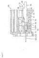
- Fig. 5 is a side view of the joint terminal of Fig. 1 when installed in the connector housing.
- the insulating layer comprises a first region covering said contact parts at the rear portion and being adapted to be introduced into cavities of said connector housing, thereby providing dustproofing for the cavities.
- the insulating layer comprises a second region arranged adjacent to the first region and being adapted to close said cavities, thereby providing dustproofing for the cavities. Furthermore, the insulating layer comprises a third region covering the connecting part and having a thickness which is smaller than the thickness of the second region, thereby facilitating handling of the joint terminal.
- At least one of the contact parts is provided with first locking means for locking the terminal joint within said connector housing.
- At least one of the contact parts is provided with a stabilizer facilitating insertion of the joint terminal into the connector housing.
- the first locking means and the stabilizer are positioned on the same side of the contact parts at the front portion.
- an odd number of contact parts is provided and a contact part located at a center position is provided with said first locking means.
- connector means comprise a connector housing and at least one joint terminal according to any of the preceding aspects of the present invention.
- connector means comprise second locking means for further locking said at least one joint terminal within the connector housing (30).
- a joint terminal comprises a plurality of contact parts capable of being contacted with an opposite terminal inserted in the connector housing in parallel, with the plurality of contact parts mutually connecting each other such as to be electroconductive at the outside of the conductor housing, and a non-electroconductive molded layer covering the plural number of contact parts.
- the contact parts protrude outwardly of the connector housing when installed in the WIRE-TO-WIRE type connector housing for mutually connecting wires associated in a 1-to-1 relation, but electric insulation is ensured because this contact part is covered with a non-electroconductive molded layer.
- the joint terminal can be installed in a state securing an electric insulation to a WIRE-TO-WIRE type connector housing for mutually connecting wires associated in a 1-to-1 relation.
- the joint terminal is provided at only one of the plurality of contact parts with a locking portion for locking it in a state inserted into the connector housing.
- the joint terminal when the single locking portion is locked, the whole joint connector can be in an installed state and when the single locking portion is unlocked, the joint terminal can be removed from the connector housing.
- insertion can be performed without problems.
- removal can be performed conveniently.
- the joint terminal comprises an odd number of contact parts and the locking portion is located at the center contact part.
- frictional resistance is generated at a position having a good balance in the direction arranging the contact parts when the locking portion contacted with the inner wall of the contact parts in accordance with the insertion and extraction of the joint terminal generates frictional resistance. Even though frictional resistance against insertion and extraction of the joint terminal is generated, there is no danger of the joint terminal inclining or jamming owing to the frictional resistance, so that the operation of insertion and extraction of the joint terminal can be performed smoothly.
- the joint terminal comprises stabilizers for stabilizing its orientation inside the connector housing at only those contact parts located on either side.
- the orientation of the joint terminal inside the connector housing is stabilized by the stabilizers of the contact parts located on either side.
- the distance between both of the stabilizers becomes wide and its orientation becomes fully stabilized as compared with the case of setting the contact parts other than at the sides.
- the joint terminal 10 of the present embodiment is constituted of the main body of the terminal 11 and the molded layer 20.
- the main body of the terminal 11 is formed by stamping an electrically conductive metal plate material in a prescribed shape and by executing bending and cutout processes.
- the main body of the terminal 11 is composed of three long and slender plate-type contact parts 12S, 12C and 12S extending in a forward direction in parallel with each other, and the plate-type connecting part 13 connecting these three contact parts 12S, 12C and 12S at their rear end portions to enable mutual electric conduction, whereby each of the contact parts 12S, 12C is contiguous with the connecting part.
- the locking portion 14 is provided to prevent unintended extraction of the joint terminal 10 while it is inserted into the connector housing 30 mentioned later.
- This locking portion 14 is formed by executing a cut-out process in the location of approximately one-third from the front edge of the contact part 12C, and the cut-out edge has a shape protruding in an oblique backward direction towards the lower side of the contact part. This locking portion 14 can be locked with the lance 33 of the connector housing 30 and the prevention of the extraction of the joint terminal 10 is provided by this hook.
- Two stabilizers 15, 15 for stabilizing the orientation of the joint terminal 10 inside the connector housing 30 are set at the two respective contact parts 12S, 12S located at both the right and the left sides of the three contact parts 12S, 12C, 12S.
- These stabilizers 15, 15 are formed by a process bending downward a square portion protruding from the outer side edge of the lateral edges of each contact part 12S and designed to be in contact with the side of the lance 33. Besides, the retainer 35 mounted on the connector housing 30 can be hooked on the rear edge portions of the stabilizers 15 to thereby prevent extraction of the joint terminal 10. Besides, the stabilizers 15 are only provided at two positions of the outer side edges of the two sides of the contact parts but not at the inner side edges of the two sides of the contact parts 12S and of the the center contact part 12C.
- the connecting part 13 is arranged so as to connect the rear edge portions of the three contact parts 12S, 12C, 12S among each other and to protrude in a rearward direction from the connector housing 30 in the condition where the joint terminal 10 is mounted on the connector housing 30.
- the retention holes 16, 16 are formed by stamping so as to form a passage between the top and bottom sides in the two locations, and the extraction of the molded layer 20 described later from the connecting part 13 is designed to be regulated by these retention holes 16.
- the molded layer 20 comprising a non-electroconductive resin ingredient is provided for the terminal main body 11 of this composition.
- This molded layer 20 covers approximately half of the range in a longitudinal direction from the rear end of the three contact parts 12S, 12C, 12S (the portion contiguous with the connecting part 13) and the entirety of the connecting part 13.
- a part of the molded layer 20 enters into the retention holes 16, whereby the molded layer 20 is strongly unified with the terminal main body 11.
- each contact part 12S, 12C, 12S covered with the molded layer 20 has a narrower shape than the range located in front of the above range and not covered with the molded layer 20, and both lateral edges of each contact part 12S, 12C, 12S are covered by the molded layer 20 having a thickness which corresponds to the difference in width between these two portions.
- the side 12A of the contact parts 12S, 12C, 12S of the range not covered with the molded layer 20 and that of the side 21 of the molded layer 20 which is backward from it have the same width dimension in smooth continuation.
- the thickness of the front edge portion 23 is comparatively thin in the range covering the contact parts 12S, 12C, 12S, and the thickness of the portion 24 which is backward from it becomes thicker.
- the thickness of the portion 25 covering the connecting part 13 moreover is smaller than that of the portion 24 covering the rear edge side of the contact parts 12S, 12C, 12S.
- the entire range of the contact parts 12S, 12C, 12S and the connecting part 13 has the same thickness.
- the portion 25 covering the connecting part 13 among the molded layer 20 becomes the gripping portion 26 suited to be grasped by the fingers of an operator for insertion and extraction of the joint terminal 10 against the connector housing 30.
- the difference in level is set at the boundary part wherein the thickness between the portion covering the contact part 12 and the gripping portion 26 in the upper side is different, and the finger-fitting side 27 is formed by this difference in level.
- the finger-hooking portion 28 furthermore is formed on the upper surface of the finger-fitting side 27 to be slightly higher than the portion covering contact parts 12 and slenderly extend to the right and left, and on the other hand, the finger-hooking portion 29 is formed under the lower surface to slenderly extend to the right and left in correspondence with the finger-hooking portion 28.
- a finger-tip can be hooked on the finger-hooking portions 28, 29 on either side for insertion and extraction of the joint terminal 10.
- the WIRE-TO-WIRE type for the mutual connection of wires associated in a 1-to-1 relation is used.
- a plurality of cavities 31 penetrating from the front end side to the rear end side are formed. These cavities 31 are separated from each other by the separating walls provided such as to reach the rear end of the connector housing 30, and the contact parts 12S, 12C, 12S of the joint terminal 10 are designed to be inserted in each cavity 31.
- the lance 33 capable of locking on the locking portion 14 if the joint terminal 10 is inserted into a regular position is provided.
- This lance 33 is able to be bent elastically and after the locking portion 14 is passed forward by bending the lance 38 downward during insertion of the contact parts 12S, 12C, 12S, the lance 33 is restored elastically and engages the rear end of the locking portion 14 designed to lock primarily the joint terminal 10 in this condition preventing extraction.
- the inner faces of the stabilizers 15 of the joint terminal are designed to be in contact with the side of this lance 33.
- the retainer 35 is designed to be fitted in from the retainer-installing hole 34 opened to the lower side.
- the retainer 35 is designed to be kept at two locations of a temporary locking position and a final locking position (the condition shown by figure 5).
- the contact parts 12S, 12C, 12S are permitted to be inserted into the cavity 31.
- the retainer 35 moves to the final locking position, the hooking part 36 of the retainer 35 is locked from the rear against the stabilizer 15 of the joint terminal 10 and therefore, the joint terminal 10 is locked secondarily in the condition preventing extraction.
- the joint terminal 10 When the joint terminal 10 is installed in the connector housing 30, the retainer 35 is maintained at the temporary locking position and the three contact parts 12S, 12C, 12S are inserted in the fixed cavity 31 from the rear of the connector housing 30 by grasping the gripping portion 26 with fingers. When the contact parts 12S, 12C, 12S are inserted into the regular position, the joint terminal 10 is locked primarily by the lance 33. When fingers are pushed against the finger-touching surface 27, an inserting manipulation becomes easy.
- the joint terminal 10 is locked secondarily by moving the retainer 35 to the final locking position and then a work installing the joint terminal 10 is completed.
- the separating wall 32 of the cavity 31 enters into the slits between the contact parts 12S, 12C, 12S in the condition that the joint terminal 10 was installed, and the rear end edge of the separating wall 32 abuts against the front end edge of the connecting part 13. Accordingly, the connecting part 13 takes a position in which it protrudes from the rear end side of the connector housing 30, but an electric insulation is maintained because the connecting part 13 is covered by the non-electroconductive molded layer 20.
- the molded layer 20 occupies almost entirely the opening part of the rear end side of the cavity 31. Hereby protection against entry of foreign matter into the cavity 31 and a simple water protection are achieved.
- the stabilizer 15 is contacted with the side of the lance 33 in the cavity 31.
- the orientation of the joint terminal 10 with respect to the connector housing 30 is kept uniformly in the horizontal plane (a plane parallel to the plate of the joint terminal 10).
- the front ends of the contact parts 12S, 12C, 12S protrude into the hood part 37 of the connector housing 30 and are contacted with the terminal of the opposite connector fitted with this hood part 37 in an electroconductive condition. According to this, the three terminals of the opposite side are shorted.
- the retainer 35 When the joint terminal 10 is removed from the connector housing 30, the retainer 35 first of all is transferred to the temporary locking position, a jig (not illustrated) is inserted from the opening of the front end side of the central cavity 31, engagement with the locking portion 14 is cancelled by pushing the lance 33 down, the joint terminal 10 is pulled backward while the locked condition is cancelled, the jig is pulled out after passing the locking portion 14 through the lance 33, and the joint terminal 10 may be drawn out to the rear.
- a jig (not illustrated) is inserted from the opening of the front end side of the central cavity 31, engagement with the locking portion 14 is cancelled by pushing the lance 33 down, the joint terminal 10 is pulled backward while the locked condition is cancelled, the jig is pulled out after passing the locking portion 14 through the lance 33, and the joint terminal 10 may be drawn out to the rear.
- the gripping portion 26 When the joint terminal 10 is drawn out to the rear, the gripping portion 26 is grasped with fingers; if the fingers seem to slip, pulling manipulation can be facilitated by engaging the finger-hooking portions 28, 29 with the finger-tips.
- the joint terminal 10 of the present embodiment has a configuration in which the connecting part 18 of the rear end is covered by the non-electroconductive molded layer 20, it can be installed in the condition keeping an electric insulation against the WIRE-TO-WIRE type connector housing 30 for mutually connecting wires associated in a 1-to-1 relation. Accordingly, it is unnecessary to prepare the exclusive connector housing 30 and a cost reduction can be achieved.
- the locking portion 14 for preventing extraction of the connector housing 30 is provided on only one connecting part 12C, resistance against insertion is small and the inserting operation is simplified. Furthermore, the operation of cancelling the engagement of the locking portion 14 and of the lance 33 is only one, and removing work is also easy.
- the locking portion 14 being the cause of the opposing force is provided at the contact part 12C occupying the central position among the three contact parts 12S, 12C, 12S.
- both stabilizers 15, 15 are provided only at the outer side edges of the two contact parts 12S, 12S located at both the right and left ends, the distance between both of the stabilizers 15, 15 is kept wide and a high functionality for stabilizing the posture is obtained, as compared with the case of providing the stabilizers 15 at the inner side edges of both of the contact parts 12S, 12S and of the central contact part 12C. Furthermore, as the number of stabilizers 15 is restricted to only two, the configuration becomes simple as compared with the case of providing three or more stabilizers 15, whereby a cost reduction can be achieved.
- a joint terminal wherein a connecting part connects each of three contact parts at a rear portion thereof.
- the connecting part and the rear portions of the contact parts are covered by a non-electroconductive molded layer, whereby insulation is maintained, although the connecting parts protrude out of a connector housing when installed with a WIRE-TO-WIRE type connector housing.
Landscapes
- Connector Housings Or Holding Contact Members (AREA)
- Coupling Device And Connection With Printed Circuit (AREA)
- Multi-Conductor Connections (AREA)
Applications Claiming Priority (3)
| Application Number | Priority Date | Filing Date | Title |
|---|---|---|---|
| JP21661795A JP3225801B2 (ja) | 1995-08-01 | 1995-08-01 | ジョイントターミナル |
| JP21661795 | 1995-08-01 | ||
| JP216617/95 | 1995-08-01 |
Publications (3)
| Publication Number | Publication Date |
|---|---|
| EP0757415A2 EP0757415A2 (en) | 1997-02-05 |
| EP0757415A3 EP0757415A3 (en) | 1998-01-07 |
| EP0757415B1 true EP0757415B1 (en) | 2000-03-22 |
Family
ID=16691245
Family Applications (1)
| Application Number | Title | Priority Date | Filing Date |
|---|---|---|---|
| EP96112379A Expired - Lifetime EP0757415B1 (en) | 1995-08-01 | 1996-07-31 | A joint terminal |
Country Status (5)
| Country | Link |
|---|---|
| US (1) | US5713759A (ja) |
| EP (1) | EP0757415B1 (ja) |
| JP (1) | JP3225801B2 (ja) |
| CN (1) | CN1096135C (ja) |
| DE (1) | DE69607261T2 (ja) |
Families Citing this family (10)
| Publication number | Priority date | Publication date | Assignee | Title |
|---|---|---|---|---|
| DE29605280U1 (de) * | 1996-03-21 | 1996-05-30 | Conrad Gerd | Querverbinder für Reihenklemmen |
| FR2766628B1 (fr) * | 1997-07-22 | 1999-10-22 | Entrelec Sa | Peigne d'interconnexion pour alignement de bornes de raccordement electrique d'un appareillage et module(s) de logement d'appareillage correspondant(s) |
| ES2199030B1 (es) * | 2001-09-07 | 2005-05-01 | Ge Power Controls Iberica, S.L. | Sistema de conexion electrica entre modulos para la proteccion de circuitos de distribucion electrica. |
| US6488520B1 (en) * | 2001-12-27 | 2002-12-03 | Fci Americas Technology, Inc. | Electrical connector assembly with shorting members |
| JP2008153103A (ja) | 2006-12-19 | 2008-07-03 | Sumitomo Wiring Syst Ltd | コネクタ |
| CN102035109B (zh) * | 2009-09-24 | 2014-11-05 | 日立金属株式会社 | 连接结构 |
| DE102010035704B4 (de) * | 2010-08-27 | 2012-08-30 | Wago Verwaltungsgesellschaft Mbh | Elektrischer Steckverbinder |
| DE202011104041U1 (de) * | 2011-08-04 | 2012-11-12 | Weidmüller Interface GmbH & Co. KG | Qerverbinder für eine Reihenanschlussklemme |
| JP2016207487A (ja) * | 2015-04-23 | 2016-12-08 | 株式会社オートネットワーク技術研究所 | ジョイントコネクタ |
| JP7255449B2 (ja) * | 2019-10-24 | 2023-04-11 | 株式会社オートネットワーク技術研究所 | ジョイントコネクタ |
Citations (1)
| Publication number | Priority date | Publication date | Assignee | Title |
|---|---|---|---|---|
| US5035654A (en) * | 1989-03-08 | 1991-07-30 | Japan Aviation Electronics Industry Limited | Electrical connector with socket contacts of different sizes having means for preventing erroneous connection |
Family Cites Families (9)
| Publication number | Priority date | Publication date | Assignee | Title |
|---|---|---|---|---|
| US3728656A (en) * | 1972-06-26 | 1973-04-17 | Gte Sylvania Inc | Transormer and terminal assembly |
| JPS61221107A (ja) * | 1985-03-28 | 1986-10-01 | Shiseido Co Ltd | 皮膚外用剤 |
| JP2685539B2 (ja) * | 1988-10-11 | 1997-12-03 | 株式会社大一商会 | 弾発遊技機 |
| JP2563707Y2 (ja) * | 1990-08-07 | 1998-02-25 | 矢崎総業株式会社 | コネクタ |
| DE69215134T2 (de) * | 1991-04-30 | 1997-03-06 | Yazaki Corp | Steckverbinder |
| JPH0545939A (ja) * | 1991-08-15 | 1993-02-26 | Mitsubishi Paper Mills Ltd | 電子写真平版印刷原版 |
| JP2594373Y2 (ja) * | 1993-01-14 | 1999-04-26 | 住友電装株式会社 | コネクタ |
| JPH06325842A (ja) * | 1993-05-14 | 1994-11-25 | Sumitomo Wiring Syst Ltd | ジョイントコネクタ |
| DE4411306C1 (de) * | 1994-03-31 | 1995-05-11 | Phoenix Contact Gmbh & Co | Elektrische Anschluß- und/oder Verbindungsklemme, insbesondere Reihenklemme, mit Steckbrücke sowie eine Steckbrücke |
-
1995
- 1995-08-01 JP JP21661795A patent/JP3225801B2/ja not_active Expired - Lifetime
-
1996
- 1996-07-29 CN CN96110854.1A patent/CN1096135C/zh not_active Expired - Fee Related
- 1996-07-31 EP EP96112379A patent/EP0757415B1/en not_active Expired - Lifetime
- 1996-07-31 DE DE69607261T patent/DE69607261T2/de not_active Expired - Lifetime
- 1996-08-01 US US08/691,115 patent/US5713759A/en not_active Expired - Lifetime
Patent Citations (1)
| Publication number | Priority date | Publication date | Assignee | Title |
|---|---|---|---|---|
| US5035654A (en) * | 1989-03-08 | 1991-07-30 | Japan Aviation Electronics Industry Limited | Electrical connector with socket contacts of different sizes having means for preventing erroneous connection |
Also Published As
| Publication number | Publication date |
|---|---|
| EP0757415A3 (en) | 1998-01-07 |
| EP0757415A2 (en) | 1997-02-05 |
| CN1147162A (zh) | 1997-04-09 |
| DE69607261T2 (de) | 2000-07-13 |
| JP3225801B2 (ja) | 2001-11-05 |
| DE69607261D1 (de) | 2000-04-27 |
| JPH0945440A (ja) | 1997-02-14 |
| CN1096135C (zh) | 2002-12-11 |
| US5713759A (en) | 1998-02-03 |
Similar Documents
| Publication | Publication Date | Title |
|---|---|---|
| JP2622938B2 (ja) | 端子位置保証部材付き電気コネクター | |
| US5252096A (en) | Connector | |
| US5647754A (en) | Short-circuit connector | |
| KR100501561B1 (ko) | 전기 터미널용 카울 커넥터 | |
| US5984705A (en) | Connector | |
| EP0386742B1 (en) | Electrical connector with socket contacts of different sizes having means for preventing erroneous connection | |
| EP1592091B1 (en) | An intermediate connector | |
| US7114997B2 (en) | Electrical connector | |
| EP0959532A1 (en) | A lever type connector | |
| EP0757415B1 (en) | A joint terminal | |
| US8033856B2 (en) | Electrical connector assembly | |
| JP7363626B2 (ja) | コネクタおよびコネクタ装置 | |
| EP0644617B1 (en) | Connector with terminal locking spacer | |
| US6129574A (en) | Connector having a construction for preventing an erroneous assembling of a connector housing and a cover | |
| EP0384591B1 (en) | Strain relief structure | |
| US4758183A (en) | Electrical connector with a wire cover | |
| US7393233B2 (en) | Electrical connector having locking mechanism for locking connector housings | |
| EP0397839B2 (en) | Electrical connector housing assembly | |
| JPS64791B2 (ja) | ||
| JP2547381Y2 (ja) | 多極コネクタ | |
| US20040102083A1 (en) | Receptacle connector with latch arms and plug connector to be connected thereto | |
| US6287153B1 (en) | Cable connector with improved engagement mechanism | |
| JPH0528698Y2 (ja) | ||
| EP0510229B1 (en) | An electrical connector with positive latch | |
| EP1439611B1 (en) | Connector for a ribbon cable |
Legal Events
| Date | Code | Title | Description |
|---|---|---|---|
| PUAI | Public reference made under article 153(3) epc to a published international application that has entered the european phase |
Free format text: ORIGINAL CODE: 0009012 |
|
| AK | Designated contracting states |
Kind code of ref document: A2 Designated state(s): DE FR GB |
|
| 17P | Request for examination filed |
Effective date: 19970228 |
|
| PUAL | Search report despatched |
Free format text: ORIGINAL CODE: 0009013 |
|
| AK | Designated contracting states |
Kind code of ref document: A3 Designated state(s): DE FR GB |
|
| 17Q | First examination report despatched |
Effective date: 19981215 |
|
| GRAG | Despatch of communication of intention to grant |
Free format text: ORIGINAL CODE: EPIDOS AGRA |
|
| GRAG | Despatch of communication of intention to grant |
Free format text: ORIGINAL CODE: EPIDOS AGRA |
|
| GRAH | Despatch of communication of intention to grant a patent |
Free format text: ORIGINAL CODE: EPIDOS IGRA |
|
| GRAH | Despatch of communication of intention to grant a patent |
Free format text: ORIGINAL CODE: EPIDOS IGRA |
|
| GRAA | (expected) grant |
Free format text: ORIGINAL CODE: 0009210 |
|
| AK | Designated contracting states |
Kind code of ref document: B1 Designated state(s): DE FR GB |
|
| PG25 | Lapsed in a contracting state [announced via postgrant information from national office to epo] |
Ref country code: FR Free format text: LAPSE BECAUSE OF FAILURE TO SUBMIT A TRANSLATION OF THE DESCRIPTION OR TO PAY THE FEE WITHIN THE PRESCRIBED TIME-LIMIT Effective date: 20000322 |
|
| REF | Corresponds to: |
Ref document number: 69607261 Country of ref document: DE Date of ref document: 20000427 |
|
| EN | Fr: translation not filed | ||
| PLBE | No opposition filed within time limit |
Free format text: ORIGINAL CODE: 0009261 |
|
| STAA | Information on the status of an ep patent application or granted ep patent |
Free format text: STATUS: NO OPPOSITION FILED WITHIN TIME LIMIT |
|
| 26N | No opposition filed | ||
| REG | Reference to a national code |
Ref country code: GB Ref legal event code: IF02 |
|
| PGFP | Annual fee paid to national office [announced via postgrant information from national office to epo] |
Ref country code: GB Payment date: 20040728 Year of fee payment: 9 |
|
| PG25 | Lapsed in a contracting state [announced via postgrant information from national office to epo] |
Ref country code: GB Free format text: LAPSE BECAUSE OF NON-PAYMENT OF DUE FEES Effective date: 20050731 |
|
| GBPC | Gb: european patent ceased through non-payment of renewal fee |
Effective date: 20050731 |
|
| PGFP | Annual fee paid to national office [announced via postgrant information from national office to epo] |
Ref country code: DE Payment date: 20130724 Year of fee payment: 18 |
|
| REG | Reference to a national code |
Ref country code: DE Ref legal event code: R119 Ref document number: 69607261 Country of ref document: DE |
|
| PG25 | Lapsed in a contracting state [announced via postgrant information from national office to epo] |
Ref country code: DE Free format text: LAPSE BECAUSE OF NON-PAYMENT OF DUE FEES Effective date: 20150203 |
|
| REG | Reference to a national code |
Ref country code: DE Ref legal event code: R119 Ref document number: 69607261 Country of ref document: DE Effective date: 20150203 |