EP0755787B1 - Vorrichtung zum Reinigen von Arbeitsflächen einer Druckmaschine, insbesondere Gummituchwaschanlage - Google Patents
Vorrichtung zum Reinigen von Arbeitsflächen einer Druckmaschine, insbesondere Gummituchwaschanlage Download PDFInfo
- Publication number
- EP0755787B1 EP0755787B1 EP96109454A EP96109454A EP0755787B1 EP 0755787 B1 EP0755787 B1 EP 0755787B1 EP 96109454 A EP96109454 A EP 96109454A EP 96109454 A EP96109454 A EP 96109454A EP 0755787 B1 EP0755787 B1 EP 0755787B1
- Authority
- EP
- European Patent Office
- Prior art keywords
- washing
- central computer
- transmission channel
- program
- control module
- Prior art date
- Legal status (The legal status is an assumption and is not a legal conclusion. Google has not performed a legal analysis and makes no representation as to the accuracy of the status listed.)
- Expired - Lifetime
Links
- 238000005406 washing Methods 0.000 title claims description 60
- 238000007639 printing Methods 0.000 title claims description 19
- 238000004140 cleaning Methods 0.000 title claims description 18
- 238000004891 communication Methods 0.000 claims description 75
- 230000005540 biological transmission Effects 0.000 claims description 43
- 238000004092 self-diagnosis Methods 0.000 claims description 7
- 239000012459 cleaning agent Substances 0.000 claims description 5
- 238000001514 detection method Methods 0.000 claims description 4
- 238000012544 monitoring process Methods 0.000 claims description 2
- 239000003795 chemical substances by application Substances 0.000 claims 4
- 239000003599 detergent Substances 0.000 description 12
- 239000007788 liquid Substances 0.000 description 10
- 238000012546 transfer Methods 0.000 description 8
- 239000004744 fabric Substances 0.000 description 6
- 239000012530 fluid Substances 0.000 description 5
- 230000006978 adaptation Effects 0.000 description 4
- 238000010586 diagram Methods 0.000 description 4
- 238000001035 drying Methods 0.000 description 4
- 230000006870 function Effects 0.000 description 4
- 238000013024 troubleshooting Methods 0.000 description 4
- 238000013475 authorization Methods 0.000 description 3
- 230000008901 benefit Effects 0.000 description 3
- 238000012423 maintenance Methods 0.000 description 3
- 230000007257 malfunction Effects 0.000 description 3
- 230000001105 regulatory effect Effects 0.000 description 3
- 238000012549 training Methods 0.000 description 3
- 238000004519 manufacturing process Methods 0.000 description 2
- 238000000034 method Methods 0.000 description 2
- 230000008569 process Effects 0.000 description 2
- 230000004044 response Effects 0.000 description 2
- 238000009420 retrofitting Methods 0.000 description 2
- 230000009471 action Effects 0.000 description 1
- 230000003213 activating effect Effects 0.000 description 1
- 230000004913 activation Effects 0.000 description 1
- 230000006399 behavior Effects 0.000 description 1
- 230000009286 beneficial effect Effects 0.000 description 1
- 238000010276 construction Methods 0.000 description 1
- 238000011109 contamination Methods 0.000 description 1
- 230000001276 controlling effect Effects 0.000 description 1
- 230000008878 coupling Effects 0.000 description 1
- 238000010168 coupling process Methods 0.000 description 1
- 238000005859 coupling reaction Methods 0.000 description 1
- 230000006735 deficit Effects 0.000 description 1
- 238000003745 diagnosis Methods 0.000 description 1
- 239000000835 fiber Substances 0.000 description 1
- 238000009434 installation Methods 0.000 description 1
- 238000012545 processing Methods 0.000 description 1
- 238000005086 pumping Methods 0.000 description 1
- 238000010992 reflux Methods 0.000 description 1
- 238000003860 storage Methods 0.000 description 1
Images


Classifications
-
- B—PERFORMING OPERATIONS; TRANSPORTING
- B41—PRINTING; LINING MACHINES; TYPEWRITERS; STAMPS
- B41F—PRINTING MACHINES OR PRESSES
- B41F35/00—Cleaning arrangements or devices
-
- B—PERFORMING OPERATIONS; TRANSPORTING
- B41—PRINTING; LINING MACHINES; TYPEWRITERS; STAMPS
- B41P—INDEXING SCHEME RELATING TO PRINTING, LINING MACHINES, TYPEWRITERS, AND TO STAMPS
- B41P2235/00—Cleaning
- B41P2235/10—Cleaning characterised by the methods or devices
- B41P2235/26—Spraying devices
Definitions
- the invention relates to a device for cleaning Work surfaces of a printing press, especially one Blanket washer.
- washing units designed as washing bars Actuators, such as controllable valves for a dispenser Cleaning fluid, and sensors on
- Actuators and sensors of one washing unit each for example 25-pin connection on one Central computer for the entire, all car washes and a pump station associated therewith Blanket washer are connected.
- the Central computer has one for each washing unit Druckmaschine a transfer element, whose task in essentially in an adapter function from the 25-pin, cables coming from the washing units to an internal ribbon cable system used in the central computer consists.
- the transfer elements are each to an as Programmable control trained sub control connected, which for required work processes holds parameterizable sequences in a memory, such as for performing a Washing process starting a washing and Drying cloth to a blanket cylinder to be cleaned, opening valves to dispense one Cleaning liquid for moistening the washing and Dry cloth, the further transport of the washing and Dry cloth and after the cleaning process closing the valves.
- the understeers are each via serial data lines with the Central computer of the blanket washing system connected. The The central computer takes inputs from operating personnel opposes and is the individual understeering parent.
- EP 0 654 350 A1 shows a device for fully automatic cylinder cleaning for printing machines, being used to control the washing processes as an extension of the central printing press control system Central computer should be provided. Here too no separate ones within the individual washing units Intelligence more present.
- EP 0 158 797 A2 shows a for presetting Provided actuators of a printing press Data transmission system that works like a fieldbus contains established transmission channels over which Signals can be sent and received.
- This device according to the invention is very inexpensive because of the wiring effort due to the Training with a common transmission channel for All washing units or the central computer assigned Communication modules is reduced and also the Components are very easy to assemble. Also reduced the installation effort considerably because none own under-controls assigned to the central computer for the washing units of one printing unit each required are. In addition, the number of required components significantly. Furthermore increased the device according to the invention the overall security of the Printing press in which it can be installed, clearly because unforeseen behavior in the structure according to the invention of wash bars in the event of communication problems is avoidable and the total amount of detergent is simple and can be precisely monitored and metered centrally. Is too retrofitting for additional printing units and / or wash bars quickly and easily low cost feasible.
- Each washing unit is preferably one Communication module assigned what compared to the Assignment of a communication module to all Washing units of a printing unit have the advantage of more modular Construction and faster troubleshooting.
- a communication module is expedient in each case Wash unit installed, so that during assembly on site this washing unit only to the Transmission channel must be connected.
- Macros are preferably via the transmission channel transferable what compared to the transfer of Individual signals for controlling actuators or for Reading from sensors the advantage of lower Bus utilization and thus higher reliability and Susceptibility to interference. It expediently includes a macro at least one header with a specific, communication module of a washing unit to be addressed or the identifier assigned to the central computer and a from this communication module as request, command or Response interpretable data sequence what a enables reliable and compressed transmission.
- a CAN fieldbus protocol can be used in the communication modules be implemented because this is in Non-generic applications are already reliable has proven.
- the access authorization of the communication modules to the Transmission channel is preferably through for that individual communication modules definable, each in priorities that can be stored are regulated, which is a enables fast arbitration.
- Appropriately includes a transmission access of a communication module to the Transmission channel as a start sequence Priority sequence in the event of a collision with priority sequences sent simultaneously by others Communication modules of lower priority on the Transmission channel dominated over these. This can for example in the form of an open collector solution be executed.
- a danger signal to be sent is expediently one priority over all other priorities assigned so that a quickly and reliably danger occurring via the transmission channel is communicable. This can be a specific Dangerous situation in all communication modules same priority or one in each communication module other high order priority can be assigned.
- Central computer a blanket washer central computer provided that without adaptation to a control center etc. can be connectable.
- the invention is a printing press control computer as Central computer provided, which is a very beneficial Training of the device, in particular Blanket washer control, in an overall control center concept allowed.
- the control module is preferably a wash bar from the central computer by transmitting Program data via the transmission channel to Control module of the wash bar programmable, what in extremely fast and reliable Adaptation to print jobs from the central computer, especially allowed from the control center. It is useful the local action program to control actuators, Reading out sensors and processing of Program steps in a control module from Control center out by communicating changes Part program can be modified at the control center.
- Modifiability of the local can also be advantageous Communication program in the communication module of a Washbar from the central computer to one Reconfiguration of the communication parameters from Central computer to enable.
- a washing bar is preferably in the control module a local control program for local Readjustment depending on by sensors measuring data provided in order to be without burdens of Transmission channel and the central computer one to ensure consistently reliable function.
- compensation of Contamination for example in the valves or from mechanical manufacturing tolerances, for example Nozzle diameter or the pressure applied to the nozzles done locally.
- a wash bar target amount of detergent to be dispensed by one Detergent quantity regulation sub-program in Central computer can be determined and that of a sensor in the Wash bar measured actual amount of detergent from one Detergent quantity detection subroutine in the central computer can be queried, which is a central specification of the target cleaning agent quantities and actually capturing the dispensed actual detergent quantities allowed.
- An addition program in the Central computer from the individual washing units dispensed detergent quantities the total Predictable amount of detergent.
- the communication modules in the washing units are preferably encapsulated to prevent impairment from the front Dampness and cleaning agents avoid.
- Figure 1 shows the already known structure of the mechanical components of a wash bar 1, the one fed from a supply roll 2 and after use recordable on a take-up roll 3, e.g. made of fleece existing washing and drying cloth 4, the over an elastic pressure bar 5 on the Flank of the wash bar on the blanket cylinder side 1 is led.
- the pressure bar 5 can be used to clean a Blanket cylinder 6, as in Figure 1 by interrupted Lines are indicated in and out of contact with this to be brought.
- the washing and drying towel 4 is over on a nozzle bar 7 arranged nozzles 8 with a Cleaning fluid for cleaning the blanket cylinder 6 acted upon, to provide a high Pressure at the nozzles 8 in the wash bar 1
- Integrated pressure booster 9 is provided.
- the pressure booster 9 is a Liquid line 11 with cleaning liquid and by means of a compressed air line 12 with compressed air as Operating resources can be supplied, the compressed air line 12 on a pressure surge generating device 16 and the Compressed air line 12 via a coupling device 13 a liquid pump 15 is connected.
- the High pressure line 10, and the Liquid line 11 and other lines such as for example the feed line of the liquid pump or the pressure surge generating device can by here Not shown, electronically controllable valves be lockable.
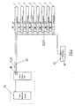
- FIG. 3 shows a block diagram of each other communicating components.
- a control module 17 in particular for the control of actuators 24 and sensors 23 and the storage of Sequences and a communication module 18 are provided.
- Communication modules 18 are provided at the pump station 15 and at the central computer 19 Communication modules 18 are provided. All communication modules are with a common transmission channel 20 connected, here the transmission channel 20 as Fieldbus and the communication modules as fieldbus nodes or fieldbus master card of a fieldbus system are.
- the fieldbus master card is here in the Central computer 19 is provided, which as a blanket washing central computer is formed, with an integrated concept is also the blanket control computer can be used as a central computer 19.
- the communication modules 18 implemented a CAN fieldbus protocol.
- each communication module 18 With the communication system shown can of each communication module 18 both sent signals as well as being received. So it is possible from Central computer 19 via its communication module 18, the Transmission channel 20 and the communication module 18 one any washbar targeted data on them To send wash bars and vice versa data like Sensor data, dangers or error messages from everyone Wash bar 1 from via its communication module 18 and the transmission channel 20 to the central computer 19 to send its communication module 18.
- the access authorization of the communication modules 18 the transmission channel 20 is in the example shown assigned by the individual communication modules priorities stored in a memory are regulated, the priorities of the communication modules 18 of the Washbar 1 and the priority of the communication module 18 of the pumping station 15 are arbitrarily selected relative to one another are and the communication module 18 of the central computer 19, i.e. the fieldbus mastercard, one for everyone Wash bar 1 and the liquid pump 15 higher Priority is assigned.
- the top priority is here Hazard reports assigned, these being the highest Priority from each participant, especially from the Wash bar 1, regardless of its individual Priority can be used. It can be used to avoid dangers like for example, disturbances in the supply of Cleaning fluid or pressure surges or at the Valve control reported immediately and the appropriate measures are taken.
- a communication module 18 When a communication module 18 tries to send data over the Send transmission channel 20, it occupies this here first with its priority identifier, the simultaneous registration of several communication modules 18 on the transmission channel 20 causes the highest priority sequence on the transmission channel 20 enforces what of all communication modules 18 is recognized, so that only that Communication module 18 that deals with its highest Has enforced priority on transmission channel 20 will send.
- the priority sequence of a Communication module 18, for example, logical "O" - and "1" signals include, when there is a collision a "1" signal with an "O" signal from another Communication module 18 lower priority a "1" signal on the fieldbus trained here Transmission channel 20 results. For example be implemented using an open collector solution.
- a communication module 18 due to its priority can start sending data.
- These can be constructed as macros, with a macro here at least one header with a specific one communication module of a washing unit to be addressed or the central computer 19 assigned identifier and a from the communication module 18 to be addressed as an inquiry, Command or response interpretable data sequence includes.
- a macro of the central computer 19 can a wash bar 1 are sent, whereupon Control module 17 a prefabricated and in one Processed memory stored program, so for example a wash bar 1 on the assigned Blanket cylinder 6 turns on, corresponding valves opens and the washing and drying cloth 4 with a Cleaning liquid applied, the corresponding Valves or pump or pressure surge generating device deactivated again and the pressure bar 5 of the Turns the wash bar off the blanket cylinder 6.
- the central computer can also be sent to everyone Washbar a common macro informing a request send over cleaning liquid used so far, whereupon the wash bars, because of their different priorities one after the other Central computer 19 with the one previously used Answer the data record that indicates the amount of detergent.
- the central computer can thus use an addition program from the reported, from the individual Wash units 1 dispensed quantities of detergent calculate the total amount of detergent used so far and determine if they already have one regarding Danger of fire in the dryer of the printing machine Value exceeds.
- the modular concept of the device according to the invention allowed when starting up, i.e. activating the system and during operation at different levels Functional checks.
- Control module 17 cause the wash bar into one to transfer stable state, in which for example all that enable the supply of cleaning agents Valves are closed. Is also an ongoing Self-diagnosis of actuators 24 and sensors 23 or Plausibility check of sensor messages by a Control module 17 of a wash bar 1 possible, in In the event of errors occurring over the transmission channel 20 a danger message with possibly high Priority or an error message can be sent.
- the central computer 19 via the Transmission channel 20 at any time a reconfiguration of the Washing programs in the washing bar 1 possible, so completely an effortless adaptation to that on the printing press Production to be made especially with regard to Wash intervals based on the paper amount of detergent used from the central computer to allow.
- the modular structure with local, independent systems in the washbar 1 also one much easier troubleshooting and maintenance because so Errors can be localized much faster.
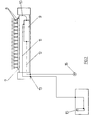
- FIG 4 shows the structure of the block diagram electronic components of a wash bar 1.
- the Communication takes place via a to the transmission channel 20 connected communication module 18, which does not have shown lines, in particular data lines with the Control module 17 is connected.
- Communication module 18 can Communication module 18 and the control module 17 also be realized on a circuit board.
- the two modules 17, 18 are connected to a common power supply a supply voltage connection 21 and a Ground connection 22 connected.
- the power supply is also indicated in Figure 3, the concrete Execution not necessarily the one shown Connection between two washbars required but also, for example, all wash bars Central power supply or on busbars etc. can be connected.
- Figure 4 also shows schematically several sensors 23, for example as Flow meter the dispensed Measure the amount of cleaning fluid or the like can and several actuators 24, such as shown here designed as controllable valves 24 through which the inflow of Cleaning fluid or pressure surges can be regulated can.
- the sensors 23 and actuators 24 are here one common ground line 25 out.
- the actuators 24 are each from the control module 17 after a in this stored sequence to be processed, e.g. on an activation command from the central computer 19 or after a certain period of time in a timer activated in the control module 17.
- the invention is not based on that described and illustrated embodiment limited. In particular it is also mechanically different Wash bars or with other transmission channels, such as for example, coaxial or fiber optic networks appropriate adaptation can be used.
Landscapes
- Inking, Control Or Cleaning Of Printing Machines (AREA)
Description
- Figur 1
- einen Schnitt durch einen Waschbalken einer einem Gummituchzylinder zugeordneten Gummituchwaschvorrichtung,
- Figur 2
- eine schematische Darstellung des Waschbalkens in Figur 1 und der ihm zugeordneten Flüssigkeitspumpe und Druckstoßerzeugungseinrichtung,
- Figur 3
- ein Blockschaltbild einer erfindungsgemäßen Gummituchwaschanlage mit mit einer Zentraleinheit über einen gemeinsamen Übertragungskanal kommunizierenden Waschbalken,
- Figur 4
- ein Blockschaltbild der elektronischen Komponenten eines Waschbalkens.
Claims (11)
- Vorrichtung zum Reinigen von Arbeitsflächen einer Druckmaschine, insbesondere Gummituchwaschanlage, mit mehreren mit einem Zentralrechner (19) verbundenen, jeweils Aktoren (24) und Sensoren (23) aufweisenden, vorzugsweise als Waschbalken ausgebildeten Wascheinheiten (1), wobei dem Zentralrechner (19) und jeder jeweils mindestens eine Wascheinheit (1) enthaltenden Teilmenge von Wascheinheiten (1) jeweils ein zumindest wascheinheitsnah angeordnetes Kommunikationsmodul (18) zugeordnet ist, wobei alle Kommunikationsmodule (18) mit einem Übertragungskanal (20) verbunden sind, über den Signale absendbar und empfangbar sind, und wobei mit den wascheinheitsnahen Kommunikationsmodulen (18) jeweils ein lokales Steuerungsmodul (17) verbunden ist, durch das die Aktoren (24) schaltbar, die Sensoren (23) auslesbar sowie Ablaufsequenzen speicherbar und ausführbar sind.
- Vorrichtung nach Anspruch 1, dadurch gekennzeichnet, daß jeder Wascheinheit (1) ein in sie eingebautes und/oder gekapseltes Kommunikationsmodul (18) zugeordnet ist.
- Vorrichtung nach einem der vorhergehenden Ansprüche, dadurch gekennzeichnet, daß der Übertragungskanal (20) als Feldbus und die Kommunikationsmodule (18) als Feldbusknoten eines Feldbus-Systems mit einem CAN(Controller Area Network)-Feldbusprotokoll, ausgebildet sind.
- Vorrichtung nach einem der vorhergehenden Ansprüche, dadurch gekennzeichnet, daß alle an den Übertragungskanal (20) angeschlossenen Teilnehmer (1,15,10) zumindest durch das dem Zentralrechner (19) zugeordnete Kommunikationsmodul (18) von einem Detektionsteilprogramm im Zentralrechner detektierbar sind.
- Vorrichtung nach einem der vorhergehenden Ansprüche, dadurch gekennzeichnet, daß über das die Kommunikationsmodule (18) und den Übertragungskanal (20) umfassende Bussystem zumindest beim Hochfahren eine automatische Selbstdiagnose von einem Selbstdiagnoseprogramm im Zentralrechner (19) durchführbar ist.
- Vorrichtung nach einem der vorhergehenden Ansprüche, dadurch gekennzeichnet, daß ein Sendezugriff eines Kommunikationsmoduls (18) auf den Übertragungskanal (20) als Startsequenz eine Prioritätssequenz umfaßt, die bei einer Kollision mit Prioritätssequenzen von anderen Kommunikationsmodulen (18) niedrigerer Priorität auf dem Übertragungskanal (20) gegenüber diesen dominiert, wobei die Prioritätssequenz eines Kommunikationsmoduls (18) logische "O"- und "1"-Signale umfaßt, und dabei jeweils eine Kollission eines "1"-Signals mit einem "O"-Signal eines anderen Kommunikationsmoduls (18) niedrigerer Priorität ein "1"-Signal auf dem Übertragungskanal (20) ergibt und/oder einem abzusendendem Gefahrensignal eine gegenüber allen anderen Prioritäten vorrangige Priorität zugeordnet ist.
- Vorrichtung nach einem der vorhergehenden Ansprüche, dadurch gekennzeichnet, daß als Zentralrechner (19) ein Leistungsrechner vorgesehen ist.
- Vorrichtung nach einem der vorhergehenden Ansprüche, dadurch gekennzeichnet, daß durch das Steuerungsmodul (17) eines Waschbalkens (1) eine lokale Selbstdiagnose durchführbar ist und/oder durch ein Abbruchteilprogramm im Steuerungsmodul (17) oder Kommunikationsmodul (18) eines Waschbalkens (1) dieser beim Auftreten eines lokalen Fehlers bei einer lokalen Selbstdiagnose in einen sicheren Zustand bringbar ist und/oder das Steuerungsmodul (17) eines Waschbalkens (1) vom Zentralrechner (19) aus durch Übermittlung von Programmdaten über den Übertragungskanal (20) zum Steuerungsmodul (17) des Waschbalkens (1) programmierbar ist.
- Vorrichtung nach einem der vorhergehenden Ansprüche, dadurch gekennzeichnet, daß im Steuerungsmodul (17) eines Waschbalkens (1) ein lokales Regelungsteilprogramm zur lokalen Nachregelung in Abhängigkeit von durch Sensoren (23) zu messenden Daten vorgesehen ist.
- Vorrichtung nach einem der vorhergehenden Ansprüche, dadurch gekennzeichnet, daß die jeweils an einem Waschbalken (1) abzugebende Soll-Waschmittelmenge von einem Waschmittelmengenregulations-Teilprogrammm im Zentralrechner (19) festlegbar und die von einem Sensor (23) im Waschbalken gemessene Ist-Waschmittelmenge von einem Waschmittelmengenerfassungs-Teilprogramm im Zentralrechner (19) abfragbar ist, und daß im Zentralrechner (19) ein Additions-Teilprogramm zur Berechnung der gesamten Reinigungsmittelmenge aus den von den einzelnen Wascheinheiten (1) abgegebenen Reinigungsmittelmengen vorgesehen ist.
- Vorrichtung nach einem der vorhergehenden Ansprüche, dadurch gekennzeichnet, daß von einem Störungsüberwachungs-Teilprogramm im Zentralrechner (19) Störungen von Aktoren (24) und/oder Sensoren (23) an einem Waschbalken (1) erfaßbar sind.
Applications Claiming Priority (2)
| Application Number | Priority Date | Filing Date | Title |
|---|---|---|---|
| DE19527249A DE19527249C2 (de) | 1995-07-26 | 1995-07-26 | Vorrichtung zum Reinigen von Arbeitsflächen einer Druckmaschine |
| DE19527249 | 1995-07-26 |
Publications (3)
| Publication Number | Publication Date |
|---|---|
| EP0755787A2 EP0755787A2 (de) | 1997-01-29 |
| EP0755787A3 EP0755787A3 (de) | 1997-11-19 |
| EP0755787B1 true EP0755787B1 (de) | 2000-05-10 |
Family
ID=7767805
Family Applications (1)
| Application Number | Title | Priority Date | Filing Date |
|---|---|---|---|
| EP96109454A Expired - Lifetime EP0755787B1 (de) | 1995-07-26 | 1996-06-13 | Vorrichtung zum Reinigen von Arbeitsflächen einer Druckmaschine, insbesondere Gummituchwaschanlage |
Country Status (3)
| Country | Link |
|---|---|
| US (1) | US5740030A (de) |
| EP (1) | EP0755787B1 (de) |
| DE (2) | DE19527249C2 (de) |
Families Citing this family (6)
| Publication number | Priority date | Publication date | Assignee | Title |
|---|---|---|---|---|
| DE4338625A1 (de) * | 1993-11-12 | 1995-05-18 | Oxy Dry Maschinen Gmbh | Verfahren zur vollautomatischen Zylinderreinigung bei Druckmaschinen mit zentralem Leitsystem |
| DE19816660A1 (de) * | 1997-09-17 | 1999-03-18 | Heidelberger Druckmasch Ag | Farbwerk für Rotationsdruckmaschinen |
| US6915742B2 (en) * | 2001-09-26 | 2005-07-12 | Mitsubishi Heavy Industries, Ltd. | Blanket washing method and blanket washing solution removing method for use in web offset printing press |
| DE502004003789D1 (de) * | 2004-11-30 | 2007-06-21 | Oxy Dry Maschinen Gmbh | Verfahren und Vorrichtung zur Reinigung von Zylindern einer Druckmaschine |
| DE102007043857A1 (de) * | 2007-09-14 | 2009-03-19 | Manroland Ag | Verfahren zum Betreiben einer Rollendruckmaschine |
| DE102008024960A1 (de) * | 2008-05-23 | 2009-11-26 | Manroland Ag | Versorgungseinrichtung einer Reinigungsvorrichtung einer Druckmaschine |
Citations (1)
| Publication number | Priority date | Publication date | Assignee | Title |
|---|---|---|---|---|
| US5109770A (en) * | 1989-09-22 | 1992-05-05 | Oxy-Dry Corporation | Printing cylinder cleaning system |
Family Cites Families (10)
| Publication number | Priority date | Publication date | Assignee | Title |
|---|---|---|---|---|
| US4344361A (en) * | 1979-04-19 | 1982-08-17 | Baldwin-Gegenheimer Corporation | Automatic blanket cylinder cleaner |
| DE3410683A1 (de) | 1984-03-23 | 1985-10-03 | Heidelberger Druckmaschinen Ag, 6900 Heidelberg | Datenuebertragungssystem zur voreinstellung von stellgliedern an druckmaschinen |
| FR2648393B2 (fr) * | 1988-07-07 | 1991-09-20 | Sarda Jean | Perfectionnements apportes aux centrales de nettoyage et traitement pour l'entretien des presses a imprimer |
| EP0364901B1 (de) * | 1988-10-19 | 1994-04-27 | Dai Nippon Insatsu Kabushiki Kaisha | Reinigungssystem für Bogenoffsetdruckmaschinen |
| US5512890A (en) * | 1992-02-19 | 1996-04-30 | Namco Controls Corporation | Sensor connection system |
| DE4229931C2 (de) * | 1992-09-08 | 1997-01-23 | Daimler Benz Ag | Verfahren zur Programmierung eines busfähigen elektronischen Kfz-Steuergerätes |
| DE4322249A1 (de) * | 1992-10-23 | 1994-04-28 | Marquardt Gmbh | Bus-Schalter |
| US5323385A (en) * | 1993-01-27 | 1994-06-21 | Thermo King Corporation | Serial bus communication method in a refrigeration system |
| DE4338625A1 (de) | 1993-11-12 | 1995-05-18 | Oxy Dry Maschinen Gmbh | Verfahren zur vollautomatischen Zylinderreinigung bei Druckmaschinen mit zentralem Leitsystem |
| US5551053A (en) * | 1994-02-28 | 1996-08-27 | Eaton Corporation | System and Method for assigning addresses to I/O devices in a control network and for verifying the assigned address of the devices |
-
1995
- 1995-07-26 DE DE19527249A patent/DE19527249C2/de not_active Expired - Fee Related
-
1996
- 1996-06-06 US US08/660,795 patent/US5740030A/en not_active Expired - Fee Related
- 1996-06-13 EP EP96109454A patent/EP0755787B1/de not_active Expired - Lifetime
- 1996-06-13 DE DE59605165T patent/DE59605165D1/de not_active Expired - Lifetime
Patent Citations (1)
| Publication number | Priority date | Publication date | Assignee | Title |
|---|---|---|---|---|
| US5109770A (en) * | 1989-09-22 | 1992-05-05 | Oxy-Dry Corporation | Printing cylinder cleaning system |
Also Published As
| Publication number | Publication date |
|---|---|
| EP0755787A3 (de) | 1997-11-19 |
| EP0755787A2 (de) | 1997-01-29 |
| DE19527249C2 (de) | 1999-11-11 |
| DE59605165D1 (de) | 2000-06-15 |
| US5740030A (en) | 1998-04-14 |
| DE19527249A1 (de) | 1997-02-06 |
Similar Documents
| Publication | Publication Date | Title |
|---|---|---|
| DE69815196T2 (de) | System und Verfahren zur Steuerung der Nachrichtenuebertragung bei einem Kraftfahrzeug. | |
| DE10258946A1 (de) | Speicherprogrammierbare Steuerung für Sicherheitssyteme mit verminderter Querverdrahtung | |
| DE69029448T2 (de) | Rechnerverbindungsnetzwerk für Druckmaschinensystem | |
| EP0939922A1 (de) | Vorrichtung und verfahren zur steuerung von maschinen, insbesondere webmaschinen | |
| DE102016102282B4 (de) | Verfahren und Vorrichtung zum Überwachen einer Datenverarbeitung und -übertragung in einer Sicherheitskette eines Sicherheitssystems | |
| DE19923594B4 (de) | Multiplexkommunikationssystem | |
| WO2014033171A1 (de) | Verfahren zum überwachen einer mit einem kommunikationskanal verbundenen vorrichtung | |
| DE10209856B4 (de) | Verfahren zur Steuerung der Einbringung von Reinigungsflüssigkeit | |
| CH692358A5 (de) | Steuervorrichtung für eine Produktionsmaschine, insbesondere Spinnereimaschine. | |
| EP1687681A2 (de) | Verfahren zum betreiben eines netzwerks | |
| DE19527249C2 (de) | Vorrichtung zum Reinigen von Arbeitsflächen einer Druckmaschine | |
| EP3557598B1 (de) | Sicherheitsschalter | |
| DE19916894B4 (de) | Bussystem | |
| EP4163015A1 (de) | System und verfahren zum reinigen und/oder trocknen von zumindest einem werkstück und/oder einem werkzeug | |
| EP3133447B1 (de) | Sicherheitsschalter | |
| EP1104365A1 (de) | Bussystem in einem fahrzeug und verfahren zur übertragung von nachrichten | |
| WO2001053099A1 (de) | Überwachungseinrichtung für eine druckmaschine | |
| EP1190403B1 (de) | Schaltung zum einschalten und betreiben von bezüglich ihrer versorgungsspannung in reihe geschalteten geräten in einer steuer- und datenübertragungsanlage | |
| EP1881652B1 (de) | Feldbussystem bestehend aus Knoten mit integrierter Buswächtereinheit | |
| DE19912977B4 (de) | Vorrichtung und Verfahren zur Bestimmung einfacher Leitungsstörungen in bidirektional betriebenen Netzwerken von Kraftfahrzeugen | |
| DE102005040822A1 (de) | Verfahren zur Systemdiagnose in technischen Systemen | |
| DE10137671A1 (de) | Verfahren und Vorrichtung zur Überwachung einer insbesondere speicherprogrammierbaren Steuerung | |
| WO2018158038A1 (de) | Umschaltung zwischen element-controllern im bahnbetrieb | |
| EP0510354B1 (de) | Verfahren zur Überwachung der Funktion einer Busankopplungseinheit | |
| DE102006044511B4 (de) | Verfahren zum Ermitteln des Orts einer Busunterbrechung in einem CAN-Daisy-Chain-Busnetzwerk |
Legal Events
| Date | Code | Title | Description |
|---|---|---|---|
| PUAI | Public reference made under article 153(3) epc to a published international application that has entered the european phase |
Free format text: ORIGINAL CODE: 0009012 |
|
| AK | Designated contracting states |
Kind code of ref document: A2 Designated state(s): BE CH DE ES FI FR GB IT LI LU NL SE |
|
| PUAL | Search report despatched |
Free format text: ORIGINAL CODE: 0009013 |
|
| AK | Designated contracting states |
Kind code of ref document: A3 Designated state(s): BE CH DE ES FI FR GB IT LI LU NL SE |
|
| 17P | Request for examination filed |
Effective date: 19971128 |
|
| 17Q | First examination report despatched |
Effective date: 19980512 |
|
| GRAG | Despatch of communication of intention to grant |
Free format text: ORIGINAL CODE: EPIDOS AGRA |
|
| GRAG | Despatch of communication of intention to grant |
Free format text: ORIGINAL CODE: EPIDOS AGRA |
|
| GRAH | Despatch of communication of intention to grant a patent |
Free format text: ORIGINAL CODE: EPIDOS IGRA |
|
| RAP1 | Party data changed (applicant data changed or rights of an application transferred) |
Owner name: BALDWIN GRAFOTEC GMBH |
|
| GRAH | Despatch of communication of intention to grant a patent |
Free format text: ORIGINAL CODE: EPIDOS IGRA |
|
| GRAA | (expected) grant |
Free format text: ORIGINAL CODE: 0009210 |
|
| AK | Designated contracting states |
Kind code of ref document: B1 Designated state(s): BE CH DE ES FI FR GB IT LI LU NL SE |
|
| PG25 | Lapsed in a contracting state [announced via postgrant information from national office to epo] |
Ref country code: NL Free format text: LAPSE BECAUSE OF FAILURE TO SUBMIT A TRANSLATION OF THE DESCRIPTION OR TO PAY THE FEE WITHIN THE PRESCRIBED TIME-LIMIT Effective date: 20000510 Ref country code: FI Free format text: LAPSE BECAUSE OF FAILURE TO SUBMIT A TRANSLATION OF THE DESCRIPTION OR TO PAY THE FEE WITHIN THE PRESCRIBED TIME-LIMIT Effective date: 20000510 Ref country code: ES Free format text: THE PATENT HAS BEEN ANNULLED BY A DECISION OF A NATIONAL AUTHORITY Effective date: 20000510 |
|
| REG | Reference to a national code |
Ref country code: CH Ref legal event code: EP |
|
| PG25 | Lapsed in a contracting state [announced via postgrant information from national office to epo] |
Ref country code: LU Free format text: LAPSE BECAUSE OF NON-PAYMENT OF DUE FEES Effective date: 20000613 |
|
| REF | Corresponds to: |
Ref document number: 59605165 Country of ref document: DE Date of ref document: 20000615 |
|
| PG25 | Lapsed in a contracting state [announced via postgrant information from national office to epo] |
Ref country code: LI Free format text: LAPSE BECAUSE OF NON-PAYMENT OF DUE FEES Effective date: 20000630 Ref country code: CH Free format text: LAPSE BECAUSE OF NON-PAYMENT OF DUE FEES Effective date: 20000630 Ref country code: BE Free format text: LAPSE BECAUSE OF NON-PAYMENT OF DUE FEES Effective date: 20000630 |
|
| ITF | It: translation for a ep patent filed | ||
| GBT | Gb: translation of ep patent filed (gb section 77(6)(a)/1977) |
Effective date: 20000808 |
|
| ET | Fr: translation filed | ||
| NLV1 | Nl: lapsed or annulled due to failure to fulfill the requirements of art. 29p and 29m of the patents act | ||
| BERE | Be: lapsed |
Owner name: BALDWIN GRAFOTEC G.M.B.H. Effective date: 20000630 |
|
| REG | Reference to a national code |
Ref country code: CH Ref legal event code: PL |
|
| PLBE | No opposition filed within time limit |
Free format text: ORIGINAL CODE: 0009261 |
|
| STAA | Information on the status of an ep patent application or granted ep patent |
Free format text: STATUS: NO OPPOSITION FILED WITHIN TIME LIMIT |
|
| 26N | No opposition filed | ||
| REG | Reference to a national code |
Ref country code: GB Ref legal event code: IF02 |
|
| PGFP | Annual fee paid to national office [announced via postgrant information from national office to epo] |
Ref country code: GB Payment date: 20030520 Year of fee payment: 8 Ref country code: FR Payment date: 20030520 Year of fee payment: 8 |
|
| PGFP | Annual fee paid to national office [announced via postgrant information from national office to epo] |
Ref country code: SE Payment date: 20030521 Year of fee payment: 8 |
|
| PG25 | Lapsed in a contracting state [announced via postgrant information from national office to epo] |
Ref country code: GB Free format text: LAPSE BECAUSE OF NON-PAYMENT OF DUE FEES Effective date: 20040613 |
|
| PG25 | Lapsed in a contracting state [announced via postgrant information from national office to epo] |
Ref country code: SE Free format text: LAPSE BECAUSE OF NON-PAYMENT OF DUE FEES Effective date: 20040614 |
|
| EUG | Se: european patent has lapsed | ||
| GBPC | Gb: european patent ceased through non-payment of renewal fee |
Effective date: 20040613 |
|
| EUG | Se: european patent has lapsed | ||
| PG25 | Lapsed in a contracting state [announced via postgrant information from national office to epo] |
Ref country code: FR Free format text: LAPSE BECAUSE OF NON-PAYMENT OF DUE FEES Effective date: 20050228 |
|
| REG | Reference to a national code |
Ref country code: FR Ref legal event code: ST |
|
| PGFP | Annual fee paid to national office [announced via postgrant information from national office to epo] |
Ref country code: DE Payment date: 20110630 Year of fee payment: 16 |
|
| PGFP | Annual fee paid to national office [announced via postgrant information from national office to epo] |
Ref country code: IT Payment date: 20110627 Year of fee payment: 16 |
|
| PG25 | Lapsed in a contracting state [announced via postgrant information from national office to epo] |
Ref country code: IT Free format text: LAPSE BECAUSE OF NON-PAYMENT OF DUE FEES Effective date: 20120613 |
|
| REG | Reference to a national code |
Ref country code: DE Ref legal event code: R119 Ref document number: 59605165 Country of ref document: DE Effective date: 20130101 |
|
| PG25 | Lapsed in a contracting state [announced via postgrant information from national office to epo] |
Ref country code: DE Free format text: LAPSE BECAUSE OF NON-PAYMENT OF DUE FEES Effective date: 20130101 |