EP0754768A1 - Furnace for heat treating batches of metal workpieces - Google Patents
Furnace for heat treating batches of metal workpieces Download PDFInfo
- Publication number
- EP0754768A1 EP0754768A1 EP96710009A EP96710009A EP0754768A1 EP 0754768 A1 EP0754768 A1 EP 0754768A1 EP 96710009 A EP96710009 A EP 96710009A EP 96710009 A EP96710009 A EP 96710009A EP 0754768 A1 EP0754768 A1 EP 0754768A1
- Authority
- EP
- European Patent Office
- Prior art keywords
- chamber
- gas
- heating chamber
- furnace
- cooling
- Prior art date
- Legal status (The legal status is an assumption and is not a legal conclusion. Google has not performed a legal analysis and makes no representation as to the accuracy of the status listed.)
- Granted
Links
Images


Classifications
-
- C—CHEMISTRY; METALLURGY
- C21—METALLURGY OF IRON
- C21D—MODIFYING THE PHYSICAL STRUCTURE OF FERROUS METALS; GENERAL DEVICES FOR HEAT TREATMENT OF FERROUS OR NON-FERROUS METALS OR ALLOYS; MAKING METAL MALLEABLE, e.g. BY DECARBURISATION OR TEMPERING
- C21D1/00—General methods or devices for heat treatment, e.g. annealing, hardening, quenching or tempering
- C21D1/74—Methods of treatment in inert gas, controlled atmosphere, vacuum or pulverulent material
- C21D1/767—Methods of treatment in inert gas, controlled atmosphere, vacuum or pulverulent material with forced gas circulation; Reheating thereof
-
- C—CHEMISTRY; METALLURGY
- C21—METALLURGY OF IRON
- C21D—MODIFYING THE PHYSICAL STRUCTURE OF FERROUS METALS; GENERAL DEVICES FOR HEAT TREATMENT OF FERROUS OR NON-FERROUS METALS OR ALLOYS; MAKING METAL MALLEABLE, e.g. BY DECARBURISATION OR TEMPERING
- C21D1/00—General methods or devices for heat treatment, e.g. annealing, hardening, quenching or tempering
- C21D1/74—Methods of treatment in inert gas, controlled atmosphere, vacuum or pulverulent material
- C21D1/773—Methods of treatment in inert gas, controlled atmosphere, vacuum or pulverulent material under reduced pressure or vacuum
-
- F—MECHANICAL ENGINEERING; LIGHTING; HEATING; WEAPONS; BLASTING
- F27—FURNACES; KILNS; OVENS; RETORTS
- F27B—FURNACES, KILNS, OVENS, OR RETORTS IN GENERAL; OPEN SINTERING OR LIKE APPARATUS
- F27B5/00—Muffle furnaces; Retort furnaces; Other furnaces in which the charge is held completely isolated
- F27B5/06—Details, accessories, or equipment peculiar to furnaces of these types
- F27B5/16—Arrangements of air or gas supply devices
-
- F—MECHANICAL ENGINEERING; LIGHTING; HEATING; WEAPONS; BLASTING
- F27—FURNACES; KILNS; OVENS; RETORTS
- F27B—FURNACES, KILNS, OVENS, OR RETORTS IN GENERAL; OPEN SINTERING OR LIKE APPARATUS
- F27B5/00—Muffle furnaces; Retort furnaces; Other furnaces in which the charge is held completely isolated
- F27B5/06—Details, accessories, or equipment peculiar to furnaces of these types
- F27B5/14—Arrangements of heating devices
- F27B2005/143—Heating rods disposed in the chamber
-
- F—MECHANICAL ENGINEERING; LIGHTING; HEATING; WEAPONS; BLASTING
- F27—FURNACES; KILNS; OVENS; RETORTS
- F27B—FURNACES, KILNS, OVENS, OR RETORTS IN GENERAL; OPEN SINTERING OR LIKE APPARATUS
- F27B5/00—Muffle furnaces; Retort furnaces; Other furnaces in which the charge is held completely isolated
- F27B5/06—Details, accessories, or equipment peculiar to furnaces of these types
- F27B5/16—Arrangements of air or gas supply devices
- F27B2005/161—Gas inflow or outflow
- F27B2005/162—Gas inflow or outflow through closable or non-closable openings of the chamber walls
-
- F—MECHANICAL ENGINEERING; LIGHTING; HEATING; WEAPONS; BLASTING
- F27—FURNACES; KILNS; OVENS; RETORTS
- F27B—FURNACES, KILNS, OVENS, OR RETORTS IN GENERAL; OPEN SINTERING OR LIKE APPARATUS
- F27B5/00—Muffle furnaces; Retort furnaces; Other furnaces in which the charge is held completely isolated
- F27B5/06—Details, accessories, or equipment peculiar to furnaces of these types
- F27B5/16—Arrangements of air or gas supply devices
- F27B2005/166—Means to circulate the atmosphere
- F27B2005/167—Means to circulate the atmosphere the atmosphere being recirculated through the treatment chamber by a turbine
- F27B2005/168—Means to circulate the atmosphere the atmosphere being recirculated through the treatment chamber by a turbine by more than one turbine
Definitions
- the invention relates to a furnace for the heat treatment of batches of metallic workpieces, in particular a vacuum furnace, with a furnace housing and a heating chamber formed therein, leaving a space divided into an outer and an inner chamber, and with a gas cooling device arranged inside the furnace housing, which passes over the chambers and is connected to the heating chamber for supplying and removing cooling gas in at least two closable openings formed in the heating chamber walls.
- Ovens of the type described above are known in various embodiments. From DE utility model 93 11 985, for example, an oven is known in which the openings formed in the heating chamber walls can be opened and closed by means of a hatch mechanism or a rotatable ring plate.
- the cooling gas can penetrate the heating chamber unhindered via the openings which are relatively far away from the batch to be cooled, but the cooling gas jet entering the heating chamber does not have a large depth of penetration, since on the one hand the diameter D of the opening is very large and the nozzle length L is very small. This does not result in the formation of a real gas jet or only a very short jet.
- the distance between the opening and the batch is very large, so that the cooling gas jet has broken up until it hits the batch.
- a greater cooling effect of the gas can only be achieved in such an oven by increasing the gas velocity and thus the performance of the Cooling gas blower can be achieved, which in turn results in larger and more expensive blower motors.
- the invention has for its object to avoid the disadvantages mentioned above, a furnace for heat treatment To create batches of metallic workpieces that allow targeted cooling of the batch arranged in the furnace chamber with a high penetration depth without increasing the cooling gas blower output.
- the technical solution to this problem is characterized in that the outer chamber surrounding the heating chamber is designed as a pressure chamber of a cooling gas blower and the inner chamber arranged between the heating chamber and gas cooling device is designed as a suction chamber of the cooling gas blower and in the area of the openings gas guiding devices are arranged such that they are adjustable in height so that shut off the pressure chamber towards the heating chamber in the upper position lifted off the openings and shut off the suction chamber towards the heating chamber in the position lowered onto the openings. Due to the formation of height-adjustable gas guide devices in the area of the openings provided in the heating chamber walls, it is advantageously possible to move these gas guide devices close to the batch to be cooled, so that a targeted cooling of the batch is possible.
- a sufficiently high flow velocity with constant cooling gas blower output is also achieved in that the chamber surrounding the heating chamber is designed as a pressure chamber of the cooling gas blower.
- the access of the pressure chamber to the heating chamber is closed, so that a certain dynamic pressure builds up while the cooling gas fan is running.
- this dynamic pressure built up in the pressure chamber is released, so that a targeted cooling with a high penetration depth is made possible by the gas guiding devices which can be moved close to the surface of the batch to be cooled.
- the gas guide device in order to enable targeted cooling adapted to different batch types, consists of a box-shaped support frame in which interchangeable gas guide elements can be used.
- This interchangeability of the gas guide elements is particularly advantageous because this means that the furnace can be converted to new batch types particularly quickly and easily.
- the gas guiding element that can be inserted into the gas guiding device is designed as a plate provided with nozzles.
- the nozzles In order to achieve a core jet that is as uniform as possible and has a high penetration depth, the nozzles have a funnel-shaped inflow region.
- the arrangement of the nozzles in the height-adjustable gas guide device makes it possible, by selecting the nozzle diameter and the distance between the nozzle outlet and the batch surface, to predetermine the penetration depth of the core jet of the cooling gas into the batch.
- the gas guide element that can be inserted into the gas guiding device is designed as a rectifier grid provided with a plurality of bores.
- a rectifier grid is a plate provided with a multiplicity of bores, which exposes approximately 90% of the open cross section of the opening formed in the heating chamber wall.
- the use of such a rectifier grid is made possible by the fact that a certain dynamic pressure can first be built up in the pressure chamber by the height-adjustable gas guide device, so that the cooling gas flow impinging on the rectifier grid is evened out over the width of the opening through the holes in the rectifier grid without significant speed reductions and flow resistances becomes.
- Such rectifier gratings which can be produced inexpensively, are used in particular when large penetration depths are not required.
- the furnace system shown in Fig. 1 consists essentially of a furnace housing 1 and two hoods 2 which can be closed in a pressure-tight manner with this furnace housing 1, the left hood 2 serving to receive an electric drive (not shown) for a cooling gas blower 3.
- a heating chamber 6 surrounded by an outer chamber 4 and surrounded by heating chamber walls 5 is arranged within the furnace housing 1.
- heating elements are arranged in the heating chamber 6. The convection of the furnace atmosphere within the heating chamber 6 takes place in the case of convective heating via a fan 8.
- a gas cooling device 9 is arranged within the furnace housing 1 and consists of the cooling gas blower 3 and a heat exchanger 10.
- the outer chamber 4 surrounding the heating chamber 6 is designed as a pressure chamber connected to the pressure side of the cooling gas blower 3, while an inner chamber 11 formed between the heating chamber 6 and the gas cooling device 9 is designed as a suction chamber connected to the suction side of the cooling gas blower 3.
- the heating chamber walls 5 have openings 12 which connect to the pressure chamber 4 or the suction chamber 11 Hatches 13 can be opened and closed. These hatches 13 can be driven via hatch actuation 14, which is not described in detail.
- height-adjustable gas guiding devices 15 are arranged in the area of the openings 12 in the heating chamber walls 5.
- the gas guide devices 15 each consist of a support frame 16, in which interchangeable gas guide elements 17 can be used.
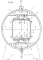
- the gas guiding devices 15 are arranged in the region of the openings 12 in such a way that, in the upper position lifted from the openings 12 (shown in FIG. 1 below), the pressure chamber 4 shuts off towards the heating chamber 6 and in the on the opening 12 lowered position (shown in Fig. 1 above) shuts off the suction chamber 11 to the heating chamber 6. Due to the fact that the gas guiding devices 15 in the upper position - shown in FIG. 2a - close the pressure chamber 4 towards the heating chamber 6, a dust pressure forms within the pressure chamber 4 when the cooling gas blower 3 is actuated. This dynamic pressure built up in the pressure chamber 4 can build up do not dismantle until a gas guide device 15 is lowered onto an opening 12, as shown in FIGS.
- the gas guide devices 15 are operated as follows during operation:
- the heating elements arranged in the heating chamber 6 are switched off and then the cooling gas blower 3 is switched on.
- the openings 12 in the heating chamber walls 5 are closed via the hatches 13 and the gas guide devices 15 are in the upper position which is lifted off the openings 12 and in which they connect shut off between the pressure chamber 4 and the heating chamber 6, as shown in Fig. 2a.
- the cooling gas blower By operating the cooling gas blower, a certain dynamic pressure of the cooling gas builds up in the pressure chamber 4.
- the hatches 13 are then opened via the hatch actuations 14, so that unhindered access to the heating chamber 6 is possible via the openings 12, as shown in FIG. 2b.
- a gas guiding device 15 is now lowered onto an opening 12, as illustrated in FIG. 2c.
- the access between the furnace chamber 6 and the suction chamber 11 is closed at the same time, so that the cooling gas accumulated in the pressure chamber 4 can only flow into the heating chamber 6.
- the gas guide elements 17 arranged in the gas guiding devices 15 are designed as plates 19 provided with nozzles 18.
- the use of nozzles 18 as gas guiding elements 17 is particularly advantageous, since this enables a targeted cooling gas flow onto the charge 7 that has a predeterminable penetration depth.
- the heating chamber 6 is flooded via the cooling gas flowing in from the pressure chamber 4.
- the hot furnace gas and the heated cooling gas are sucked out through the opposite opening 12 to the suction chamber 11, since on this side the gas guide device 15 is in the upper position, in which there is an unimpeded connection between the heating chamber 6 and the suction chamber 11.
- the cooling gas is cooled back via the heat exchanger 10 arranged in the gas cooling device 9 and reaches the heating chamber 6 again via the pressure chamber 4.
Abstract
Description
Die Erfindung betrifft einen Ofen zur Wärmebehandlung von Chargen metallischer Werkstücke, insbesondere einen Vakuumofen, mit einem Ofengehäuse und einer darin unter Freilassung eines in eine äußere und eine innere Kammer unterteilten Zwischenraumes ausgebildeten Heizkammer, sowie mit einer innerhalb des Ofengehäuses angeordneten Gaskühleinrichtung, die über die Kammern und in mindestens zwei Heizkammerwänden ausgebildeten verschließbaren Öffnungen mit der Heizkammer zur Zu- und Abfuhr von Kühlgas verbunden ist.The invention relates to a furnace for the heat treatment of batches of metallic workpieces, in particular a vacuum furnace, with a furnace housing and a heating chamber formed therein, leaving a space divided into an outer and an inner chamber, and with a gas cooling device arranged inside the furnace housing, which passes over the chambers and is connected to the heating chamber for supplying and removing cooling gas in at least two closable openings formed in the heating chamber walls.
Öfen der voranstehend beschriebenen Art sind in verschiedenen Ausführungsformen bekannt. Aus dem DE-Gebrauchsmuster 93 11 985 ist beispielsweise ein Ofen bekannt, bei dem die in den Heizkammerwänden ausgebildeten Öffnungen mittels einer Lukenmechanik bzw. einer verdrehbaren Ringplatte geöffnet und verschlossen werden können. Über die relativ weit von der abzukühlenden Charge entfernten Öffnungen kann zwar das Kühlgas ungehindert in die Heizkammer eindringen, jedoch weist der in die Heizkammer eindringende Kühlgasstrahl keine große Eindringtiefe auf, da einerseits der Durchmesser D der Öffnung sehr groß und die Düsenlänge L sehr klein ist. Dadurch kommt es nicht zur Ausbildung eines echten Gasstrahls bzw. nur eines sehr kurzen Strahls. Andererseits ist die Entfernung zwischen der Öffnung und der Charge sehr groß ist, so daß sich der Kühlgasstrahl bis zum Auftreffen auf die Charge aufgelöst hat. Eine größere Kühlwirkung des Gases kann bei einem solchermaßen ausgebildeten Ofen nur durch die Erhöhung der Gasgeschwindigkeit und somit der Leistung des Kühlgasgebläses erreicht werden, was wiederum größere und teurere Gebläsemotoren zur Folge hat.Ovens of the type described above are known in various embodiments. From DE utility model 93 11 985, for example, an oven is known in which the openings formed in the heating chamber walls can be opened and closed by means of a hatch mechanism or a rotatable ring plate. The cooling gas can penetrate the heating chamber unhindered via the openings which are relatively far away from the batch to be cooled, but the cooling gas jet entering the heating chamber does not have a large depth of penetration, since on the one hand the diameter D of the opening is very large and the nozzle length L is very small. This does not result in the formation of a real gas jet or only a very short jet. On the other hand, the distance between the opening and the batch is very large, so that the cooling gas jet has broken up until it hits the batch. A greater cooling effect of the gas can only be achieved in such an oven by increasing the gas velocity and thus the performance of the Cooling gas blower can be achieved, which in turn results in larger and more expensive blower motors.
Weiterhin ist es aus der Praxis bekannt, oberhalb der Öffnungen Gaseintrittsdüsen anzuordnen, über welche das Kühlgas in die Heizkammer eingeleitet wird. Diese Düsen sind von der Charge weit entfernt. Um dennoch mit dem Kernstrahl bis in die Charge zu treffen, müssen große Düsendurchmesser gewählt werden, da die Eindringtiefe proportional zum Düsendurchmesser ist. Es wird damit für diese bekannte Anordnung eine hohe Leistung des Kühlgasgebläses benötigt, um vor dem Düseneintritt den erforderlichen hohen Staudruck zu erzeugen.Furthermore, it is known from practice to arrange gas inlet nozzles above the openings, via which the cooling gas is introduced into the heating chamber. These nozzles are far from the batch. In order to still hit the core jet into the batch, large nozzle diameters must be selected, since the depth of penetration is proportional to the nozzle diameter. This known arrangement therefore requires a high cooling gas blower output in order to generate the required high dynamic pressure before the nozzle enters.
Um ohne Erhöhung der Kühlgasgebläseleistung einen gewissen Staudruck aufbauen zu können, ist es weiterhin aus der Praxis bekannt, im Bereich der Öffnungen in den Heizkammerwänden mit Bohrungen versehene Lochplatten vorzusehen. Dadurch, daß der durch die in den Lochplatten angeordneten Bohrungen verbleibende offene Querschnitt der Öffnungen in den Heizkammerwänden nur noch rund 40 % beträgt, wird bei gleichbleibender Kühlgasgebläseleistung automatisch ein gewisser Staudruck auf der Anströmseite der Lochplatte erzeugt, was die Geschwindigkeitserhöhung der durch die Bohrungen der Lochplatte in die Heizkammer eintretenden Kühlgasstrahlen zur Folge hat. Neben dem hohen Widerstand auf der Anströmseite der Lochplatte ist es bei dieser bekannten Ausbildung nachteilig, daß die in der Lochplatte ausgebildeten Bohrungen keinen Kernstrahl erzeugen, wie er aus der Düsenströmung bekannt ist. Die aus den Bohrungen der Lochplatte austretende Strömung divergiert sehr stark, so daß schon in einer kurzen Entfernung hinter den Bohrungen kein Strahl mehr feststellbar ist.In order to be able to build up a certain dynamic pressure without increasing the cooling gas blower output, it is also known from practice to provide perforated plates with holes in the area of the openings in the heating chamber walls. Due to the fact that the open cross-section of the openings in the heating chamber walls remaining through the holes arranged in the perforated plates is only around 40%, a certain dynamic pressure is automatically generated on the upstream side of the perforated plate with constant cooling gas blower output, which increases the speed of the through the holes in the perforated plate cooling gas jets entering the heating chamber. In addition to the high resistance on the upstream side of the perforated plate, it is disadvantageous in this known design that the bores formed in the perforated plate do not generate a core jet, as is known from the nozzle flow. The flow emerging from the holes in the perforated plate diverges very strongly, so that a jet can no longer be detected even at a short distance behind the holes.
Nachteilig ist bei diesen Öfen mit Wechselkühlung von oben nach unten (und umgekehrt) weiterhin, daß das Gas beim Verlassen des Chargenraumes nicht frei abströmen kann, da es noch einmal den Widerstand einer Lochplatte zu überwinden hat. Dafür ist es erforderlich, erneut eine höhere Gebläseleistung aufzuwenden.Another disadvantage of these furnaces with alternating cooling from top to bottom (and vice versa) is that the gas cannot flow freely when leaving the batch space, since it has to overcome the resistance of a perforated plate once again. For this it is necessary to use a higher fan power again.
Der Erfindung liegt die Aufgabe zugrunde, unter Meidung der voranstehend genannten Nachteile einen Ofen zur Wärmebehandlung von Chargen metallischer Werkstücke zu schaffen, der ohne Erhöhung der Kühlgasgebläseleistung eine gezielte Abkühlung der in der Ofenkammer angeordneten Charge mit hoher Eindringtiefe ermöglicht.The invention has for its object to avoid the disadvantages mentioned above, a furnace for heat treatment To create batches of metallic workpieces that allow targeted cooling of the batch arranged in the furnace chamber with a high penetration depth without increasing the cooling gas blower output.
Die technische Lösung dieser Aufgabe ist dadurch gekennzeichnet, daß die äußere, die Heizkammer umgebende Kammer als Druckkammer eines Kühlgasgebläses und die innere, zwischen Heizkammer und Gaskühleinrichtung angeordnete Kammer als Saugkammer des Kühlgasgebläses ausgebildet ist und daß im Bereich der Öffnungen Gasleiteinrichtungen höhenverstellbar so angeordnet sind, daß diese in der von den Öffnungen abgehobenen oberen Position die Druckkammer zur Heizkammer hin absperren und in der auf die Öffnungen abgesenkten Position die Saugkammer zur Heizkammer hin absperren. Durch die Ausbildung von höhenverstellbaren Gasleiteinrichtungen im Bereich der in den Heizkammerwänden vorgesehenen Öffnungen ist es vorteilhafterweise möglich, diese Gasleiteinrichtungen bis nahe an die abzukühlende Charge heran zu verfahren, so daß eine gezielte Abkühlung der Charge möglich ist. Eine ausreichend hohe Anströmgeschwindigkeit bei gleichbleibender Kühlgasgebläseleistung wird darüber hinaus dadurch erreicht, daß die die Heizkammer umgebende Kammer als Druckkammer des Kühlgasgebläses ausgebildet ist. In der von den Öffnungen abgehobenen oberen Position der Gasleiteinrichtungen wird der Zugang der Druckkammer zur Heizkammer hin verschlossen, so daß sich bei laufendem Kühlgasgebläse ein gewisser Staudruck ausbildet. Beim Herabfahren der Gasleiteinrichtungen nach dem Öffnen der in den Heizkammerwänden ausgebildeten Öffnungen wird dieser in der Druckkammer aufgebaute Staudruck freigegeben, so daß über die bis nahe an die Oberfläche der abzukühlenden Charge heranverfahrbaren Gasleiteinrichtungen eine gezielte Abkühlung mit hoher Eindringtiefe ermöglicht wird.The technical solution to this problem is characterized in that the outer chamber surrounding the heating chamber is designed as a pressure chamber of a cooling gas blower and the inner chamber arranged between the heating chamber and gas cooling device is designed as a suction chamber of the cooling gas blower and in the area of the openings gas guiding devices are arranged such that they are adjustable in height so that shut off the pressure chamber towards the heating chamber in the upper position lifted off the openings and shut off the suction chamber towards the heating chamber in the position lowered onto the openings. Due to the formation of height-adjustable gas guide devices in the area of the openings provided in the heating chamber walls, it is advantageously possible to move these gas guide devices close to the batch to be cooled, so that a targeted cooling of the batch is possible. A sufficiently high flow velocity with constant cooling gas blower output is also achieved in that the chamber surrounding the heating chamber is designed as a pressure chamber of the cooling gas blower. In the upper position of the gas guiding devices which is lifted from the openings, the access of the pressure chamber to the heating chamber is closed, so that a certain dynamic pressure builds up while the cooling gas fan is running. When the gas guiding devices are lowered after opening the openings formed in the heating chamber walls, this dynamic pressure built up in the pressure chamber is released, so that a targeted cooling with a high penetration depth is made possible by the gas guiding devices which can be moved close to the surface of the batch to be cooled.
Um eine an verschiedene Chargentypen angepaßte gezielte Abkühlung zu ermöglichen, besteht die Gasleiteinrichtung gemäß einer bevorzugten Ausführungsform der Erfindung aus einem kastenförmigen Tragrahmen, in den auswechselbare Gasführungselemente einsetzbar sind. Diese Auswechselbarkeit der Gasführungselemente ist besonders vorteilhaft, da hierdurch die Umrüstung des Ofens auf neue Chargentypen besonders schnell und einfach erfolgen kann.In order to enable targeted cooling adapted to different batch types, the gas guide device according to a preferred embodiment of the invention consists of a box-shaped support frame in which interchangeable gas guide elements can be used. This interchangeability of the gas guide elements is particularly advantageous because this means that the furnace can be converted to new batch types particularly quickly and easily.
Gemäß einer bevorzugten Ausführungsform der Erfindung ist das in die Gasleiteinrichtung einsetzbare Gasführungselement als eine mit Düsen versehene Platte ausgebildet. Um einen möglichst gleichmäßigen und eine hohe Eindringtiefe aufweisenden Kernstrahl zu erzielen, weisen die Düsen einen trichterförmigen Einströmbereich auf. Durch die Anordnung der Düsen in der höhenverstellbaren Gasleiteinrrichtung ist es somit möglich, durch die Auswahl des Düsendurchmessers und des Abstandes zwischen dem Düsenaustritt und der Chargenoberfläche die Eindringtiefe des Kernstrahls des Kühlgases in die Charge vorherbestimmbar einzustellen.According to a preferred embodiment of the invention, the gas guiding element that can be inserted into the gas guiding device is designed as a plate provided with nozzles. In order to achieve a core jet that is as uniform as possible and has a high penetration depth, the nozzles have a funnel-shaped inflow region. The arrangement of the nozzles in the height-adjustable gas guide device makes it possible, by selecting the nozzle diameter and the distance between the nozzle outlet and the batch surface, to predetermine the penetration depth of the core jet of the cooling gas into the batch.
Schließlich wird mit der Erfindung vorgeschlagen, daß das in die Gasleiteinrichtung einsetzbare Gasführungselement als ein mit einer Vielzahl von Bohrungen versehenes Gleichrichtergitter ausgebildet ist. Bei einem solchen Gleichrichtergitter handelt es sich um eine mit einer Vielzahl von Bohrungen versehene Platte, die etwa 90 % des offenen Querschnitts der in der Heizkammerwand ausgebildeten Öffnung freigibt. Die Verwendung eines solchen Gleichrichtergitters wird dadurch ermöglicht, daß durch die höhenverstellbare Gasleiteinrichtung zunächst ein gewisser Staudruck in der Druckkammer aufgebaut werden kann, so daß der auf das Gleichrichtergitter auftreffende Kühlgasstrom durch die Bohrungen in dem Gleichrichtergitter ohne wesentliche Geschwindigkeitsreduzierungen und Strömungswiderstände über die Breite der Öffnung vergleichmäßigt wird. Solche kostengünstig zu fertigende Gleichrichtergitter werden insbesondere verwendet, wenn keine großen Eindringtiefen benötigt werden.Finally, it is proposed with the invention that the gas guide element that can be inserted into the gas guiding device is designed as a rectifier grid provided with a plurality of bores. Such a rectifier grid is a plate provided with a multiplicity of bores, which exposes approximately 90% of the open cross section of the opening formed in the heating chamber wall. The use of such a rectifier grid is made possible by the fact that a certain dynamic pressure can first be built up in the pressure chamber by the height-adjustable gas guide device, so that the cooling gas flow impinging on the rectifier grid is evened out over the width of the opening through the holes in the rectifier grid without significant speed reductions and flow resistances becomes. Such rectifier gratings, which can be produced inexpensively, are used in particular when large penetration depths are not required.
Weitere Einzelheiten, Merkmale und Vorteile der Erfindung werden nachfolgend anhand der zugehörigen Zeichnung erläutert, in der ein Ausführungsbeispiel eines erfindungsgemäß ausgebildeten Ofens zur Wärmebehandlung von Chargen metallischer Werkstücke schematisch dargestellt ist. In der Zeichnung zeigt:
- Fig. 1
- einen Längsschnitt durch eine Ofenanlage;
- Fig. 2a
- einen Querschnitt entlang der Schnittlinie ll-ll in Fig. 1 geschnitten, die Luken in geschlossenem Zustand darstellend;
- Fig. 2b
- einen Querschnitt gemäß Fig. 2a, jedoch die Luken im geöffneten Zustand darstellend und
- Fig. 2c
- einen Querschnitt gemäß Fig. 2a und 2b, jedoch die Luken im geöffneten Zustand und mit einer abgesenkten Gasleiteinrichtung darstellend.
- Fig. 1
- a longitudinal section through an oven system;
- Fig. 2a
- a cross section along the section line II-II in Figure 1, showing the hatches in the closed state.
- Fig. 2b
- a cross section of FIG. 2a, but showing the hatches in the open state and
- Fig. 2c
- a cross section according to FIGS. 2a and 2b, but showing the hatches in the open state and with a lowered gas guide.
Die in Fig. 1 dargestellte Ofenanlage besteht im wesentlichen aus einem Ofengehäuse 1 sowie zwei druckdicht mit diesem Ofengehäuse 1 verschließbaren Hauben 2, wobei die linke Haube 2 zur Aufnahme eines - nicht dargestellten - Elektroantriebes für ein Kühlgasgebläse 3 dient. Innerhalb des Ofengehäuses 1 ist eine von einer äußeren Kammer 4 umgebene, von Heizkammerwänden 5 umschlossene Heizkammer 6 angeordnet. Zum Aufheizen der in der Heizkammer 6 einer Wärmebehandlung zu unterziehenden Charge 7 sind in der Heizkammer 6 - nicht dargestellte - Heizelemente angeordnet. Das Umwälzen der Ofenatmosphäre innerhalb der Heizkammer 6 erfolgt bei konvektiver Erwärmung über einen Ventilator 8.The furnace system shown in Fig. 1 consists essentially of a
Um die Heizkammer 6 mit Kühlgas fluten zu können bzw. heißes Ofengas aus der Heizkammer 6 abziehen zu können, ist innerhalb des Ofengehäuses 1 eine Gaskühleinrichtung 9 angeordnet, die aus dem Kühlgasgebläse 3 und einem Wärmetauscher 10 besteht. Ausgehend von der linken Haube 2 zur Aufnahme des Elektroantriebes für das Kühlgasgebläse 3 ist die äußere, die Heizkammer 6 umgebende Kammer 4 als mit der Druckseite des Kühlgasgebläses 3 verbundene Druckkammer ausgebildet, während eine innere, zwischen der Heizkammer 6 und der Gaskühleinrichtung 9 ausgebildete Kammer 11 als mit der Saugseite des Kühlgasgebläses 3 verbundene Saugkammer ausgebildet ist.In order to be able to flood the
Um die Heizkammer 6 über die Druckkammer 4 mit Kühlgas fluten zu können bzw. heißes Ofengas aus der Heizkammer 6 über die Saugkammer 11 abziehen zu können, weisen die Heizkammerwände 5 Öffnungen 12 auf, die zum Verbinden mit der Druckkammer 4 bzw. der Saugkammer 11 über Luken 13 geöffnet und verschlossen werden können. Diese Luken 13 sind über eine nicht näher beschriebene Lukenbetätigung 14 antreibbar.In order to be able to flood the
Zum gezielten Einleiten des Kühlgases in die Heizkammer 6 sind im Bereich der Öffnungen 12 in den Heizkammerwänden 5 höhenverstellbare Gasleiteinrichtungen 15 angeordnet. Bei dem dargestellten Ausführungsbeispiel bestehen die Gasleiteinrichtungen 15 jeweils aus einem Tragrahmen 16, in den auswechselbare Gasführungselemente 17 einsetzbar sind.In order to introduce the cooling gas into the
Wie aus Fig. 1 ersichtlich, sind die Gasleiteinrichtungen 15 so im Bereich der Öffnungen 12 angeordnet, daß diese in der von den Öffnungen 12 abgehobenen oberen Position (in Fig. 1 unten dargestellt) die Druckkammer 4 zur Heizkammer 6 hin absperrt und in der auf die Offnung 12 abgesenkten Position (in Fig. 1 oben dargestellt) die Saugkammer 11 zur Heizkammer 6 hin absperrt. Dadurch, daß die Gasleiteinrichtungen 15 in der oberen Position - dargestellt in Fig. 2a - die Druckkammer 4 zur Heizkammer 6 hin abschließen, bildet sich bei der Betätigung des Kühlgasgebläses 3 ein Staubdruck innerhalb der Druckkammer 4. Dieser in der Druckkammer 4 aufgebaute Staudruck kann sich erst abbauen, wenn eine Gasleiteinrichtung 15 auf eine Öffnung 12 abgesenkt wird, wie dies in Fig. 1 und 2c dargestellt ist. In dieser Stellung kann das Kühlgas aus der Druckkammer 4 kommend in die Heizkammer 6 einströmen. Auf der gegenüberliegenden Seite ist die Gasleiteinrichtung 15 noch in der oberen, die Druckkammer 4 verschließenden Stellung. Somit ist auf dieser Seite der Zugang von der Heizkammer 6 hin zur Saugkammer 11 offen, so daß das heiße Ofengas über die Saugkammer 11 abgesaugt werden kann.As can be seen from FIG. 1, the
Das Verfahren der Gasleiteinrichtungen 15 erfolgt im Betrieb folgendermaßen:The
Nach der Wärmebehandlung der in der Heizkammer 6 angeordneten Charge 7 werden die in der Heizkammer 6 angeordneten Heizelemente abgeschaltet und anschließend das Kühlgasgebläse 3 eingeschaltet. Bei diesem Betriebszustand sind die Öffnungen 12 in den Heizkammerwänden 5 über die Luken 13 verschlossen und befinden sich die Gasleitereinrichtungen 15 in der von den Öffnungen 12 abgehobenen oberen Position, in der diese die Verbindung zwischen der Druckkammer 4 und der Heizkammer 6 absperren, wie dies in Fig. 2a dargestellt ist. Durch die Betätigung des Kühlgasgebläses baut sich in der Druckkammer 4 ein gewisser Staudruck des Kühlgases auf. Anschließend werden über die Lukenbetätigungen 14 die Luken 13 geöffnet, so daß ein ungehinderter Zugang zur Heizkammer 6 über die Öffnungen 12 möglich ist, wie dies in Fig. 2b dargestellt ist. Um die Heizkammer 6 mit dem Kühlgas aus der Druckkammer 4 zu fluten, wird nunmehr eine Gasleiteinrichtung 15 auf eine Öffnung 12 abgesenkt, wie dies die Abbildung 2c verdeutlicht. Durch das Absenken dieser Gasleiteinrichtung 15 wird an dieser Stelle gleichzeitig der Zugang zwischen der Ofenkammer 6 und der Saugkammer 11 verschlossen, so daß das in der Druckkammer 4 angestaute Kühlgas nur in die Heizkammer 6 einströmen kann.After the heat treatment of the
Bei dem in den Abbildungen Fig. 1 bis Fig. 2c dargestellten Ausführungsbeispiel sind die in den Gasleiteinrichtungen 15 angeordneten Gasführungselemente 17 als mit Düsen 18 versehene Platten 19 ausgebildet. Die Verwendung von Düsen 18 als Gasführungselemente 17 ist besonders vorteilhaft, da hiermit eine gezielte und eine vorbestimmbare Eindringtiefe aufweisende Kühlgasströmung auf die Charge 7 möglich ist.In the exemplary embodiment shown in FIGS. 1 to 2c, the
Bei der in Fig. 2c dargestellten Betriebsstellung wird die Heizkammer 6 über das aus der Druckkammer 4 einströmende Kühlgas geflutet. Das heiße Ofengas sowie das aufgeheizte Kühlgas werden über die gegenüberliegende Öffnung 12 zur Saugkammer 11 hin abgesaugt, da auf dieser Seite die Gasleiteinrichtung 15 sich in der oberen Position befindet, in der eine ungehinderte Verbindung zwischen der Heizkammer 6 und der Saugkammer 11 besteht. Über den in der Gaskühleinrichtung 9 angeordneten Wärmetauscher 10 wird das Kühlgas zurückgekühlt und gelangt über die Druckkammer 4 erneut in die Heizkammer 6.In the operating position shown in FIG. 2c, the
Mit einer solchermaßen ausgestalteten Ofenanlage ist eine gezielte Abkühlung der in der Heizkammer 6 angeordneten Charge 7 mit einer vorbestimmbaren Eindringtiefe möglich, ohne daß es einer Erhöhung der Motorleistung des Kühlgasgebläses 3 bedarf.With a furnace system designed in this way, targeted cooling of the
- 11
- OfengehäuseFurnace housing
- 22nd
- HaubeHood
- 33rd
- KühlgasgebläseCooling gas blower
- 44th
- äußere Kammer (Druckkammer)outer chamber (pressure chamber)
- 55
- HeizkammerwandHeating chamber wall
- 66
- HeizkammerHeating chamber
- 77
- ChargeBatch
- 88th
- Ventilatorfan
- 99
- GaskühleinrichtungGas cooling device
- 1010th
- WärmetauscherHeat exchanger
- 1111
- innere Kammer (Saugkammer)inner chamber (suction chamber)
- 1212th
- Öffnungopening
- 1313
- Lukehatch
- 1414
- LukenbetätigungHatch control
- 1515
- GasleiteinrichtungGas guiding device
- 1616
- TragrahmenSupport frame
- 1717th
- GasführungselementThrottle element
- 1818th
- Düsejet
- 1919th
- Platteplate
Claims (5)
daß die äußere, die Heizkammer (6) umgebende Kammer (4) als Druckkammer eines Kühlgasgebläses (3) und die innere, zwischen Heizkammer (6) und Gaskühleinrichtung (9) angeordnete Kammer (11) als Saugkammer des Kühlgasgebläses (3) ausgebildet ist und daß im Bereich der Öffnungen (12) Gasleiteinrichtungen (15) höhenverstellbar so angeordnet sind, daß diese in der von den Öffnungen (12) abgehobenen oberen Position die Druckkammer (4) zur Heizkammer (6) hin absperren und in der auf die Öffnungen (12) abgesenkten Position die Saugkammer (11) zur Heizkammer (6) hin absperren.Furnace for the heat treatment of batches of metallic workpieces, in particular vacuum furnace, with a furnace housing (1) and a heating chamber (6) formed therein, leaving an intermediate space divided into an outer and an inner chamber (4, 11), as well as with a inside the furnace housing ( 1) arranged gas cooling device (9) which is connected to the heating chamber (6) for supplying and removing cooling gas via the chambers (4, 11) and closable openings (12) formed in at least two heating chamber walls (5), characterized in that
that the outer chamber (4) surrounding the heating chamber (6) is designed as a pressure chamber of a cooling gas blower (3) and the inner chamber (11) arranged between the heating chamber (6) and gas cooling device (9) is designed as a suction chamber of the cooling gas blower (3) and that gas guide devices (15) are arranged such that they can be adjusted in height in the area of the openings (12) in such a way that in the upper position raised from the openings (12) they shut off the pressure chamber (4) to the heating chamber (6) and in that on the openings (12 ) in the lowered position, shut off the suction chamber (11) towards the heating chamber (6).
Applications Claiming Priority (2)
| Application Number | Priority Date | Filing Date | Title |
|---|---|---|---|
| DE19526676 | 1995-07-21 | ||
| DE19526676 | 1995-07-21 |
Publications (2)
| Publication Number | Publication Date |
|---|---|
| EP0754768A1 true EP0754768A1 (en) | 1997-01-22 |
| EP0754768B1 EP0754768B1 (en) | 2001-06-13 |
Family
ID=7767437
Family Applications (2)
| Application Number | Title | Priority Date | Filing Date |
|---|---|---|---|
| EP96710008A Withdrawn EP0754769A1 (en) | 1995-07-21 | 1996-07-13 | Furnace for heat treating batches of metal workpieces |
| EP96710009A Expired - Lifetime EP0754768B1 (en) | 1995-07-21 | 1996-07-13 | Furnace for heat treating batches of metal workpieces |
Family Applications Before (1)
| Application Number | Title | Priority Date | Filing Date |
|---|---|---|---|
| EP96710008A Withdrawn EP0754769A1 (en) | 1995-07-21 | 1996-07-13 | Furnace for heat treating batches of metal workpieces |
Country Status (4)
| Country | Link |
|---|---|
| EP (2) | EP0754769A1 (en) |
| AT (1) | ATE202152T1 (en) |
| DE (2) | DE59607067D1 (en) |
| ES (1) | ES2159710T3 (en) |
Cited By (3)
| Publication number | Priority date | Publication date | Assignee | Title |
|---|---|---|---|---|
| FR2864106A1 (en) * | 2003-12-23 | 2005-06-24 | Etudes Const Mecaniques | Quenching device for quenching components, notably of heat treated steel, with the circulation of a high pressure quenching gas |
| US8088328B2 (en) | 2008-06-13 | 2012-01-03 | Jones William R | Vacuum nitriding furnace |
| WO2017041774A1 (en) * | 2015-09-09 | 2017-03-16 | Ipsen International Gmbh | Device for treating metal workpieces with cooling gas |
Families Citing this family (5)
| Publication number | Priority date | Publication date | Assignee | Title |
|---|---|---|---|---|
| DE19820083A1 (en) * | 1998-05-06 | 1999-11-11 | Ald Vacuum Techn Gmbh | Process for quenching workpieces and heat treatment system for carrying out the process |
| US6533991B1 (en) * | 2000-06-20 | 2003-03-18 | Ipsen International, Inc. | Cooling gas injection nozzle for a vacuum heat treating furnace |
| JP4573290B2 (en) * | 2003-10-17 | 2010-11-04 | 株式会社Ihi | High pressure heat treatment furnace |
| DE102009052900A1 (en) | 2009-11-13 | 2011-05-19 | Ipsen International Gmbh | Method and device for conducting flow in industrial furnaces for the heat treatment of metallic materials / workpieces |
| WO2012037905A1 (en) | 2010-09-24 | 2012-03-29 | Ipsen International Gmbh | Method and device for conducting the flow in industrial furnaces for the thermal treatment of metal materials/workpieces |
Citations (6)
| Publication number | Priority date | Publication date | Assignee | Title |
|---|---|---|---|---|
| DE3208574A1 (en) * | 1982-03-10 | 1983-09-22 | Schmetz Industrieofenbau und Vakuum-Hartlöttechnik KG, 5750 Menden | Vacuum shaft furnace |
| DE3215509A1 (en) * | 1982-04-26 | 1983-10-27 | Schmetz Industrieofenbau und Vakuum-Hartlöttechnik KG, 5750 Menden | Vacuum chamber oven |
| DE3321554C1 (en) * | 1982-07-16 | 1984-02-16 | Ipsen Industries International Gmbh, 4190 Kleve | Industrial furnace for heat-treatment of metal workpieces |
| GB2152199A (en) * | 1983-12-23 | 1985-07-31 | Ipsen Ind Int Gmbh | Industrial furnace |
| DE9311985U1 (en) * | 1993-08-11 | 1993-10-14 | Ipsen Ind Int Gmbh | Furnace for the heat treatment of batches of metallic work pieces |
| DE9400222U1 (en) * | 1994-01-08 | 1994-02-24 | Ipsen Ind Int Gmbh | Multi-chamber furnace with combined cooling |
Family Cites Families (2)
| Publication number | Priority date | Publication date | Assignee | Title |
|---|---|---|---|---|
| DE3224971A1 (en) * | 1982-07-03 | 1984-01-05 | Schmetz Industrieofenbau und Vakuum-Hartlöttechnik KG, 5750 Menden | Vacuum shaft furnace |
| FR2651307B1 (en) * | 1989-08-29 | 1993-12-17 | Traitement Sous Vide | HEAT TREATMENT OVEN EQUIPPED WITH IMPROVED COOLING MEANS. |
-
1996
- 1996-07-13 AT AT96710009T patent/ATE202152T1/en not_active IP Right Cessation
- 1996-07-13 EP EP96710008A patent/EP0754769A1/en not_active Withdrawn
- 1996-07-13 DE DE59607067T patent/DE59607067D1/en not_active Expired - Fee Related
- 1996-07-13 EP EP96710009A patent/EP0754768B1/en not_active Expired - Lifetime
- 1996-07-13 ES ES96710009T patent/ES2159710T3/en not_active Expired - Lifetime
- 1996-07-13 DE DE1996128383 patent/DE19628383A1/en not_active Withdrawn
Patent Citations (6)
| Publication number | Priority date | Publication date | Assignee | Title |
|---|---|---|---|---|
| DE3208574A1 (en) * | 1982-03-10 | 1983-09-22 | Schmetz Industrieofenbau und Vakuum-Hartlöttechnik KG, 5750 Menden | Vacuum shaft furnace |
| DE3215509A1 (en) * | 1982-04-26 | 1983-10-27 | Schmetz Industrieofenbau und Vakuum-Hartlöttechnik KG, 5750 Menden | Vacuum chamber oven |
| DE3321554C1 (en) * | 1982-07-16 | 1984-02-16 | Ipsen Industries International Gmbh, 4190 Kleve | Industrial furnace for heat-treatment of metal workpieces |
| GB2152199A (en) * | 1983-12-23 | 1985-07-31 | Ipsen Ind Int Gmbh | Industrial furnace |
| DE9311985U1 (en) * | 1993-08-11 | 1993-10-14 | Ipsen Ind Int Gmbh | Furnace for the heat treatment of batches of metallic work pieces |
| DE9400222U1 (en) * | 1994-01-08 | 1994-02-24 | Ipsen Ind Int Gmbh | Multi-chamber furnace with combined cooling |
Cited By (4)
| Publication number | Priority date | Publication date | Assignee | Title |
|---|---|---|---|---|
| FR2864106A1 (en) * | 2003-12-23 | 2005-06-24 | Etudes Const Mecaniques | Quenching device for quenching components, notably of heat treated steel, with the circulation of a high pressure quenching gas |
| US8088328B2 (en) | 2008-06-13 | 2012-01-03 | Jones William R | Vacuum nitriding furnace |
| WO2017041774A1 (en) * | 2015-09-09 | 2017-03-16 | Ipsen International Gmbh | Device for treating metal workpieces with cooling gas |
| US10934599B2 (en) | 2015-09-09 | 2021-03-02 | Ipsen, Inc. | Device for treating metal workpieces with cooling gas |
Also Published As
| Publication number | Publication date |
|---|---|
| ES2159710T3 (en) | 2001-10-16 |
| DE19628383A1 (en) | 1997-02-06 |
| EP0754768B1 (en) | 2001-06-13 |
| DE59607067D1 (en) | 2001-07-19 |
| EP0754769A1 (en) | 1997-01-22 |
| ATE202152T1 (en) | 2001-06-15 |
Similar Documents
| Publication | Publication Date | Title |
|---|---|---|
| DE2844843C2 (en) | Industrial furnace for the heat treatment of metallic workpieces | |
| EP0151700B1 (en) | Industrial furnace, especially a multiple chamber vacuum furnace, for heat treating batches of metal workpieces | |
| DE3215509C2 (en) | ||
| EP2312953B1 (en) | Oven with a steam system | |
| DE2637646A1 (en) | WAREHOUSE | |
| EP3397782B1 (en) | Device for treating metal workpieces with cooling gas | |
| EP0754768B1 (en) | Furnace for heat treating batches of metal workpieces | |
| EP1154024B1 (en) | Process and device for heat treating metallic workpieces | |
| DE10148548C5 (en) | oven | |
| DE10210952B4 (en) | Apparatus for treating metallic workpieces with cooling gas | |
| DE3224971C2 (en) | ||
| EP2330325A2 (en) | Retort furnace for thermal treatment of metallic workpieces | |
| DE2501360B2 (en) | Vacuum atmosphere furnace for the heat treatment of workpieces | |
| DE3819803C1 (en) | ||
| WO2012037905A1 (en) | Method and device for conducting the flow in industrial furnaces for the thermal treatment of metal materials/workpieces | |
| EP0864519A1 (en) | Apparatus to guide webs in a floating manner | |
| DE4034085C1 (en) | ||
| DE19538364C5 (en) | Device for rapid heating of metal press studs | |
| DE705764C (en) | Pull-through shaft furnace with heat recovery | |
| DE3130064C2 (en) | oven | |
| DE3842372C2 (en) | Device for the heat treatment of metallic workpieces | |
| DE202008011194U1 (en) | Retort oven for the heat treatment of metallic workpieces | |
| DE10038782C1 (en) | Process for cooling, especially quenching and hardening metallic workpieces, especially steel in a cooling chamber comprises circulating parallel cooling gas streams over the workpiece and a heat exchanger | |
| DE887357C (en) | Device for operating a through furnace with preheating chamber, heating chamber and cooling chamber | |
| DE102012008804A1 (en) | Continuous heat treatment furnace with increased cooling capacity of its cooling zone and method thereof |
Legal Events
| Date | Code | Title | Description |
|---|---|---|---|
| PUAI | Public reference made under article 153(3) epc to a published international application that has entered the european phase |
Free format text: ORIGINAL CODE: 0009012 |
|
| AK | Designated contracting states |
Kind code of ref document: A1 Designated state(s): AT CH DE ES FR GB IT LI |
|
| 17P | Request for examination filed |
Effective date: 19970109 |
|
| RAP1 | Party data changed (applicant data changed or rights of an application transferred) |
Owner name: IPSEN INTERNATIONAL GMBH |
|
| 17Q | First examination report despatched |
Effective date: 19991102 |
|
| GRAG | Despatch of communication of intention to grant |
Free format text: ORIGINAL CODE: EPIDOS AGRA |
|
| GRAG | Despatch of communication of intention to grant |
Free format text: ORIGINAL CODE: EPIDOS AGRA |
|
| GRAH | Despatch of communication of intention to grant a patent |
Free format text: ORIGINAL CODE: EPIDOS IGRA |
|
| GRAH | Despatch of communication of intention to grant a patent |
Free format text: ORIGINAL CODE: EPIDOS IGRA |
|
| GRAA | (expected) grant |
Free format text: ORIGINAL CODE: 0009210 |
|
| AK | Designated contracting states |
Kind code of ref document: B1 Designated state(s): AT CH DE ES FR GB IT LI |
|
| REF | Corresponds to: |
Ref document number: 202152 Country of ref document: AT Date of ref document: 20010615 Kind code of ref document: T |
|
| REG | Reference to a national code |
Ref country code: CH Ref legal event code: NV Representative=s name: E. BLUM & CO. PATENTANWAELTE * E. BLUM & CO. PATEN |
|
| ET | Fr: translation filed | ||
| REF | Corresponds to: |
Ref document number: 59607067 Country of ref document: DE Date of ref document: 20010719 |
|
| ITF | It: translation for a ep patent filed |
Owner name: ING. ZINI MARANESI & C. S.R.L. |
|
| GBT | Gb: translation of ep patent filed (gb section 77(6)(a)/1977) |
Effective date: 20010817 |
|
| REG | Reference to a national code |
Ref country code: ES Ref legal event code: FG2A Ref document number: 2159710 Country of ref document: ES Kind code of ref document: T3 |
|
| REG | Reference to a national code |
Ref country code: GB Ref legal event code: IF02 |
|
| PLBE | No opposition filed within time limit |
Free format text: ORIGINAL CODE: 0009261 |
|
| STAA | Information on the status of an ep patent application or granted ep patent |
Free format text: STATUS: NO OPPOSITION FILED WITHIN TIME LIMIT |
|
| 26N | No opposition filed | ||
| PGFP | Annual fee paid to national office [announced via postgrant information from national office to epo] |
Ref country code: GB Payment date: 20030704 Year of fee payment: 8 |
|
| PGFP | Annual fee paid to national office [announced via postgrant information from national office to epo] |
Ref country code: CH Payment date: 20030708 Year of fee payment: 8 |
|
| PGFP | Annual fee paid to national office [announced via postgrant information from national office to epo] |
Ref country code: ES Payment date: 20030718 Year of fee payment: 8 |
|
| PG25 | Lapsed in a contracting state [announced via postgrant information from national office to epo] |
Ref country code: GB Free format text: LAPSE BECAUSE OF NON-PAYMENT OF DUE FEES Effective date: 20040713 |
|
| PG25 | Lapsed in a contracting state [announced via postgrant information from national office to epo] |
Ref country code: ES Free format text: LAPSE BECAUSE OF NON-PAYMENT OF DUE FEES Effective date: 20040714 |
|
| PG25 | Lapsed in a contracting state [announced via postgrant information from national office to epo] |
Ref country code: LI Free format text: LAPSE BECAUSE OF NON-PAYMENT OF DUE FEES Effective date: 20040731 Ref country code: CH Free format text: LAPSE BECAUSE OF NON-PAYMENT OF DUE FEES Effective date: 20040731 |
|
| GBPC | Gb: european patent ceased through non-payment of renewal fee |
Effective date: 20040713 |
|
| REG | Reference to a national code |
Ref country code: CH Ref legal event code: PL |
|
| PGFP | Annual fee paid to national office [announced via postgrant information from national office to epo] |
Ref country code: AT Payment date: 20050628 Year of fee payment: 10 |
|
| PGFP | Annual fee paid to national office [announced via postgrant information from national office to epo] |
Ref country code: FR Payment date: 20050712 Year of fee payment: 10 |
|
| PG25 | Lapsed in a contracting state [announced via postgrant information from national office to epo] |
Ref country code: IT Free format text: LAPSE BECAUSE OF NON-PAYMENT OF DUE FEES Effective date: 20050713 |
|
| REG | Reference to a national code |
Ref country code: ES Ref legal event code: FD2A Effective date: 20040714 |
|
| PG25 | Lapsed in a contracting state [announced via postgrant information from national office to epo] |
Ref country code: AT Free format text: LAPSE BECAUSE OF NON-PAYMENT OF DUE FEES Effective date: 20060713 |
|
| REG | Reference to a national code |
Ref country code: FR Ref legal event code: ST Effective date: 20070330 |
|
| PGFP | Annual fee paid to national office [announced via postgrant information from national office to epo] |
Ref country code: DE Payment date: 20070816 Year of fee payment: 12 |
|
| PG25 | Lapsed in a contracting state [announced via postgrant information from national office to epo] |
Ref country code: FR Free format text: LAPSE BECAUSE OF NON-PAYMENT OF DUE FEES Effective date: 20060731 |
|
| PG25 | Lapsed in a contracting state [announced via postgrant information from national office to epo] |
Ref country code: DE Free format text: LAPSE BECAUSE OF NON-PAYMENT OF DUE FEES Effective date: 20090203 |