EP0754768A1 - Four pour le traitement thermique de charges de pièces métalliques - Google Patents
Four pour le traitement thermique de charges de pièces métalliques Download PDFInfo
- Publication number
- EP0754768A1 EP0754768A1 EP96710009A EP96710009A EP0754768A1 EP 0754768 A1 EP0754768 A1 EP 0754768A1 EP 96710009 A EP96710009 A EP 96710009A EP 96710009 A EP96710009 A EP 96710009A EP 0754768 A1 EP0754768 A1 EP 0754768A1
- Authority
- EP
- European Patent Office
- Prior art keywords
- chamber
- gas
- heating chamber
- furnace
- cooling
- Prior art date
- Legal status (The legal status is an assumption and is not a legal conclusion. Google has not performed a legal analysis and makes no representation as to the accuracy of the status listed.)
- Granted
Links
Images


Classifications
-
- C—CHEMISTRY; METALLURGY
- C21—METALLURGY OF IRON
- C21D—MODIFYING THE PHYSICAL STRUCTURE OF FERROUS METALS; GENERAL DEVICES FOR HEAT TREATMENT OF FERROUS OR NON-FERROUS METALS OR ALLOYS; MAKING METAL MALLEABLE, e.g. BY DECARBURISATION OR TEMPERING
- C21D1/00—General methods or devices for heat treatment, e.g. annealing, hardening, quenching or tempering
- C21D1/74—Methods of treatment in inert gas, controlled atmosphere, vacuum or pulverulent material
- C21D1/767—Methods of treatment in inert gas, controlled atmosphere, vacuum or pulverulent material with forced gas circulation; Reheating thereof
-
- C—CHEMISTRY; METALLURGY
- C21—METALLURGY OF IRON
- C21D—MODIFYING THE PHYSICAL STRUCTURE OF FERROUS METALS; GENERAL DEVICES FOR HEAT TREATMENT OF FERROUS OR NON-FERROUS METALS OR ALLOYS; MAKING METAL MALLEABLE, e.g. BY DECARBURISATION OR TEMPERING
- C21D1/00—General methods or devices for heat treatment, e.g. annealing, hardening, quenching or tempering
- C21D1/74—Methods of treatment in inert gas, controlled atmosphere, vacuum or pulverulent material
- C21D1/773—Methods of treatment in inert gas, controlled atmosphere, vacuum or pulverulent material under reduced pressure or vacuum
-
- F—MECHANICAL ENGINEERING; LIGHTING; HEATING; WEAPONS; BLASTING
- F27—FURNACES; KILNS; OVENS; RETORTS
- F27B—FURNACES, KILNS, OVENS, OR RETORTS IN GENERAL; OPEN SINTERING OR LIKE APPARATUS
- F27B5/00—Muffle furnaces; Retort furnaces; Other furnaces in which the charge is held completely isolated
- F27B5/06—Details, accessories, or equipment peculiar to furnaces of these types
- F27B5/16—Arrangements of air or gas supply devices
-
- F—MECHANICAL ENGINEERING; LIGHTING; HEATING; WEAPONS; BLASTING
- F27—FURNACES; KILNS; OVENS; RETORTS
- F27B—FURNACES, KILNS, OVENS, OR RETORTS IN GENERAL; OPEN SINTERING OR LIKE APPARATUS
- F27B5/00—Muffle furnaces; Retort furnaces; Other furnaces in which the charge is held completely isolated
- F27B5/06—Details, accessories, or equipment peculiar to furnaces of these types
- F27B5/14—Arrangements of heating devices
- F27B2005/143—Heating rods disposed in the chamber
-
- F—MECHANICAL ENGINEERING; LIGHTING; HEATING; WEAPONS; BLASTING
- F27—FURNACES; KILNS; OVENS; RETORTS
- F27B—FURNACES, KILNS, OVENS, OR RETORTS IN GENERAL; OPEN SINTERING OR LIKE APPARATUS
- F27B5/00—Muffle furnaces; Retort furnaces; Other furnaces in which the charge is held completely isolated
- F27B5/06—Details, accessories, or equipment peculiar to furnaces of these types
- F27B5/16—Arrangements of air or gas supply devices
- F27B2005/161—Gas inflow or outflow
- F27B2005/162—Gas inflow or outflow through closable or non-closable openings of the chamber walls
-
- F—MECHANICAL ENGINEERING; LIGHTING; HEATING; WEAPONS; BLASTING
- F27—FURNACES; KILNS; OVENS; RETORTS
- F27B—FURNACES, KILNS, OVENS, OR RETORTS IN GENERAL; OPEN SINTERING OR LIKE APPARATUS
- F27B5/00—Muffle furnaces; Retort furnaces; Other furnaces in which the charge is held completely isolated
- F27B5/06—Details, accessories, or equipment peculiar to furnaces of these types
- F27B5/16—Arrangements of air or gas supply devices
- F27B2005/166—Means to circulate the atmosphere
- F27B2005/167—Means to circulate the atmosphere the atmosphere being recirculated through the treatment chamber by a turbine
- F27B2005/168—Means to circulate the atmosphere the atmosphere being recirculated through the treatment chamber by a turbine by more than one turbine
Definitions
- the invention relates to a furnace for the heat treatment of batches of metallic workpieces, in particular a vacuum furnace, with a furnace housing and a heating chamber formed therein, leaving a space divided into an outer and an inner chamber, and with a gas cooling device arranged inside the furnace housing, which passes over the chambers and is connected to the heating chamber for supplying and removing cooling gas in at least two closable openings formed in the heating chamber walls.
- Ovens of the type described above are known in various embodiments. From DE utility model 93 11 985, for example, an oven is known in which the openings formed in the heating chamber walls can be opened and closed by means of a hatch mechanism or a rotatable ring plate.
- the cooling gas can penetrate the heating chamber unhindered via the openings which are relatively far away from the batch to be cooled, but the cooling gas jet entering the heating chamber does not have a large depth of penetration, since on the one hand the diameter D of the opening is very large and the nozzle length L is very small. This does not result in the formation of a real gas jet or only a very short jet.
- the distance between the opening and the batch is very large, so that the cooling gas jet has broken up until it hits the batch.
- a greater cooling effect of the gas can only be achieved in such an oven by increasing the gas velocity and thus the performance of the Cooling gas blower can be achieved, which in turn results in larger and more expensive blower motors.
- the invention has for its object to avoid the disadvantages mentioned above, a furnace for heat treatment To create batches of metallic workpieces that allow targeted cooling of the batch arranged in the furnace chamber with a high penetration depth without increasing the cooling gas blower output.
- the technical solution to this problem is characterized in that the outer chamber surrounding the heating chamber is designed as a pressure chamber of a cooling gas blower and the inner chamber arranged between the heating chamber and gas cooling device is designed as a suction chamber of the cooling gas blower and in the area of the openings gas guiding devices are arranged such that they are adjustable in height so that shut off the pressure chamber towards the heating chamber in the upper position lifted off the openings and shut off the suction chamber towards the heating chamber in the position lowered onto the openings. Due to the formation of height-adjustable gas guide devices in the area of the openings provided in the heating chamber walls, it is advantageously possible to move these gas guide devices close to the batch to be cooled, so that a targeted cooling of the batch is possible.
- a sufficiently high flow velocity with constant cooling gas blower output is also achieved in that the chamber surrounding the heating chamber is designed as a pressure chamber of the cooling gas blower.
- the access of the pressure chamber to the heating chamber is closed, so that a certain dynamic pressure builds up while the cooling gas fan is running.
- this dynamic pressure built up in the pressure chamber is released, so that a targeted cooling with a high penetration depth is made possible by the gas guiding devices which can be moved close to the surface of the batch to be cooled.
- the gas guide device in order to enable targeted cooling adapted to different batch types, consists of a box-shaped support frame in which interchangeable gas guide elements can be used.
- This interchangeability of the gas guide elements is particularly advantageous because this means that the furnace can be converted to new batch types particularly quickly and easily.
- the gas guiding element that can be inserted into the gas guiding device is designed as a plate provided with nozzles.
- the nozzles In order to achieve a core jet that is as uniform as possible and has a high penetration depth, the nozzles have a funnel-shaped inflow region.
- the arrangement of the nozzles in the height-adjustable gas guide device makes it possible, by selecting the nozzle diameter and the distance between the nozzle outlet and the batch surface, to predetermine the penetration depth of the core jet of the cooling gas into the batch.
- the gas guide element that can be inserted into the gas guiding device is designed as a rectifier grid provided with a plurality of bores.
- a rectifier grid is a plate provided with a multiplicity of bores, which exposes approximately 90% of the open cross section of the opening formed in the heating chamber wall.
- the use of such a rectifier grid is made possible by the fact that a certain dynamic pressure can first be built up in the pressure chamber by the height-adjustable gas guide device, so that the cooling gas flow impinging on the rectifier grid is evened out over the width of the opening through the holes in the rectifier grid without significant speed reductions and flow resistances becomes.
- Such rectifier gratings which can be produced inexpensively, are used in particular when large penetration depths are not required.
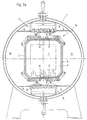
- the furnace system shown in Fig. 1 consists essentially of a furnace housing 1 and two hoods 2 which can be closed in a pressure-tight manner with this furnace housing 1, the left hood 2 serving to receive an electric drive (not shown) for a cooling gas blower 3.
- a heating chamber 6 surrounded by an outer chamber 4 and surrounded by heating chamber walls 5 is arranged within the furnace housing 1.
- heating elements are arranged in the heating chamber 6. The convection of the furnace atmosphere within the heating chamber 6 takes place in the case of convective heating via a fan 8.
- a gas cooling device 9 is arranged within the furnace housing 1 and consists of the cooling gas blower 3 and a heat exchanger 10.
- the outer chamber 4 surrounding the heating chamber 6 is designed as a pressure chamber connected to the pressure side of the cooling gas blower 3, while an inner chamber 11 formed between the heating chamber 6 and the gas cooling device 9 is designed as a suction chamber connected to the suction side of the cooling gas blower 3.
- the heating chamber walls 5 have openings 12 which connect to the pressure chamber 4 or the suction chamber 11 Hatches 13 can be opened and closed. These hatches 13 can be driven via hatch actuation 14, which is not described in detail.
- height-adjustable gas guiding devices 15 are arranged in the area of the openings 12 in the heating chamber walls 5.
- the gas guide devices 15 each consist of a support frame 16, in which interchangeable gas guide elements 17 can be used.
- the gas guiding devices 15 are arranged in the region of the openings 12 in such a way that, in the upper position lifted from the openings 12 (shown in FIG. 1 below), the pressure chamber 4 shuts off towards the heating chamber 6 and in the on the opening 12 lowered position (shown in Fig. 1 above) shuts off the suction chamber 11 to the heating chamber 6. Due to the fact that the gas guiding devices 15 in the upper position - shown in FIG. 2a - close the pressure chamber 4 towards the heating chamber 6, a dust pressure forms within the pressure chamber 4 when the cooling gas blower 3 is actuated. This dynamic pressure built up in the pressure chamber 4 can build up do not dismantle until a gas guide device 15 is lowered onto an opening 12, as shown in FIGS.
- the gas guide devices 15 are operated as follows during operation:
- the heating elements arranged in the heating chamber 6 are switched off and then the cooling gas blower 3 is switched on.
- the openings 12 in the heating chamber walls 5 are closed via the hatches 13 and the gas guide devices 15 are in the upper position which is lifted off the openings 12 and in which they connect shut off between the pressure chamber 4 and the heating chamber 6, as shown in Fig. 2a.
- the cooling gas blower By operating the cooling gas blower, a certain dynamic pressure of the cooling gas builds up in the pressure chamber 4.
- the hatches 13 are then opened via the hatch actuations 14, so that unhindered access to the heating chamber 6 is possible via the openings 12, as shown in FIG. 2b.
- a gas guiding device 15 is now lowered onto an opening 12, as illustrated in FIG. 2c.
- the access between the furnace chamber 6 and the suction chamber 11 is closed at the same time, so that the cooling gas accumulated in the pressure chamber 4 can only flow into the heating chamber 6.
- the gas guide elements 17 arranged in the gas guiding devices 15 are designed as plates 19 provided with nozzles 18.
- the use of nozzles 18 as gas guiding elements 17 is particularly advantageous, since this enables a targeted cooling gas flow onto the charge 7 that has a predeterminable penetration depth.
- the heating chamber 6 is flooded via the cooling gas flowing in from the pressure chamber 4.
- the hot furnace gas and the heated cooling gas are sucked out through the opposite opening 12 to the suction chamber 11, since on this side the gas guide device 15 is in the upper position, in which there is an unimpeded connection between the heating chamber 6 and the suction chamber 11.
- the cooling gas is cooled back via the heat exchanger 10 arranged in the gas cooling device 9 and reaches the heating chamber 6 again via the pressure chamber 4.
Applications Claiming Priority (2)
| Application Number | Priority Date | Filing Date | Title |
|---|---|---|---|
| DE19526676 | 1995-07-21 | ||
| DE19526676 | 1995-07-21 |
Publications (2)
| Publication Number | Publication Date |
|---|---|
| EP0754768A1 true EP0754768A1 (fr) | 1997-01-22 |
| EP0754768B1 EP0754768B1 (fr) | 2001-06-13 |
Family
ID=7767437
Family Applications (2)
| Application Number | Title | Priority Date | Filing Date |
|---|---|---|---|
| EP96710008A Withdrawn EP0754769A1 (fr) | 1995-07-21 | 1996-07-13 | Four pour le traitement thermique de charges de pièces métalliques |
| EP96710009A Expired - Lifetime EP0754768B1 (fr) | 1995-07-21 | 1996-07-13 | Four pour le traitement thermique de charges de pièces métalliques |
Family Applications Before (1)
| Application Number | Title | Priority Date | Filing Date |
|---|---|---|---|
| EP96710008A Withdrawn EP0754769A1 (fr) | 1995-07-21 | 1996-07-13 | Four pour le traitement thermique de charges de pièces métalliques |
Country Status (4)
| Country | Link |
|---|---|
| EP (2) | EP0754769A1 (fr) |
| AT (1) | ATE202152T1 (fr) |
| DE (2) | DE59607067D1 (fr) |
| ES (1) | ES2159710T3 (fr) |
Cited By (3)
| Publication number | Priority date | Publication date | Assignee | Title |
|---|---|---|---|---|
| FR2864106A1 (fr) * | 2003-12-23 | 2005-06-24 | Etudes Const Mecaniques | Dispositif de trempe |
| US8088328B2 (en) | 2008-06-13 | 2012-01-03 | Jones William R | Vacuum nitriding furnace |
| WO2017041774A1 (fr) * | 2015-09-09 | 2017-03-16 | Ipsen International Gmbh | Dispositif de traitement de pièces métalliques avec du gaz de refroidissement |
Families Citing this family (5)
| Publication number | Priority date | Publication date | Assignee | Title |
|---|---|---|---|---|
| DE19820083A1 (de) * | 1998-05-06 | 1999-11-11 | Ald Vacuum Techn Gmbh | Verfahren zum Abschrecken von Werkstücken und Wärmebehandlungsanlage zur Durchführung des Verfahrens |
| US6533991B1 (en) * | 2000-06-20 | 2003-03-18 | Ipsen International, Inc. | Cooling gas injection nozzle for a vacuum heat treating furnace |
| JP4573290B2 (ja) * | 2003-10-17 | 2010-11-04 | 株式会社Ihi | 高圧熱処理炉 |
| DE102009052900A1 (de) | 2009-11-13 | 2011-05-19 | Ipsen International Gmbh | Verfahren und Einrichtung zur Leitung der Strömumg in Industrieöfen für die Wärmebehandlung von metallischen Werkstoffen/Werkstücken |
| EP2622107A1 (fr) | 2010-09-24 | 2013-08-07 | Ipsen International GmbH | Procédé et dispositif destinés à guider un écoulement dans des fours industriels pour le traitement thermique de matériaux/pièces métalliques |
Citations (6)
| Publication number | Priority date | Publication date | Assignee | Title |
|---|---|---|---|---|
| DE3208574A1 (de) * | 1982-03-10 | 1983-09-22 | Schmetz Industrieofenbau und Vakuum-Hartlöttechnik KG, 5750 Menden | "vakuum-schachtofen" |
| DE3215509A1 (de) * | 1982-04-26 | 1983-10-27 | Schmetz Industrieofenbau und Vakuum-Hartlöttechnik KG, 5750 Menden | Vakuum-kammerofen |
| DE3321554C1 (de) * | 1982-07-16 | 1984-02-16 | Ipsen Industries International Gmbh, 4190 Kleve | Industrieofen zur Wärmebehandlung metallischer Werkstücke |
| GB2152199A (en) * | 1983-12-23 | 1985-07-31 | Ipsen Ind Int Gmbh | Industrial furnace |
| DE9311985U1 (de) * | 1993-08-11 | 1993-10-14 | Ipsen Ind Int Gmbh | Ofen zur Wärmebehandlung von Chargen metallischer Werkstücke |
| DE9400222U1 (de) * | 1994-01-08 | 1994-02-24 | Ipsen Ind Int Gmbh | Mehrkammerofen mit kombinierter Abkühlung |
Family Cites Families (2)
| Publication number | Priority date | Publication date | Assignee | Title |
|---|---|---|---|---|
| DE3224971A1 (de) * | 1982-07-03 | 1984-01-05 | Schmetz Industrieofenbau und Vakuum-Hartlöttechnik KG, 5750 Menden | Vakuum-schachtofen |
| FR2651307B1 (fr) * | 1989-08-29 | 1993-12-17 | Traitement Sous Vide | Four de traitement thermique equipe de moyens de refroidissement perfectionnes. |
-
1996
- 1996-07-13 ES ES96710009T patent/ES2159710T3/es not_active Expired - Lifetime
- 1996-07-13 EP EP96710008A patent/EP0754769A1/fr not_active Withdrawn
- 1996-07-13 AT AT96710009T patent/ATE202152T1/de not_active IP Right Cessation
- 1996-07-13 EP EP96710009A patent/EP0754768B1/fr not_active Expired - Lifetime
- 1996-07-13 DE DE59607067T patent/DE59607067D1/de not_active Expired - Fee Related
- 1996-07-13 DE DE1996128383 patent/DE19628383A1/de not_active Withdrawn
Patent Citations (6)
| Publication number | Priority date | Publication date | Assignee | Title |
|---|---|---|---|---|
| DE3208574A1 (de) * | 1982-03-10 | 1983-09-22 | Schmetz Industrieofenbau und Vakuum-Hartlöttechnik KG, 5750 Menden | "vakuum-schachtofen" |
| DE3215509A1 (de) * | 1982-04-26 | 1983-10-27 | Schmetz Industrieofenbau und Vakuum-Hartlöttechnik KG, 5750 Menden | Vakuum-kammerofen |
| DE3321554C1 (de) * | 1982-07-16 | 1984-02-16 | Ipsen Industries International Gmbh, 4190 Kleve | Industrieofen zur Wärmebehandlung metallischer Werkstücke |
| GB2152199A (en) * | 1983-12-23 | 1985-07-31 | Ipsen Ind Int Gmbh | Industrial furnace |
| DE9311985U1 (de) * | 1993-08-11 | 1993-10-14 | Ipsen Ind Int Gmbh | Ofen zur Wärmebehandlung von Chargen metallischer Werkstücke |
| DE9400222U1 (de) * | 1994-01-08 | 1994-02-24 | Ipsen Ind Int Gmbh | Mehrkammerofen mit kombinierter Abkühlung |
Cited By (4)
| Publication number | Priority date | Publication date | Assignee | Title |
|---|---|---|---|---|
| FR2864106A1 (fr) * | 2003-12-23 | 2005-06-24 | Etudes Const Mecaniques | Dispositif de trempe |
| US8088328B2 (en) | 2008-06-13 | 2012-01-03 | Jones William R | Vacuum nitriding furnace |
| WO2017041774A1 (fr) * | 2015-09-09 | 2017-03-16 | Ipsen International Gmbh | Dispositif de traitement de pièces métalliques avec du gaz de refroidissement |
| US10934599B2 (en) | 2015-09-09 | 2021-03-02 | Ipsen, Inc. | Device for treating metal workpieces with cooling gas |
Also Published As
| Publication number | Publication date |
|---|---|
| DE59607067D1 (de) | 2001-07-19 |
| ATE202152T1 (de) | 2001-06-15 |
| EP0754769A1 (fr) | 1997-01-22 |
| ES2159710T3 (es) | 2001-10-16 |
| EP0754768B1 (fr) | 2001-06-13 |
| DE19628383A1 (de) | 1997-02-06 |
Similar Documents
| Publication | Publication Date | Title |
|---|---|---|
| DE2844843C2 (de) | Industrieofen zur Wärmebehandlung metallischer Werkstücke | |
| EP0151700B1 (fr) | Four industriel, notamment four à vide à chambres multiples, pour le traitement thermique de charges de pièces métalliques | |
| DE3215509C2 (fr) | ||
| EP2312953B1 (fr) | Four boulangerie avec appareil à buées | |
| DE2637646A1 (de) | Anwaermofen | |
| EP3397782B1 (fr) | Dispositif de traitement de pièces métalliques avec du gaz de refroidissement | |
| EP0754768B1 (fr) | Four pour le traitement thermique de charges de pièces métalliques | |
| EP1154024B1 (fr) | Procédé et dispositif pour le traitement thermique de pièces métalliques | |
| DE10148548C5 (de) | Backofen | |
| DE10210952B4 (de) | Vorrichtung zur Behandlung von metallischen Werkstücken mit Kühlgas | |
| DE3224971C2 (fr) | ||
| EP2330325A2 (fr) | Four à cornue pour le traitement thermique de pièces usinées métalliques | |
| DE2501360B2 (de) | Vakuum-Atmosphärenofen zur Wärmebehandlung von Werkstücken | |
| DE3819803C1 (fr) | ||
| EP2622107A1 (fr) | Procédé et dispositif destinés à guider un écoulement dans des fours industriels pour le traitement thermique de matériaux/pièces métalliques | |
| EP0864519A1 (fr) | Dispositif pour guider une bande de façon flottante | |
| DE4034085C1 (fr) | ||
| DE19538364C5 (de) | Vorrichtung zur Schnellerwärmung von Metall-Preßbolzen | |
| DE705764C (de) | Durchziehschachtofen mit Waermerueckgewinnung | |
| DE3130064C2 (de) | Backofen | |
| DE3842372C2 (de) | Vorrichtung zur Wärmebehandlung metallischer Werkstücke | |
| DE202008011194U1 (de) | Retortenofen zur Wärmebehandlung von metallischen Werkstücken | |
| DE10038782C1 (de) | Verfahren und Vorrichtung zum Abkühlen, insbesondere zum Abschrecken und Härten von metallischen Werkstücken | |
| DE887357C (de) | Vorrichtung zum Betrieb eines Durchgangsofens mit Vorwaermkammer, Erhitzungskammer und Kuehlkammer | |
| DE10227498B4 (de) | Verfahren und Vorrichtung zur konvektiven Wärmeübertragung zwischen einem Wärmeübertragungsmittel und der Stirnfläche eines gewickelten Metallbandes in Form eines Coils |
Legal Events
| Date | Code | Title | Description |
|---|---|---|---|
| PUAI | Public reference made under article 153(3) epc to a published international application that has entered the european phase |
Free format text: ORIGINAL CODE: 0009012 |
|
| AK | Designated contracting states |
Kind code of ref document: A1 Designated state(s): AT CH DE ES FR GB IT LI |
|
| 17P | Request for examination filed |
Effective date: 19970109 |
|
| RAP1 | Party data changed (applicant data changed or rights of an application transferred) |
Owner name: IPSEN INTERNATIONAL GMBH |
|
| 17Q | First examination report despatched |
Effective date: 19991102 |
|
| GRAG | Despatch of communication of intention to grant |
Free format text: ORIGINAL CODE: EPIDOS AGRA |
|
| GRAG | Despatch of communication of intention to grant |
Free format text: ORIGINAL CODE: EPIDOS AGRA |
|
| GRAH | Despatch of communication of intention to grant a patent |
Free format text: ORIGINAL CODE: EPIDOS IGRA |
|
| GRAH | Despatch of communication of intention to grant a patent |
Free format text: ORIGINAL CODE: EPIDOS IGRA |
|
| GRAA | (expected) grant |
Free format text: ORIGINAL CODE: 0009210 |
|
| AK | Designated contracting states |
Kind code of ref document: B1 Designated state(s): AT CH DE ES FR GB IT LI |
|
| REF | Corresponds to: |
Ref document number: 202152 Country of ref document: AT Date of ref document: 20010615 Kind code of ref document: T |
|
| REG | Reference to a national code |
Ref country code: CH Ref legal event code: NV Representative=s name: E. BLUM & CO. PATENTANWAELTE * E. BLUM & CO. PATEN |
|
| ET | Fr: translation filed | ||
| REF | Corresponds to: |
Ref document number: 59607067 Country of ref document: DE Date of ref document: 20010719 |
|
| ITF | It: translation for a ep patent filed |
Owner name: ING. ZINI MARANESI & C. S.R.L. |
|
| GBT | Gb: translation of ep patent filed (gb section 77(6)(a)/1977) |
Effective date: 20010817 |
|
| REG | Reference to a national code |
Ref country code: ES Ref legal event code: FG2A Ref document number: 2159710 Country of ref document: ES Kind code of ref document: T3 |
|
| REG | Reference to a national code |
Ref country code: GB Ref legal event code: IF02 |
|
| PLBE | No opposition filed within time limit |
Free format text: ORIGINAL CODE: 0009261 |
|
| STAA | Information on the status of an ep patent application or granted ep patent |
Free format text: STATUS: NO OPPOSITION FILED WITHIN TIME LIMIT |
|
| 26N | No opposition filed | ||
| PGFP | Annual fee paid to national office [announced via postgrant information from national office to epo] |
Ref country code: GB Payment date: 20030704 Year of fee payment: 8 |
|
| PGFP | Annual fee paid to national office [announced via postgrant information from national office to epo] |
Ref country code: CH Payment date: 20030708 Year of fee payment: 8 |
|
| PGFP | Annual fee paid to national office [announced via postgrant information from national office to epo] |
Ref country code: ES Payment date: 20030718 Year of fee payment: 8 |
|
| PG25 | Lapsed in a contracting state [announced via postgrant information from national office to epo] |
Ref country code: GB Free format text: LAPSE BECAUSE OF NON-PAYMENT OF DUE FEES Effective date: 20040713 |
|
| PG25 | Lapsed in a contracting state [announced via postgrant information from national office to epo] |
Ref country code: ES Free format text: LAPSE BECAUSE OF NON-PAYMENT OF DUE FEES Effective date: 20040714 |
|
| PG25 | Lapsed in a contracting state [announced via postgrant information from national office to epo] |
Ref country code: LI Free format text: LAPSE BECAUSE OF NON-PAYMENT OF DUE FEES Effective date: 20040731 Ref country code: CH Free format text: LAPSE BECAUSE OF NON-PAYMENT OF DUE FEES Effective date: 20040731 |
|
| GBPC | Gb: european patent ceased through non-payment of renewal fee |
Effective date: 20040713 |
|
| REG | Reference to a national code |
Ref country code: CH Ref legal event code: PL |
|
| PGFP | Annual fee paid to national office [announced via postgrant information from national office to epo] |
Ref country code: AT Payment date: 20050628 Year of fee payment: 10 |
|
| PGFP | Annual fee paid to national office [announced via postgrant information from national office to epo] |
Ref country code: FR Payment date: 20050712 Year of fee payment: 10 |
|
| PG25 | Lapsed in a contracting state [announced via postgrant information from national office to epo] |
Ref country code: IT Free format text: LAPSE BECAUSE OF NON-PAYMENT OF DUE FEES Effective date: 20050713 |
|
| REG | Reference to a national code |
Ref country code: ES Ref legal event code: FD2A Effective date: 20040714 |
|
| PG25 | Lapsed in a contracting state [announced via postgrant information from national office to epo] |
Ref country code: AT Free format text: LAPSE BECAUSE OF NON-PAYMENT OF DUE FEES Effective date: 20060713 |
|
| REG | Reference to a national code |
Ref country code: FR Ref legal event code: ST Effective date: 20070330 |
|
| PGFP | Annual fee paid to national office [announced via postgrant information from national office to epo] |
Ref country code: DE Payment date: 20070816 Year of fee payment: 12 |
|
| PG25 | Lapsed in a contracting state [announced via postgrant information from national office to epo] |
Ref country code: FR Free format text: LAPSE BECAUSE OF NON-PAYMENT OF DUE FEES Effective date: 20060731 |
|
| PG25 | Lapsed in a contracting state [announced via postgrant information from national office to epo] |
Ref country code: DE Free format text: LAPSE BECAUSE OF NON-PAYMENT OF DUE FEES Effective date: 20090203 |