EP0753809B1 - Construction compacte d'une alimentation électrique pour ordinateur portatif - Google Patents
Construction compacte d'une alimentation électrique pour ordinateur portatif Download PDFInfo
- Publication number
- EP0753809B1 EP0753809B1 EP96304652A EP96304652A EP0753809B1 EP 0753809 B1 EP0753809 B1 EP 0753809B1 EP 96304652 A EP96304652 A EP 96304652A EP 96304652 A EP96304652 A EP 96304652A EP 0753809 B1 EP0753809 B1 EP 0753809B1
- Authority
- EP
- European Patent Office
- Prior art keywords
- module
- power supply
- heat
- circuit board
- electromagnetic shield
- Prior art date
- Legal status (The legal status is an assumption and is not a legal conclusion. Google has not performed a legal analysis and makes no representation as to the accuracy of the status listed.)
- Expired - Lifetime
Links
Images
Classifications
-
- G—PHYSICS
- G06—COMPUTING; CALCULATING OR COUNTING
- G06F—ELECTRIC DIGITAL DATA PROCESSING
- G06F1/00—Details not covered by groups G06F3/00 - G06F13/00 and G06F21/00
- G06F1/16—Constructional details or arrangements
- G06F1/1613—Constructional details or arrangements for portable computers
- G06F1/1615—Constructional details or arrangements for portable computers with several enclosures having relative motions, each enclosure supporting at least one I/O or computing function
- G06F1/1616—Constructional details or arrangements for portable computers with several enclosures having relative motions, each enclosure supporting at least one I/O or computing function with folding flat displays, e.g. laptop computers or notebooks having a clamshell configuration, with body parts pivoting to an open position around an axis parallel to the plane they define in closed position
-
- G—PHYSICS
- G06—COMPUTING; CALCULATING OR COUNTING
- G06F—ELECTRIC DIGITAL DATA PROCESSING
- G06F1/00—Details not covered by groups G06F3/00 - G06F13/00 and G06F21/00
- G06F1/16—Constructional details or arrangements
- G06F1/1613—Constructional details or arrangements for portable computers
- G06F1/1633—Constructional details or arrangements of portable computers not specific to the type of enclosures covered by groups G06F1/1615 - G06F1/1626
- G06F1/1635—Details related to the integration of battery packs and other power supplies such as fuel cells or integrated AC adapter
-
- G—PHYSICS
- G06—COMPUTING; CALCULATING OR COUNTING
- G06F—ELECTRIC DIGITAL DATA PROCESSING
- G06F1/00—Details not covered by groups G06F3/00 - G06F13/00 and G06F21/00
- G06F1/16—Constructional details or arrangements
- G06F1/1613—Constructional details or arrangements for portable computers
- G06F1/1633—Constructional details or arrangements of portable computers not specific to the type of enclosures covered by groups G06F1/1615 - G06F1/1626
- G06F1/1656—Details related to functional adaptations of the enclosure, e.g. to provide protection against EMI, shock, water, or to host detachable peripherals like a mouse or removable expansions units like PCMCIA cards, or to provide access to internal components for maintenance or to removable storage supports like CDs or DVDs, or to mechanically mount accessories
- G06F1/1658—Details related to functional adaptations of the enclosure, e.g. to provide protection against EMI, shock, water, or to host detachable peripherals like a mouse or removable expansions units like PCMCIA cards, or to provide access to internal components for maintenance or to removable storage supports like CDs or DVDs, or to mechanically mount accessories related to the mounting of internal components, e.g. disc drive or any other functional module
-
- G—PHYSICS
- G06—COMPUTING; CALCULATING OR COUNTING
- G06F—ELECTRIC DIGITAL DATA PROCESSING
- G06F1/00—Details not covered by groups G06F3/00 - G06F13/00 and G06F21/00
- G06F1/16—Constructional details or arrangements
- G06F1/18—Packaging or power distribution
- G06F1/181—Enclosures
- G06F1/182—Enclosures with special features, e.g. for use in industrial environments; grounding or shielding against radio frequency interference [RFI] or electromagnetical interference [EMI]
-
- G—PHYSICS
- G06—COMPUTING; CALCULATING OR COUNTING
- G06F—ELECTRIC DIGITAL DATA PROCESSING
- G06F1/00—Details not covered by groups G06F3/00 - G06F13/00 and G06F21/00
- G06F1/16—Constructional details or arrangements
- G06F1/20—Cooling means
- G06F1/203—Cooling means for portable computers, e.g. for laptops
Definitions
- the present invention is directed, in general, to power supplies and, more specifically, to a power supply embodying a volume-efficient construction allowing the power supply to fit within the chassis of a portable computer system.
- Portable, battery-powered computers have become increasingly popular over the last several years due to their light weight and small size that permit them to be easily hand-carried in an ordinary briefcase and used by business travelers in cramped spaces, such as on airline seat back trays, lacking electrical plug-in facilities.
- a particularly small type of portable computer, the notebook computer is very popular, generally having dimensions of 8.5" x 11" and a weight of less than 8 pounds. More recent developments in computer miniaturization have resulted in so-called "subnotebook" computers having still smaller dimensions.
- the modern portable computer typically incorporates both hard and floppy disk drives, a display screen built into a pivoting display screen portion, and a keyboard built into a main chassis portion. It is thus a fully self-contained computer able to be conventionally used, for at least short periods of time, in situations' and locations in which the use of a much larger desktop computer is simply not feasible.
- prior art separate supplies have been comparatively large and over-engineered. Heat-producing components in such supplies are most often cooled by mounting heat sinks to each component. The fins or projections of the heat sinks are bulky and heavy. The power supplies are surrounded by an electromagnetic interference (“EMI”) shield to attenuate and guard against stray EMI.
- EMI electromagnetic interference
- the prior art power supply chassis housing these power supplies and their associated shields have been correspondingly large, heavy and cumbersome, earning them the unflattering colloquial term "brick.”
- Document JP-A-07 093 065 discloses a computer power supply which is mounted an a portable computer 10 that at least two surfaces are exposed.
- the present invention provides a power supply module for a portable computer and a method of dissipating heat generated in the power supply module.
- the module comprises: (1) a circuit board having a plurality of power supply components mounted thereon, (2) a module electromagnetic shield at least partially surrounding the circuit board, the module electromagnetic shield electromagnetically shielding at least some of the plurality of power supply components, (3) metallic heat conduction paths, integrally disposed within the circuit board and substantially within a footprint of selected ones of the plurality of power supply components, for transferring heat from the selected ones of the plurality of power supply components through the circuit board and (4) compliant heat conduction pads, coupled between the circuit board and the module electromagnetic shield, for transferring the heat from the heat conduction paths to the module electromagnetic shield, the module electromagnetic shield dissipating the heat and thereby functioning as a heat sink, the heat conduction paths and heat conduction pads cooperating to form a compact structure for transferring heat from the selected ones of the plurality of power supply components to thereby reduce a required volume
- the present invention introduces a novel heat transfer route from the components of the power supply.
- the path liberates heat by collecting heat from an underside of the selected components, transferring the heat through the circuit board to an underside thereof, transferring the heat through compliant heat-conductive pads located under the circuit board to the surrounding electromagnetic shield and dissipating the heat in the shield.
- This new path allows prior art heat sinks (mounted over the components) to be eliminated, 'thereby decreasing the dimensions and volume of the module and rendering it suitable for integral inclusion within the portable computer.
- the heat conduction paths comprise heat-conductive metallic pads positioned on opposing sides of the circuit board that are in conductive contact with metal-sleeved vias extending through the circuit board.
- Metal-sleeved vias have long been employed to carry electrical current among various circuit board layers. However, such vias have not to-date been employed to advantage as heat conduits.
- the present invention therefore can use conventional circuit board production techniques to form heat conduction paths. Those of ordinary skill in the art will recognize that placement of other media of high thermal conductivity within the circuit board, such as embedded metal posts, is within the scope of the present invention.
- the heat conduction pads comprise thermally transmissive foam and at least partially mechanically mount the circuit board to the module electromagnetic shield.
- foam is commercially available, e.g., under the trade-name ChothermTM and the physical properties of such are well known. However, it is new to employ foam as heat conduction pads under the circuit board.
- the module is a switching power supply, the selected ones of the plurality of power supply components being switching devices.
- switching power supplies are in wide use with portable computers. However, such power supplies suffer from high heat output by the switching devices therein.
- the present invention is particularly advantageous at removing heat generated in the switching devices in switching-type power supplies.
- the module further comprises a line power input adapted to receive line power from an external source, the line power being at least 100 volts.
- a line power input adapted to receive line power from an external source, the line power being at least 100 volts.
- the module of the present invention is adapted to receive unconverted electrical power directly from a line power source, such as ubiquitous wall outlets.
- the module is associated with a line cord having a plug end and an outlet end and adapted to deliver electrical power of at least 100 volts and at least 50 cycles per second from a power source (such as the wall outlet) coupled to the plug end to the power supply via the outlet end without power conversion.
- a power source such as the wall outlet
- the module electromagnetic shield has mounts integral therewith to allow the module electromagnetic shield to be secured within a main chassis of the portable computer. Unlike the electromagnetic shield in a "brick," 'the electromagnetic shield of the present invention must adapt to the confines of a portable computer chassis. Accordingly, the module electromagnetic shield is provided with mounts to allow it to be secured to surrounding chassis walls and other modules.
- the module further comprises a motherboard connector allowing the module to be connected directly to a motherboard of the portable computer. Because the module of the present invention is integral with the main chassis, the prior art external connector between the power supply and the motherboard is no longer needed. Accordingly, the module has a direct motherboard connection associated therewith.
- the selected ones of the plurality of power supply components have multiple heat conduction paths associated therewith.
- the present invention allows the number of heat conduction paths to be selected so that the associated power supply component remains within its standard operating temperature range, neither undercooled nor overcooled.
- the module electromagnetic shield only partially surrounds the circuit board, a portion of the circuit board thereby exposed to an environment surrounding the module, the module electromagnetic shield cooperating with a main chassis electromagnetic shield of the portable computer to form an electromagnetic enclosure completely surrounding the circuit board when the module is secured within the main chassis electromagnetic shield.
- the present invention realizes further gains in miniaturization of the power supply module by allowing the main chassis electromagnetic shield to form a portion of the overall shield for the power supply module. This is a significant preferred embodiment, as reductions of even fractions of an inch are valuable when adapting a power supply module to fit within the main chassis of a portable computer. Instead of simply providing overlapping module and main chassis electromagnetic shields, one thickness of the module electromagnetic shield is eliminated, further reducing module dimensions and volume.
- the portable computer is a portable PC.
- portable PC Those of skill in the art will readily find application for the present invention in all kinds of portable electrical devices that once required separate power supplies. Thus, the present invention is not limited to application in portable PCs.
- the present invention yields a portable PC, comprising: (1) a main chassis hingedly coupled to a display screen chassis to allow the portable PC to assume alternative stowed and deployed positions, (2) a display screen associated with the display screen chassis, (3) an input device and an externally-accessible storage device associated with the main chassis and (4) a motherboard and a plurality of modules contained within the main chassis, one of the plurality of modules being a power supply module as previously described.
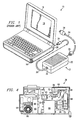
- FIG. 1 illustrated is an isometric view of a prior art portable computer 10 and an associated power supply "brick" 12 that is exterior to the prior art portable computer 10.
- the brick 12 is designed to convert alternating current (“AC") power to a form usable by the prior art portable computer 10.
- AC alternating current
- portable computers are typically designed to run on direct current (“DC”), which is usually supplied by an internal DC battery (not shown).
- DC direct current
- the DC battery is recharged by the user plugging the power supply brick 12 into a conventional AC outlet that supplies the AC, which is converted into DC by the power supply brick 12.
- direct DC operational power may be supplied to the prior art portable computer 10 from the AC source via the power supply brick 12.
- the prior art portable computer 10 has a base member 14 and a lid member 16 with a screen portion 18 therein.
- the base member 14 is comprised of a computer base housing 20 that houses the internal electrical components of the prior art portable computer 10.
- the power supply brick 12 has a brick housing 22 that surrounds and houses the internal electrical components of the power supply brick 12, which convert the electrical power from AC to direct current DC.
- a distinct disadvantage associated with the conventional power supply brick 12 is that it has an overall height or thickness that exceeds the overall thickness of the computer base housing 20. Thus, it must be carried and used externally from the computer base housing 20. Additionally, the weight of the power supply brick 12 adds substantially to the total weight associated with the prior art portable computer 10.
- the power supply brick 12 is also cumbersome to use and store because of the line cords associated with it.
- the power supply brick 12 has two electrical line cords associated with it, an AC cord 24 and a DC cord 26, both of which are individually connectable to the power supply brick 12.
- the AC cord 24 has a first end 28 that is designed to be electrically connected to an AC power supply (not shown) and a second end 30 that is designed to be electrically connected to the power supply brick 12.
- the DC cord 26 has a first end 32 that is designed to be electrically connected to the power supply brick 12 and a second end 34 that is designed to be electrically connected to the prior art portable computer 10. From these disadvantages, it is clear that a need has arisen for a portable computer with a light-weight, heat dissipating adapter that can fit within the chassis of the portable computer.
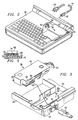
- FIG. 2 in a preferred embodiment thereof, illustrated is a partially cut-away isometric view of a portable computer chassis 36 having a built-in power supply module 38 embodying the construction of the present invention.
- the portable computer chassis 36 is generally of conventional design with the exception that it is designed to completely contain the miniaturized power supply module 38 within the portable computer chassis 36.
- the power supply module 38 has mounts 40 integral therewith so that it may be secured within the portable computer chassis 36.
- the power supply module 38 is at least partially surrounded by a module electromagnetic shield 42.
- the power supply module 38 is extremely light-weight and has a miniaturized size and construction that allows it to be completely contained within the portable computer chassis 36.
- the power supply module 38 is secured within the portable computer chassis 36, the user does not have to handle a heavy, cumbersome brick with it plurality of cords, but can instead, fully utilize the power supply module 38 simply by plugging a cord into it and an appropriate power source.
- a single line power cord 44 that has a first end 46 designed to be electrically connected to a conventional external power supply outlet of at least 100 volts and at least 50 cycles, and a second end 48 designed to be connected directly to a line power input 50 of the power supply module 38.
- the line power cord 44 is, an electrical cord that is adapted to be connected to conventional outlets found throughout most nations in the world. More preferably, however, the line power cord 44 is adapted to be connected to a 110 volt, 60 cycle outlet.
- the power supply module 38 also preferably includes a motherboard connector 52 that enables the power supply module 38 to be removably connected directly to a motherboard 54 positioned within the portable computer chassis 36.
- FIG. 3 illustrated is a rearside isometric view of the portable computer chassis 36 of FIG. 2 with the power supply module exploded therefrom for clarity.
- the module electromagnetic shield 42 of the power supply module 38 is clearly illustrated.
- the module electromagnetic shield 42 partially surrounds a circuit board (not shown) of the power supply module 38.
- the module electromagnetic shield 42 cooperates with a main chassis electromagnetic shield 56 of the portable computer chassis 36 to form an electromagnetic enclosure around the power supply module's 38 circuit board when the power supply module 38 is secured within the main chassis electromagnetic shield 56. While the embodiment illustrated shows the module electromagnetic shield 42 only partially surrounding the power supply components, it will be appreciated that the module electromagnetic shield 42 could be made to completely surround the power supply components.
- the line power input 50 Positioned on a rear end portion 58 of the power supply module 38 is the line power input 50 that is adapted to receive electrical power directly from an external source via the line power cord 44.
- the line power input 50 preferably has a projecting retaining shell 60 that is designed to frictionally engage and hold the second end 48 of the line power cord 44.
- the shell 60 is also designed to extend through aperture 62 formed in a side wall 64 of the portable computer chassis 36, thereby providing easy accessibility to connect the line power cord 44 to the power supply module 38.
- the power supply module 38 may be positioned in the portable computer chassis 36 by tilting the rear end portion 58 in a downwardly fashion and positioning the projecting retaining shell 60 through the aperture 62.
- FIG. 4 illustrated is a plan view of the power supply module of FIG. 3.
- the term power supply components means any electrical component that is used directly, or indirectly to supply power to an electronic device. The remaining power supply components are hidden from view by a plastic shield.
- the power supply module 38 is a switching power supply module wherein selected ones of the plurality of the power supply components 66 are switching devices, such as transistors. More preferably, however, the switching power supply module 38 is an AC adapter wherein AC is converted to DC, a form of electrical power that can be used by the portable computer.
- the power supply components 66 of the power supply module 38 particularly components such as transistors, generate significant amounts of heat that require dissipation to prevent harmful buildup of heat within the portable computer chassis 36.
- dissipation of heat was not of paramount importance because the brick was located outside the chassis, but this still required heat production devices to be attached to large heat sink devices, which also contributed to the brick device's large size.
- heat dissipation can be a significant problem.
- the present invention also includes metallic heat conduction paths 70 integrally disposed within the circuit board 68 of the power supply module 38 for transferring heat from the power supply components 66 through;the circuit board 68 and to the module electromagnetic shield 42.
- the metallic heat conduction paths 70 are disposed substantially within a footprint of the power supply components 66. Coupled between the circuit board 68 and the module electromagnetic shield 42 are compliant heat conduction pads 72.
- the heat conduction pads 72 transfer the heat from the heat conduction paths 70 to the module electromagnetic shield 42, which then dissipates the heat over a wider surface area.
- the metallic heat conduction paths 70 cooperating with the heat conduction pads 72 and the electromagnetic shield function to form a compact heat sink structure for transferring heat from the power supply components 66.
- multiple heat conduction paths 70 may be associate with each of the power supply components 66, if so desired.
- FIG. 5 illustrated is a sectional view of a heat dissipation structure within the power supply module of FIG. 4, taken along lines 5-5.
- the power supply component 66 from which heat dissipation is required, is positioned on a heat-conductive metallic pad 76.
- the metallic pad 76 is a copper trace formed on the circuit board 68 and is integrally connected to the metal-sleeved via 74.
- the metallic pad 76 also covers the footprint of the power supply component 66.
- the metallic pad 76 covers the heat conduction path 70. Heat is conducted from the power supply component 66 by the metallic pad 76 and is then conducted from the metallic pad 76 via the heat conduction path 70.
- the heat conduction paths 70 are preferably comprised of heat-conductive, metal-sleeved vias 74 that extend through the circuit board 68, which are overlaid by the metallic pad 76. Positioned on the opposite side of and in contact with the circuit board 68 and the metal-sleeved via 74 is another heat-conductive metallic pad 78.
- the heat-conductive pad 78 is also preferably a copper trace formed on the printed circuit board 68 and is integrally formed with the metal-sleeved via. overlaying the entire footprint of the metallic pad 78 is the heat conduction pad 72 that is preferably comprised of a thermally transmissive foam.
- the metallic pad 76 conducts the heat from the power supply component to the via 74, which then conducts the heat from the metallic pad 76 to the metallic pad 78. The heat is then conducted from the metallic pad 78 to the heat conduction pad 72.
- the heat conduction pad 72 is in contact with the module electromagnetic shield 42, which conducts the heat away from the heat conduction pad 72.
- the heat conduction pad 72 has adhesive on its sides that contact the circuit board 68 and the module electromagnetic shield 42, which not only help holds the thermally transmissive foam in place, but also partially mechanically mounts the circuit board 68 to the module electromagnetic shield 42.
- the heat conduction pad 72 has an inherent adhesive property that does not require the application of adhesive to the heat conduction pad 72.
- heat conduction paths 70 and corresponding heat conduction pads 72 may be associated with each heat generating power supply component 66, it is preferable that they each be associated with the power supply components 66 that conduct the most heat.
- heat producing devices include switching devices, which are also surface mounted to optimize further heat transfer therefrom.
- the present invention provides a power supply module for a portable computer and a method of dissipating heat generated in the power supply module.
- the module comprises: (1) a circuit board having a plurality of power supply components mounted thereon, (2) a module electromagnetic shield at least partially surrounding the circuit board, the module electromagnetic shield electromagnetically shielding at least some of the plurality of power supply components, (3) metallic heat conduction paths, integrally disposed within the circuit board and substantially within a footprint of selected ones of the plurality of power supply components; for transferring heat from the selected ones of the plurality of power supply components through the circuit board and (4) compliant heat conduction pads, coupled between the circuit board and the module electromagnetic shield, for transferring the heat from the heat conduction paths to the module electromagnetic shield, the module electromagnetic shield dissipating the heat and thereby functioning as a heat sink, the heat conduction paths and heat conduction pads cooperating to form a compact structure for transferring heat from the selected ones of the plurality of power supply components to thereby reduce a required volume of the power supply
Landscapes
- Engineering & Computer Science (AREA)
- Theoretical Computer Science (AREA)
- Computer Hardware Design (AREA)
- Physics & Mathematics (AREA)
- General Engineering & Computer Science (AREA)
- Human Computer Interaction (AREA)
- General Physics & Mathematics (AREA)
- Power Engineering (AREA)
- Mathematical Physics (AREA)
- Electromagnetism (AREA)
- Shielding Devices Or Components To Electric Or Magnetic Fields (AREA)
Claims (26)
- Un module d'alimentation pour un ordinateur portable, comprenant :une carte de circuit sur laquelle une multiplicité de composants d'alimentation sont montés;un blindage électromagnétique de module entourant au moins partiellement la carte de circuit, ce blindage électromagnétique de module blindant au point de vue électromagnétique certains au moins de la multiplicité de composants d'alimentation;un chemin de conduction de chaleur, disposé d'une manière intégrée à la carte de circuit et pratiquement à l'intérieur de l'étendue occupée sur la carte par l'un sélectionné de la multiplicité de composants d'alimentation, pour transférer de la chaleur à partir de ce composant sélectionné parmi la multiplicité de composants d'alimentation, à travers la carte de circuit; etun tampon de conduction de chaleur déformable, couplé entre la carte de circuit et le blindage électromagnétique de module, pour transférer la chaleur à partir du chemin de conduction de chaleur vers le blindage électromagnétique de module, le blindage électromagnétique de module dissipant cette chaleur et fonctionnant ainsi comme un radiateur thermique, le chemin de conduction de chaleur et le tampon de conduction de chaleur coopérant pour former une structure compacte pour transférer de la chaleur à partir du composant sélectionné de la multiplicité de composants d'alimentation, pour réduire ainsi un volume exigé du module d'alimentation.
- Le module selon la revendication 1, dans lequel le chemin de conduction de chaleur comprend une plage métallique conductrice de la chaleur positionnée entre la carte de circuit et le composant sélectionné de la multiplicité de composants d'alimentation, pratiquement à l'intérieur d'une étendue occupée sur la carte par le composant sélectionné de la multiplicité de composants d'alimentation, et comprenant en outre un passage muni d'une douille métallique s'étendant à travers la carte de circuit, en contact physique avec la plage métallique conductrice de la chaleur.
- Le module selon la revendication 1, dans lequel les tampons de conduction de chaleur comprennent une mousse ayant une propriété de transmission thermique, et ils assurent au moins partiellement le montage mécanique de la carte de circuit sur le blindage électromagnétique de module.
- Le module selon la revendication 1, dans lequel le module est une alimentation à découpage, les composants sélectionnés de la multiplicité de composants d'alimentation étant des dispositifs de commutation.
- Le module selon la revendication 1, comprenant en outre une multiplicité de chemins de conduction de chaleur disposés de manière intégrée dans la carte de circuit, et pratiquement à l'intérieur d'étendues occupées sur la carte par des composants sélectionnés de la multiplicité de composants d'alimentation.
- Le module selon la revendication 1, comprenant en outre un connecteur de carte mère permettant de connecter directement le module à une carte mère de l'ordinateur portable.
- Le module selon la revendication 1, dans lequel les composants sélectionnés de la multiplicité de composants d'alimentation sont associés à de multiples chemins de conduction de chaleur.
- Le module selon la revendication 1, dans lequel le blindage électromagnétique de module entoure seulement partiellement la carte de circuit, une partie de cette carte de circuit est ainsi exposée à un environnement entourant le module, le blindage électromagnétique de module coopérant avec un blindage électromagnétique de châssis principal de l'ordinateur portable pour former une enceinte électromagnétique entourant complètement la carte de circuit, lorsque le module est fixé à l'intérieur du blindage électromagnétique de châssis principal.
- Le module selon la revendication 1, dans lequel le chemin de conduction de chaleur comprend une plage métallique conductrice de la chaleur positionnée entre la carte de circuit et le tampon de conduction de chaleur déformable, pratiquement à l'intérieur d'une étendue occupée sur la carte par le tampon de conduction de chaleur déformable, et comprenant en outre un passage muni d'une douille métallique s'étendant à travers la carte de circuit, en contact physique avec la plage métallique conductrice de la chaleur.
- Un procédé de dissipation de la chaleur générée dans un module d'alimentation pour un ordinateur portable, ce module incluant une carte de circuit sur laquelle une multiplicité de composants d'alimentation sont montés, et un blindage électromagnétique de module entourant au moins partiellement la carte de circuit, ce blindage électromagnétique de module blindant au point de vue électromagnétique certains au moins de la multiplicité de composants d'alimentation, ce procédé comprenant les étapes suivantes :on transfère initialement de la chaleur à partir des composants sélectionnés de la multiplicité de composants d'alimentation, à travers des chemins de conduction de chaleur métalliques disposés de manière intégrée à l'intérieur de la carte de circuit, et pratiquement à l'intérieur d'une étendue occupée sur la carte par des composants sélectionnés de la multiplicité de composants d'alimentation; eton transfère ensuite la chaleur à partir des chemins de conduction de chaleur vers le blindage électromagnétique de module, par l'intermédiaire de tampons de conduction de chaleur déformables, couplés entre la carte de circuit et le blindage électromagnétique de module, le blindage électromagnétique de module dissipant la chaleur et fonctionnant ainsi comme un radiateur thermique, les chemins de conduction de chaleur et les tampons de conduction de chaleur coopérant pour former une structure compacte pour transférer de la chaleur à partir des composants sélectionnés de la multiplicité de composants d'alimentation, pour réduire ainsi un volume exigé du module d'alimentation.
- Le procédé selon la revendication 10, dans lequel l'étape consistant à transférer initialement de la chaleur comprend les étapes consistant à transférer initialement la chaleur à partir des composants sélectionnés de la multiplicité de composants d'alimentation, vers des plages métalliques conductrices de la chaleur en contact physique avec les composants sélectionnés de la multiplicité de composants d'alimentation, et pratiquement à l'intérieur de l'étendue occupée sur la carte par ces composants sélectionnés, et à transférer la chaleur à partir des plages métalliques conductrices de la chaleur à travers des passages munis de douilles métalliques s'étendant à travers la carte de circuit.
- Le procédé selon la revendication 10, dans lequel l'étape consistant à transférer ensuite de la chaleur comprend l'étape consistant à transférer ensuite la chaleur à travers la mousse ayant une propriété de transmission thermique, les tampons de conduction de chaleur assurant au moins partiellement le montage mécanique de la carte de circuit sur le blindage électromagnétique de module.
- Le procédé selon la revendication 10, comprenant en outre l'étape consistant à fixer le blindage électromagnétique de module à l'intérieur d'un châssis principal de l'ordinateur portable, avec des éléments de montage intégrés au blindage électromagnétique de module.
- Le procédé selon la revendication 10, dans lequel l'étape consistant à transférer initialement de la chaleur comprend l'étape consistant à transférer initialement la chaleur par les multiples chemins de conduction de chaleur associés aux composants sélectionnés de la multiplicité de composants d'alimentation.
- Le procédé selon la revendication 10, dans lequel le blindage électromagnétique de module entoure seulement partiellement la carte de circuit, une partie de la carte de circuit étant ainsi exposée à un environnement entourant le module, ce procédé comprenant en outre l'étape consistant à enfermer la carte de circuit, au point de vue électromagnétique, lorsque le module est fixé à l'intérieur d'un blindage électromagnétique de châssis principal de l'ordinateur portable, le blindage électromagnétique de module coopérant avec le blindage électromagnétique de châssis principal pour former une enceinte électromagnétique.
- Le procédé selon la revendication 10, dans lequel l'étape consistant à transférer ensuite de la chaleur à partir des chemins de conduction de chaleur comprend les étapes consistant à transférer la chaleur à partir de passages munis de douilles métalliques, vers des plages métalliques conductrices de la chaleur en contact physique avec les passages munis de douilles métalliques, et positionnées entre ces passages et les tampons de conduction de chaleur déformables, et à transférer la chaleur à partir des tampons de conduction de chaleur vers le blindage électromagnétique de module.
- Un module d'alimentation à découpage pour un ordinateur personnel (PC) portable, comprenant :une carte de circuit sur laquelle une multiplicité de dispositifs de commutation d'alimentation sont montés;un blindage électromagnétique de module entourant au moins partiellement la carte de circuit, ce blindage électromagnétique de module blindant au point de vue électromagnétique certains au moins de la multiplicité de dispositifs de commutation d'alimentation, le blindage électromagnétique de module ayant des éléments de montage qui lui sont intégrés pour permettre au blindage électromagnétique de module d'être fixé à l'intérieur d'un châssis principal de l'ordinateur personnel portable;des passages munis de douilles métalliques s'étendant à travers la carte de circuit et disposés pratiquement à l'intérieur d'une étendue occupée sur la carte par des dispositifs sélectionnés de la multiplicité de dispositifs de commutation d'alimentation, pour transférer de la chaleur à partir des dispositifs sélectionnés de la multiplicité de dispositifs de commutation d'alimentation, à travers la carte de circuit;une mousse ayant une propriété de transmission thermique, couplée entre la carte de circuit et le blindage électromagnétique de module, pour transférer la chaleur à travers les passages munis de douilles métalliques vers le blindage électromagnétique de module, ce blindage électromagnétique de module dissipant la chaleur et fonctionnant ainsi comme un radiateur thermique; etdes plages métalliques conductrices de la chaleur couplées à la carte de circuit, pratiquement à l'intérieur d'une étendue occupée sur la carte par les dispositifs de commutation d'alimentation et la mousse ayant une propriété de transmission thermique, ces plages métalliques conductrices de la chaleur étant en contact physique avec les passages munis de douilles métalliques, les plages métalliques conductrices de la chaleur, les passages munis de douilles métalliques et la mousse ayant une propriété de transmission thermique coopérant pour former une structure compacte pour transférer de la chaleur à partir des dispositifs sélectionnés parmi la multiplicité de dispositifs de commutation d'alimentation, pour réduire ainsi un volume exigé du module d'alimentation.
- Le module selon la revendication 17, dans lequel la mousse ayant une propriété de transmission thermique assure au moins partiellement le montage mécanique de la carte de circuit sur le blindage électromagnétique de module.
- Le module selon la revendication 18, dans lequel les dispositifs sélectionnés de la multiplicité de dispositifs de commutation d'alimentation sont associés à de multiples exemplaires des passages munis de douilles métalliques.
- Le module selon la revendication 19, dans lequel le blindage électromagnétique de module entoure seulement partiellement la carte de circuit, une partie de la carte de circuit étant ainsi exposée à un environnement entourant le module, le blindage électromagnétique de module coopérant avec un blindage électromagnétique de châssis principal de l'ordinateur personnel portable pour former une enceinte électromagnétique entourant complètement la carte de circuit, lorsque le module est fixé à l'intérieur du blindage électromagnétique de châssis principal.
- Le module selon la revendication 20, comprenant en outre des plages métalliques conductrices de la chaleur couplées à la carte de circuit et pratiquement à l'intérieur de chacune des étendues occupées sur la carte par les dispositifs sélectionnés de la multiplicité de dispositifs de commutation d'alimentation, les plages métalliques conductrices de la chaleur étant positionnées entre la carte de circuit et chacun des dispositifs sélectionnés de la multiplicité de dispositifs de commutation d'alimentation, pratiquement à l'intérieur de l'étendue occupée sur la carte par les dispositifs de commutation d'alimentation, et en contact physique avec chacun des passages munis de douilles métalliques, pour transférer de la chaleur à partir de chacun des dispositifs sélectionnés de la multiplicité de dispositifs de commutation d'alimentation.
- Le module selon la revendication 21, comprenant en outre un connecteur de carte mère permettant de connecter directement le module à une carte mère de l'ordinateur personnel portable.
- Un ordinateur personnel (PC) portable, comprenant :un châssis principal accouplé de manière articulée à un châssis d'écran de visualisation, pour permettre à l'ordinateur personnel portable de prendre une position de rangement et une position déployée;un écran de visualisation associé au châssis d'écran de visualisation;un dispositif d'entrée et un dispositif de stockage accessible de façon externe, associés au châssis principal; etune carte mère et une multiplicité de modules contenus à l'intérieur du châssis principal, l'un de la multiplicité de modules étant un module d'alimentation selon l'une quelconque des revendications 1 à 9.
- L'ordinateur personnel portable selon la revendication 23, dans lequel le blindage électromagnétique de module comporte des éléments de montage qui lui sont intégrés pour permettre de fixer le blindage électromagnétique de module dans le châssis principal.
- L'ordinateur personnel portable selon la revendication 23, comprenant en outre une entrée d'alimentation secteur accessible à partir de l'extérieur à travers le châssis principal, et adaptée pour recevoir de l'énergie du secteur à partir d'une source externe, cette énergie du secteur étant au moins à 100 volts.
- L'ordinateur personnel portable selon la revendication 23, comprenant en outre un cordon d'alimentation secteur ayant une extrémité munie d'une fiche mâle et une extrémité munie d'une fiche femelle, et adapté pour fournir à l'alimentation de l'énergie électrique d'au moins 100 volts et au moins 50 cycles par seconde, à partir d'une source d'énergie couplée à l'extrémité munie d'une fiche mâle, par l'intermédiaire de l'extrémité munie d'une fiche femelle, sans conversion d'énergie.
Applications Claiming Priority (2)
| Application Number | Priority Date | Filing Date | Title |
|---|---|---|---|
| US502198 | 1995-07-13 | ||
| US08/502,198 US5625535A (en) | 1995-07-13 | 1995-07-13 | Compact construction for portable computer power supply |
Publications (3)
| Publication Number | Publication Date |
|---|---|
| EP0753809A2 EP0753809A2 (fr) | 1997-01-15 |
| EP0753809A3 EP0753809A3 (fr) | 1997-02-26 |
| EP0753809B1 true EP0753809B1 (fr) | 2002-09-11 |
Family
ID=23996783
Family Applications (1)
| Application Number | Title | Priority Date | Filing Date |
|---|---|---|---|
| EP96304652A Expired - Lifetime EP0753809B1 (fr) | 1995-07-13 | 1996-06-24 | Construction compacte d'une alimentation électrique pour ordinateur portatif |
Country Status (3)
| Country | Link |
|---|---|
| US (1) | US5625535A (fr) |
| EP (1) | EP0753809B1 (fr) |
| DE (1) | DE69623547T2 (fr) |
Families Citing this family (24)
| Publication number | Priority date | Publication date | Assignee | Title |
|---|---|---|---|---|
| US6018465A (en) * | 1996-12-31 | 2000-01-25 | Intel Corporation | Apparatus for mounting a chip package to a chassis of a computer |
| US5969944A (en) * | 1996-12-31 | 1999-10-19 | Intel Corporation | Method and apparatus for mounting a very large scale integration (VLSI) chip package to a computer chasis for cooling |
| US6137688A (en) | 1996-12-31 | 2000-10-24 | Intel Corporation | Apparatus for retrofit mounting a VLSI chip to a computer chassis for current supply |
| US5978228A (en) * | 1996-12-31 | 1999-11-02 | Intel Corporation | Apparatus for mounting a very large scale integration (VLSI) chip to a computer chassis for cooling |
| US6157547A (en) * | 1998-05-28 | 2000-12-05 | 3Com Corporation | Electromagnetic interference shielding filter apparatus and method |
| CN1112626C (zh) * | 1998-06-24 | 2003-06-25 | 台达电子工业股份有限公司 | 改善散热方式的小型化的携带式电脑的电源供应系统 |
| US6266247B1 (en) * | 1998-08-24 | 2001-07-24 | Racal Instruments Inc. | Power supply connection system |
| USD423452S (en) * | 1999-02-25 | 2000-04-25 | Sanyo Electric Co., Ltd. | AC/DC converter |
| US6331936B1 (en) * | 1999-04-14 | 2001-12-18 | Dell Usa, L.P. | AC adapter for a module bay in a computer system |
| US6188567B1 (en) * | 1999-05-28 | 2001-02-13 | 3Com Corporation | Power distribution apparatus and method |
| CN1189806C (zh) * | 2000-10-02 | 2005-02-16 | 松下电器产业株式会社 | 便携式计算机装置 |
| US20030033463A1 (en) * | 2001-08-10 | 2003-02-13 | Garnett Paul J. | Computer system storage |
| US6975509B2 (en) * | 2002-05-16 | 2005-12-13 | Sun Microsystems, Inc. | Computing apparatus with cooling fan |
| US7245896B2 (en) * | 2002-06-24 | 2007-07-17 | Lg Electronics Inc. | Apparatus for improving reception sensitivity of public wave receiver by reducing noise externally-emitted in the public wave receiver |
| US6741475B1 (en) * | 2002-11-15 | 2004-05-25 | Compal Electronics, Inc. | Portable electronic apparatus with replaceable built-in external power supply module |
| US20080089040A1 (en) * | 2006-10-16 | 2008-04-17 | Reed David C | Laptop power receptacle |
| DE102007051600B3 (de) * | 2007-10-29 | 2009-06-18 | Fujitsu Siemens Computers Gmbh | Tragbares Computersystem |
| US7869905B2 (en) * | 2008-02-07 | 2011-01-11 | Oracle America, Inc. | Method and apparatus for using a heater to control the temperature of a power supply in a computer system |
| US7969730B1 (en) * | 2008-02-08 | 2011-06-28 | Motion Computer, Inc. | Portable computer with thermal control and power source shield |
| US8152071B2 (en) * | 2008-02-08 | 2012-04-10 | Motion Computing, Inc. | Multi-purpose portable computer with integrated devices |
| CN201515307U (zh) * | 2009-05-11 | 2010-06-23 | 鸿富锦精密工业(深圳)有限公司 | 电源供应器防电磁辐射结构 |
| TW201327111A (zh) * | 2011-12-26 | 2013-07-01 | Hon Hai Prec Ind Co Ltd | 電腦系統 |
| CN109557977A (zh) * | 2018-11-23 | 2019-04-02 | 英业达科技有限公司 | 笔记本电脑 |
| US11294435B2 (en) * | 2018-12-14 | 2022-04-05 | Dell Products L.P. | Information handling system high density motherboard |
Family Cites Families (13)
| Publication number | Priority date | Publication date | Assignee | Title |
|---|---|---|---|---|
| US4739448A (en) * | 1984-06-25 | 1988-04-19 | Magnavox Government And Industrial Electronics Company | Microwave multiport multilayered integrated circuit chip carrier |
| US4925024A (en) * | 1986-02-24 | 1990-05-15 | Hewlett-Packard Company | Hermetic high frequency surface mount microelectronic package |
| JPH03241353A (ja) * | 1990-02-20 | 1991-10-28 | Konica Corp | 感光性平版印刷版の処理方法 |
| JPH04205612A (ja) * | 1990-11-30 | 1992-07-27 | Toshiba Corp | 小型電子機器 |
| JPH04279097A (ja) * | 1991-03-07 | 1992-10-05 | Sony Corp | プリント配線板の放熱構造 |
| JP3017837B2 (ja) * | 1991-05-31 | 2000-03-13 | 株式会社日立製作所 | 電子機器装置 |
| GB2259408A (en) * | 1991-09-07 | 1993-03-10 | Motorola Israel Ltd | A heat dissipation device |
| JPH05189084A (ja) * | 1992-01-10 | 1993-07-30 | Toshiba Corp | 小形電子機器 |
| US5237486A (en) * | 1992-06-05 | 1993-08-17 | Apple Computer, Inc. | Structural frame for portable computer |
| IT1261532B (it) * | 1993-03-29 | 1996-05-23 | Olivetti & Co Spa | Calcolatore elettronico portatile con unita' a disco rimovibile |
| JPH0793065A (ja) * | 1993-09-24 | 1995-04-07 | Ricoh Co Ltd | 電子機器 |
| US5424913A (en) * | 1994-01-11 | 1995-06-13 | Dell Usa, L.P. | Heat sink/component access door for portable computers |
| US5430618A (en) * | 1994-04-18 | 1995-07-04 | Huang; George Y. | Adaptor with electromagnetic shielding capabilities |
-
1995
- 1995-07-13 US US08/502,198 patent/US5625535A/en not_active Expired - Lifetime
-
1996
- 1996-06-24 EP EP96304652A patent/EP0753809B1/fr not_active Expired - Lifetime
- 1996-06-24 DE DE69623547T patent/DE69623547T2/de not_active Expired - Lifetime
Also Published As
| Publication number | Publication date |
|---|---|
| DE69623547D1 (de) | 2002-10-17 |
| US5625535A (en) | 1997-04-29 |
| EP0753809A2 (fr) | 1997-01-15 |
| EP0753809A3 (fr) | 1997-02-26 |
| DE69623547T2 (de) | 2003-02-27 |
Similar Documents
| Publication | Publication Date | Title |
|---|---|---|
| EP0753809B1 (fr) | Construction compacte d'une alimentation électrique pour ordinateur portatif | |
| US7272001B2 (en) | External conductive heat dissipating device for microcomputers | |
| US5289342A (en) | System with cooling of electronic components on a circuit board | |
| EP0834795B1 (fr) | Structure mecanique d'un appareil pour le traitement d'informations | |
| US5973920A (en) | Heat frame for portable computer | |
| US5636112A (en) | Portable computer having built-in AC adapter incorporating a space efficient electromagnetic interference filter | |
| AU736377B2 (en) | Thermally efficient portable computer incorporating deploying CPU module | |
| US5880929A (en) | Heat exchanger system for cooling a hinged computing device | |
| US6768633B2 (en) | External power supply module adapted to be disposed in a portable electronic apparatus | |
| US20140043751A1 (en) | Heat dissipation in computing device | |
| JP3602771B2 (ja) | 携帯型電子機器 | |
| JP2002502998A (ja) | 展開cpuモジュール組込み熱効率的携帯コンピュータ | |
| KR100944696B1 (ko) | 전자 기기 | |
| WO1998008158A9 (fr) | Ordinateur portable resistant a la surchauffe comprenant un module uct a deploiement | |
| KR19990030713A (ko) | 전자 시스템의 방열장치 및 방열장치가 사용된 컴퓨터 시스템 | |
| US5612852A (en) | Compact housing for a computer workstation | |
| KR100654798B1 (ko) | 도킹스테이션을 갖는 휴대용 컴퓨터 | |
| US20140092559A1 (en) | Cooling device and electronic apparatus | |
| US5923530A (en) | Electronic apparatus incorporating a circuit module having a heat sink | |
| CN116056409B (zh) | 一种主板的屏蔽散热结构及电子设备 | |
| JP2008084214A (ja) | 電子機器 | |
| CN117177486A (zh) | 一种电子设备 | |
| EP1785807B1 (fr) | Refroidissement d'un petit appareil électronique avec un connecteur USB. | |
| JP4529823B2 (ja) | 電子機器 | |
| CN212084094U (zh) | Cpu多层次散热结构 |
Legal Events
| Date | Code | Title | Description |
|---|---|---|---|
| PUAI | Public reference made under article 153(3) epc to a published international application that has entered the european phase |
Free format text: ORIGINAL CODE: 0009012 |
|
| PUAL | Search report despatched |
Free format text: ORIGINAL CODE: 0009013 |
|
| AK | Designated contracting states |
Kind code of ref document: A2 Designated state(s): DE FR GB |
|
| AK | Designated contracting states |
Kind code of ref document: A3 Designated state(s): DE FR GB |
|
| 17P | Request for examination filed |
Effective date: 19970815 |
|
| 17Q | First examination report despatched |
Effective date: 20010515 |
|
| GRAG | Despatch of communication of intention to grant |
Free format text: ORIGINAL CODE: EPIDOS AGRA |
|
| GRAG | Despatch of communication of intention to grant |
Free format text: ORIGINAL CODE: EPIDOS AGRA |
|
| GRAH | Despatch of communication of intention to grant a patent |
Free format text: ORIGINAL CODE: EPIDOS IGRA |
|
| GRAH | Despatch of communication of intention to grant a patent |
Free format text: ORIGINAL CODE: EPIDOS IGRA |
|
| GRAA | (expected) grant |
Free format text: ORIGINAL CODE: 0009210 |
|
| AK | Designated contracting states |
Kind code of ref document: B1 Designated state(s): DE FR GB |
|
| REG | Reference to a national code |
Ref country code: GB Ref legal event code: FG4D |
|
| REF | Corresponds to: |
Ref document number: 69623547 Country of ref document: DE Date of ref document: 20021017 |
|
| ET | Fr: translation filed | ||
| PLBE | No opposition filed within time limit |
Free format text: ORIGINAL CODE: 0009261 |
|
| STAA | Information on the status of an ep patent application or granted ep patent |
Free format text: STATUS: NO OPPOSITION FILED WITHIN TIME LIMIT |
|
| 26N | No opposition filed |
Effective date: 20030612 |
|
| REG | Reference to a national code |
Ref country code: GB Ref legal event code: 732E Free format text: REGISTERED BETWEEN 20120412 AND 20120418 |
|
| REG | Reference to a national code |
Ref country code: DE Ref legal event code: R082 Ref document number: 69623547 Country of ref document: DE Representative=s name: BOEHMERT & BOEHMERT ANWALTSPARTNERSCHAFT MBB -, DE Effective date: 20120329 Ref country code: DE Ref legal event code: R081 Ref document number: 69623547 Country of ref document: DE Owner name: HEWLETT-PACKARD DEVELOPMENT COMPANY, L.P., HOU, US Free format text: FORMER OWNER: COMPAQ COMPUTER CORP., HOUSTON, TEX., US Effective date: 20120329 |
|
| PGFP | Annual fee paid to national office [announced via postgrant information from national office to epo] |
Ref country code: DE Payment date: 20130523 Year of fee payment: 18 Ref country code: GB Payment date: 20130527 Year of fee payment: 18 |
|
| REG | Reference to a national code |
Ref country code: FR Ref legal event code: TP Owner name: HEWLETT-PACKARD DEVELOPMENT COMPANY, L.P., US Effective date: 20131018 |
|
| PGFP | Annual fee paid to national office [announced via postgrant information from national office to epo] |
Ref country code: FR Payment date: 20130724 Year of fee payment: 18 |
|
| REG | Reference to a national code |
Ref country code: DE Ref legal event code: R119 Ref document number: 69623547 Country of ref document: DE |
|
| GBPC | Gb: european patent ceased through non-payment of renewal fee |
Effective date: 20140624 |
|
| REG | Reference to a national code |
Ref country code: FR Ref legal event code: ST Effective date: 20150227 |
|
| REG | Reference to a national code |
Ref country code: DE Ref legal event code: R119 Ref document number: 69623547 Country of ref document: DE Effective date: 20150101 |
|
| PG25 | Lapsed in a contracting state [announced via postgrant information from national office to epo] |
Ref country code: DE Free format text: LAPSE BECAUSE OF NON-PAYMENT OF DUE FEES Effective date: 20150101 |
|
| PG25 | Lapsed in a contracting state [announced via postgrant information from national office to epo] |
Ref country code: GB Free format text: LAPSE BECAUSE OF NON-PAYMENT OF DUE FEES Effective date: 20140624 Ref country code: FR Free format text: LAPSE BECAUSE OF NON-PAYMENT OF DUE FEES Effective date: 20140630 |