EP0753653B1 - Staustrahltriebwerk für Über- und/oder Hyperschallflugzeug - Google Patents
Staustrahltriebwerk für Über- und/oder Hyperschallflugzeug Download PDFInfo
- Publication number
- EP0753653B1 EP0753653B1 EP96401422A EP96401422A EP0753653B1 EP 0753653 B1 EP0753653 B1 EP 0753653B1 EP 96401422 A EP96401422 A EP 96401422A EP 96401422 A EP96401422 A EP 96401422A EP 0753653 B1 EP0753653 B1 EP 0753653B1
- Authority
- EP
- European Patent Office
- Prior art keywords
- jet engine
- combustion chamber
- ram jet
- engine according
- combustion
- Prior art date
- Legal status (The legal status is an assumption and is not a legal conclusion. Google has not performed a legal analysis and makes no representation as to the accuracy of the status listed.)
- Expired - Lifetime
Links
- 238000002485 combustion reaction Methods 0.000 claims description 54
- 239000000446 fuel Substances 0.000 claims description 21
- 230000007704 transition Effects 0.000 claims description 10
- 239000007800 oxidant agent Substances 0.000 claims description 7
- 239000000203 mixture Substances 0.000 claims description 5
- 238000011144 upstream manufacturing Methods 0.000 claims description 5
- UFHFLCQGNIYNRP-UHFFFAOYSA-N Hydrogen Chemical compound [H][H] UFHFLCQGNIYNRP-UHFFFAOYSA-N 0.000 claims description 4
- 239000001257 hydrogen Substances 0.000 claims description 4
- 229910052739 hydrogen Inorganic materials 0.000 claims description 4
- 230000001590 oxidative effect Effects 0.000 claims description 4
- 239000007789 gas Substances 0.000 claims description 3
- 239000003350 kerosene Substances 0.000 claims description 3
- 230000033001 locomotion Effects 0.000 claims description 3
- 238000009792 diffusion process Methods 0.000 claims description 2
- 230000003068 static effect Effects 0.000 claims description 2
- 230000035939 shock Effects 0.000 description 6
- 208000031968 Cadaver Diseases 0.000 description 4
- 230000033228 biological regulation Effects 0.000 description 2
- 230000007423 decrease Effects 0.000 description 2
- 235000021183 entrée Nutrition 0.000 description 2
- VNWKTOKETHGBQD-UHFFFAOYSA-N methane Chemical compound C VNWKTOKETHGBQD-UHFFFAOYSA-N 0.000 description 2
- 230000006641 stabilisation Effects 0.000 description 2
- 238000011105 stabilization Methods 0.000 description 2
- 210000003462 vein Anatomy 0.000 description 2
- 101100114365 Caenorhabditis elegans col-8 gene Proteins 0.000 description 1
- RRLHMJHRFMHVNM-BQVXCWBNSA-N [(2s,3r,6r)-6-[5-[5-hydroxy-3-(4-hydroxyphenyl)-4-oxochromen-7-yl]oxypentoxy]-2-methyl-3,6-dihydro-2h-pyran-3-yl] acetate Chemical compound C1=C[C@@H](OC(C)=O)[C@H](C)O[C@H]1OCCCCCOC1=CC(O)=C2C(=O)C(C=3C=CC(O)=CC=3)=COC2=C1 RRLHMJHRFMHVNM-BQVXCWBNSA-N 0.000 description 1
- 230000006978 adaptation Effects 0.000 description 1
- 230000000903 blocking effect Effects 0.000 description 1
- 238000009530 blood pressure measurement Methods 0.000 description 1
- 210000003679 cervix uteri Anatomy 0.000 description 1
- 238000005474 detonation Methods 0.000 description 1
- 238000011981 development test Methods 0.000 description 1
- 230000008034 disappearance Effects 0.000 description 1
- 230000010006 flight Effects 0.000 description 1
- 229930195733 hydrocarbon Natural products 0.000 description 1
- 150000002430 hydrocarbons Chemical class 0.000 description 1
- 238000012886 linear function Methods 0.000 description 1
- 238000000034 method Methods 0.000 description 1
- 238000012545 processing Methods 0.000 description 1
- 230000000750 progressive effect Effects 0.000 description 1
- 230000001141 propulsive effect Effects 0.000 description 1
- 238000011084 recovery Methods 0.000 description 1
- 239000003381 stabilizer Substances 0.000 description 1
Images


Classifications
-
- F—MECHANICAL ENGINEERING; LIGHTING; HEATING; WEAPONS; BLASTING
- F02—COMBUSTION ENGINES; HOT-GAS OR COMBUSTION-PRODUCT ENGINE PLANTS
- F02K—JET-PROPULSION PLANTS
- F02K7/00—Plants in which the working fluid is used in a jet only, i.e. the plants not having a turbine or other engine driving a compressor or a ducted fan; Control thereof
- F02K7/10—Plants in which the working fluid is used in a jet only, i.e. the plants not having a turbine or other engine driving a compressor or a ducted fan; Control thereof characterised by having ram-action compression, i.e. aero-thermo-dynamic-ducts or ram-jet engines
Definitions
- the present invention relates to a ramjet for aircraft supersonic and / or hypersonic flight, intended to operate over a wide speed range.
- the speed range considered is thus between Mach numbers of 1-2 to 15-20.
- the present invention aims to fill this gap.
- Such a structure ensures progressive adaptation, in function of flight speed, body geometry ramjet as a whole but especially in the vicinity of the transition between the combustion chamber and the exhaust nozzle (nozzle neck) to keep, in wide range of speeds indicated, flight conditions optimal, in particular a maximum thrust value regardless of external conditions (consumption of fuel, aerodynamic pressure, flow profile oxidizer (air) in the corresponding input). In others terms, this amounts in particular to "disappearing" the cervix of nozzle (converging-diverging geometry) existing at "low” speed for ultimately (Mach number equal or greater than about 8) get a constant section of the combustion chamber, followed by the divergent section of the exhaust nozzle.
- the ramjet body conforms to the invention has the general form of a rectangular cross section, consisting of walls two to two opposite, at least one of said walls comprises plates hinged together and at the ends of said wall by respective axes transverse to the extension length of the ramjet body, position relative of at least some of said plates defining the evolutionary geometry of the transition zone between the combustion chamber and exhaust nozzle.
- At least some of them are made in two parts with an overlapping area.
- the plate on the side of the exhaust nozzle, has a cross section triangular, one vertex of which is oriented towards the interior of the ramjet body, the other two vertices corresponding to the respective articulation axes of said plate.
- the actuation said articulated plates and / or flame catchers is produced by a set of actuators or the like, controlled by the on-board computer of the aircraft according to signals from a device for measuring a parameter linked to the flight speed.
- said measuring device comprises at least a thrust sensor and / or pressure measuring means static arranged in the combustion chamber.
- combustion chamber is subdivided into an area of diffusion, where supersonic combustion begins, and a chamber area, where subsonic combustion occurs, behind retractable flame catchers, and where ends supersonic combustion.
- the fuel injectors can be arranged immediately upstream of the combustion chamber, in the axis thereof and at the level of the oxidant inlet, ensuring a distribution of fuel throughout the vein, while an ignition device is advantageously provided in the combustion chamber.
- kerosene be used for the lowest flight Machs and hydrogen for the higher Machs.
- Figure 1 is a schematic perspective view of a exemplary embodiment of a ramjet according to the invention.
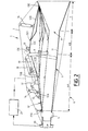
- Figure 2 is a longitudinal sectional view of the ramjet according to figure 1.
- Figures 3A-3D illustrate different configurations of the ramjet of Figures 1 and 2, corresponding to different speed ranges.
- the ramjet 1, shown in the figures, for an aircraft with supersonic and / or hypersonic flight, is intended to operate in a wide speed range, i.e. from a Mach number from 1-2 to a Mach number of 15-20.
- the combustion chamber 6 itself subdivides into a dissemination area 6A, where the supersonic combustion, and a zone of chamber 6B, where produces subsonic combustion behind the flame catchers 9, and where the supersonic combustion ends, the injectors 4 distributing the fuel throughout the vein.
- An ignition device 10 ( Figure 2) is provided at bedroom level 6B. Note that, as a fuel, we can consider using kerosene for the Mach of weakest flights (up to Mach 8) (possibly with a hydrogen bubbler so as to facilitate the ignition of the ramjet) and then hydrogen for higher Machs. Other fuels, such as methane, endothermic hydrocarbons, synthetic fuels, can also be used for an engine of this type.
- the body 5 of the ramjet as a whole has a form of rectangular cross section pipe, consisting generally of four walls two to two opposite, of which only the lower 11 and upper 12 walls are visible in the figures. For reasons of clarity, the corresponding side walls have not been shown on the drawing.
- the upper wall 12 consists of plates 12A-12D hinged together and at the ends of the wall 12 by respective axes 13A-13E transverse to the longitudinal extension of the body 5 of the ramjet.
- the plate 12D on the side of the nozzle 7, having a cross section triangular cross section of convergent / divergent profile, of which a vertex 12D.1 is oriented towards the interior of the body 5 of the ramjet and the other two vertices correspond to the axes of articulation 13D and 13E, structure linked to the location and to the function of said plate 12D, constituting in fact a wall of the nozzle 7.
- the implementation of the ramjet supposes that, having received a signal from a device 20 which measures the thrust, which is an integral linear function of operating efficiency of the ramjet, the on-board computer 21 of the aircraft tends constantly reaching an optimal geometry of the part passage of the combustion chamber (body 5 of the ramjet) thanks to the corresponding actuation of the cylinders control 14, 15, 16 of the hinged plates 12A-12D of the wall 12.
- a thrust sensor detecting the value of the longitudinal (axial) force generated during the operation of the ramjet, that is to say the thrust.
- the thrust value is determined by the efficiency of the operating process: combustion efficiency and total pressure recovery report (function of total hydraulic losses of the ramjet).
- the level of these two parameters depend on the geometry of the part of passage (at each point of the trajectory) and efficiency stabilization means (flame holder 9), which actually also represent a geometric command.
- the regulation acts on the system order to have the maximum performance from basically a few pressure measurements wisely provided in the engine and various other information (fuel flows, aircraft speed, by example).
- the push sensor is mostly useful during the ground development tests and possibly in flight, in order to verify that the envisaged regulation allows good to maximize propulsive performance.
- the combustion chamber operates on a subsonic combustion regime, corresponding to the extension flame catchers 9, placed in the diffuser of the room, in the passage part, by modifying the geometry of the passing part according to the orders sent by the on-board computer 21, receiving and processing the thrust sensor signals 20.
- the combustion chamber has a maximum passage cross section in a subsonic combustion regime for a Mach number 1-2 ( Figure 3A), which decreases towards Mach numbers plus high ( ⁇ 6), Figure 3B, by "bringing the plates together" articulated 12A-12D of the wall 12 of the opposite wall 11, while maintaining a neck geometry (convergent-divergent) in the transition zone between the combustion and the nozzle.
- the flame catchers 9 slow down the supersonic flow and a normal shock or an equivalent shock network is established between them and the injectors 4 (i.e. in the diffuser) and, after this shock, the flow becomes subsonic.
- the fuel flowing from the injectors is delivered to the flow, the ignition device 10 is activated and ignites the air-fuel mixture.
- the gas swirls and stable flames, i.e. stabilization zones appear. These flame zones stable promote the combustion process in the bedroom.
- Positioning of the injectors, as shown, upstream of the combustion chamber allows regular distribution the fuel in the air flow and get the disintegration of fuel streams, while ensuring safe pressurization of the combustion chamber, in the area where the geometric command of the passing part. Their positioning in the area of order would seriously complicate and even make it impossible under certain conditions the pressurization of the combustion chamber.
Landscapes
- Engineering & Computer Science (AREA)
- Chemical & Material Sciences (AREA)
- Combustion & Propulsion (AREA)
- Mechanical Engineering (AREA)
- General Engineering & Computer Science (AREA)
- Fuel-Injection Apparatus (AREA)
- Pressure-Spray And Ultrasonic-Wave- Spray Burners (AREA)
- Combustion Methods Of Internal-Combustion Engines (AREA)
- Electrical Control Of Air Or Fuel Supplied To Internal-Combustion Engine (AREA)
- Cylinder Crankcases Of Internal Combustion Engines (AREA)
- Physical Or Chemical Processes And Apparatus (AREA)
Claims (10)
- Staustrahltriebwerk für Über- und/oder Hyperschallflugzeug, das in einem großen Geschwindigkeitsbereich eingesetzt werden soll undeinen Sauerstoffträgereinlauf (3);mindestens eine Brennstoffeinspritzdüse (4);eine Brennkammer (6) mit veränderlicher Geometrie, in der das Sauerstoffträger-Brennstoffgemisch hergestellt wird, das verbrannt werden soll; undeine Auspuffdüse (7) zur Ableitung der aus der Brennkammer austretenden Gase, umfasst, dadurch gekennzeichnet, dass die genannte Brennkammer (6) und die genannte Auspuffdüse (7) von zwei Teilen eines Staustrahltriebwerkkörpers (5) gebildet werden und dass der genannte Staustrahltriebwerkkörper (5) in der Nähe des Übergangsbereichs (8) zwischen der Brennkammer (6) und der Auspuffdüse (7) eine veränderliche Geometrie besitzt, die allmählich von einem konvergierenden, dann divergierenden, Geschwindigkeiten von einer Machzahl unter 6 entsprechenden Längsabschnitt in einen deutlich konstanten, dann divergierenden, Geschwindigkeiten von einer Machzahl über 7 entsprechenden Abschnitt übergeht.
- Staustrahltriebwerk nach Anspruch 1, in dem der genannte Staustrahltriebwerkkörper (5) die allgemeine Form einer Leitung mit rechteckigem Querschnitt besitzt, die aus jeweils zwei einander gegenüberliegenden Wänden besteht,
dadurch gekennzeichnet, dass mindestens eine (12) der genannten Wände Platten (12A-12D) umfasst, die untereinander und an den Enden der genannten Wand (12) durch entsprechende quer zur Längsverlängerung des Körpers des Staustrahltriebwerks (5) liegende Achsbolzen (13A-13E)schwenkbar sind, wobei die relative Lage von mindestens einigen dieser Platten die veränderliche Geometrie des Übergangsbereichs (8) zwischen der Brennkammer (6) und der Auspuffdüse (7) bestimmt. - Staustrahltriebwerk nach Anspruch 2,
dadurch gekennzeichnet, dass, um die relative Schwenkbewegung der genannten Platten zu ermöglichen, mindestens bestimmte von ihnen (12A, 12C) aus zwei Teilen gefertigt sind, die einen Überlappungsbereich (12A.1, 12C.1) aufweisen. - Staustrahltriebwerk nach Anspruch 2 oder Anspruch 3,
dadurch gekennzeichnet, dass die Platte (12D) auf der Seite der Auspuffdüse (7) einen dreieckigen Querschnitt hat, von dem eine Spitze (12D.1) auf den Innenraum des Staustrahltriebwerkkörpers (5) gerichtet ist, wobei die beiden anderen Spitzen den jeweiligen Schwenkachsen (13D, 13E) der genannten Platte (12D) entsprechen. - Staustrahltriebwerk nach einem beliebigen der Ansprüche 2 bis 4,
dadurch gekennzeichnet, dass die Betätigung der genannten Gelenkplatten (12A-12D) und/oder der Flammenhalter (9) durch eine Gruppe von Kolben-Zylinder-Einheiten (14, 15, 16, 18) oder analogen Bauteilen erfolgt, die vom Bordcomputer (21) des Flugzeugs in Abhängigkeit von Signalen gesteuert werden, die von einer Vorrichtung (20) zur Messung einer mit der Fluggeschwindigkeit verbundenen Parameters stammen. - Staustrahltriebwerk nach Anspruch 5,
dadurch gekennzeichnet, dass das genannte Messgerät mindestens einen Schubkraftmessfühler (20) und/oder in der Brennkammer angeordnete Mittel zur Messung des statischen Drucks umfasst. - Staustrahltriebwerk nach einem beliebigen der Ansprüche 1 bis 6,
dadurch gekennzeichnet, dass die Brennkammer (6) unterteilt ist in einen Diffusionsbereich (6A), in dem die Überschallverbrennung beginnt, und einen Kammerbereich (6B), in dem die Unterschallverbrennung erfolgt, der hinter den einziehbaren Flammenhaltern (9) liegt und in dem die Überschallverbrennung endet. - Staustrahltriebwerk nach einem beliebigen der Ansprüche 1 bis 7,
dadurch gekennzeichnet, dass die Brennstoffeinspritzdüsen (4) direkt vor der Brennkammer (6) in deren Achse und in Höhe des Sauerstoffträgereinlaufs (3) angeordnet sind, wodurch die Verteilung im gesamten Strom gewährleistet wird. - Staustrahltriebwerk nach einem beliebigen der Ansprüche 1 bis 8,
dadurch gekennzeichnet, dass eine Zündvorrichtung (10) in der Brennkammer vorgesehen ist. - Staustrahltriebwerk nach einem beliebigen der Ansprüche 1 bis 9,
dadurch gekennzeichnet, dass für die Machzahlen unter 8 als Brennstoff Kerosin und Wasserstoff für die Machzahlen über 8 verwendet wird.
Applications Claiming Priority (2)
| Application Number | Priority Date | Filing Date | Title |
|---|---|---|---|
| FR9508417 | 1995-07-12 | ||
| FR9508417A FR2736684B1 (fr) | 1995-07-12 | 1995-07-12 | Statoreacteur pour aeronef a vol supersonique et/ou hypersonique |
Publications (2)
| Publication Number | Publication Date |
|---|---|
| EP0753653A1 EP0753653A1 (de) | 1997-01-15 |
| EP0753653B1 true EP0753653B1 (de) | 1999-12-01 |
Family
ID=9480916
Family Applications (1)
| Application Number | Title | Priority Date | Filing Date |
|---|---|---|---|
| EP96401422A Expired - Lifetime EP0753653B1 (de) | 1995-07-12 | 1996-06-27 | Staustrahltriebwerk für Über- und/oder Hyperschallflugzeug |
Country Status (8)
| Country | Link |
|---|---|
| US (1) | US5727382A (de) |
| EP (1) | EP0753653B1 (de) |
| JP (1) | JP3926870B2 (de) |
| CA (1) | CA2180502C (de) |
| DE (1) | DE69605364T2 (de) |
| ES (1) | ES2140801T3 (de) |
| FR (1) | FR2736684B1 (de) |
| RU (1) | RU2121592C1 (de) |
Families Citing this family (21)
| Publication number | Priority date | Publication date | Assignee | Title |
|---|---|---|---|---|
| FR2750169B1 (fr) * | 1996-06-24 | 1998-08-21 | Aerospatiale | Dispositif d'injection de combustible pour statoreacteur fonctionnant a un nombre de mach eleve |
| FR2750170B1 (fr) * | 1996-06-24 | 1998-08-21 | Aerospatiale | Mat d'injection de combustible pour statoreacteur fonctionnant a un nombre de mach eleve |
| FR2765272B1 (fr) * | 1997-06-26 | 1999-08-20 | Snecma | Arriere-corps ejecteur et melangeur de turbomachine |
| FR2813344B1 (fr) * | 2000-08-28 | 2002-11-29 | Aerospatiale Matra Missiles | Systeme d'obturation pour un orifice d'un conduit, en particulier pour un orifice d'une voie d'introduction d'air dans la chambre de combustion d'un statoreacteur |
| RU2182672C1 (ru) * | 2001-01-15 | 2002-05-20 | Акционерное общество открытого типа Авиамоторный научно-технический комплекс "Союз" | Выходное двухмерное сопло для воздушно-реактивного двигателя |
| FR2829188B1 (fr) | 2001-09-04 | 2006-02-10 | Aerospatiale Matra Missiles | Statoreacteur pour aeronef a vol supersonique et hypersonique |
| AUPR853401A0 (en) * | 2001-10-29 | 2001-11-29 | Arnold, Phillip John | Harmonic synchroniser system |
| US6715293B2 (en) * | 2002-03-28 | 2004-04-06 | United Technologies Corporation | Scram jet engine design |
| US6883330B2 (en) * | 2002-10-02 | 2005-04-26 | United Technologies Corporation | Variable geometry inlet design for scram jet engine |
| US7188477B2 (en) * | 2004-04-21 | 2007-03-13 | United Technologies Corporation | High temperature dynamic seal for scramjet variable geometry |
| DE102006056355A1 (de) * | 2006-11-29 | 2008-06-05 | Airbus Deutschland Gmbh | Antriebsvorrichtung zum Betrieb mit mehreren Kraftstoffen für ein Flugzeug |
| FR2921977B1 (fr) * | 2007-10-08 | 2012-09-21 | Airbus France | Turbomoteur a double flux pour aeronef |
| US8484980B1 (en) * | 2009-11-19 | 2013-07-16 | The United States Of America As Represented By The Administrator Of National Aeronautics And Space Administration | Dual-mode combustor |
| CN105715408A (zh) * | 2014-12-03 | 2016-06-29 | 中国航空工业集团公司沈阳发动机设计研究所 | 一种新型的二元矢量喷管 |
| US10190539B2 (en) * | 2015-07-01 | 2019-01-29 | The Boeing Company | Inlet flow restrictor |
| US11697780B1 (en) | 2018-01-18 | 2023-07-11 | Reaction Systems, Inc. | Decahydronaphthalene as an endothermic fuel for hypersonic vehicles |
| US11111448B1 (en) | 2018-01-18 | 2021-09-07 | Reaction Systems Inc. | Decahydronaphthalene as an endothermic fuel for hypersonic vehicles |
| US12084343B1 (en) | 2018-08-14 | 2024-09-10 | Reaction Systems, Inc. | Transient N2O decomposition process and reactor |
| US11421628B2 (en) * | 2018-09-12 | 2022-08-23 | University Of Florida Research Foundation, Incorporated | Fuel injector for hypersonic jet engine operation |
| CN114412655B (zh) * | 2021-12-21 | 2023-11-14 | 西北工业大学 | 宽域高超声速冲压发动机燃烧室尾喷管一体化可调结构 |
| CN119914898B (zh) * | 2025-01-02 | 2025-11-11 | 中国航空发动机研究院 | 宽速域超燃冲压燃烧室及超燃冲压发动机及组合动力装置 |
Family Cites Families (6)
| Publication number | Priority date | Publication date | Assignee | Title |
|---|---|---|---|---|
| US3279194A (en) * | 1962-08-14 | 1966-10-18 | Garrett Corp | Aerothermodynamic duct and control means therefor |
| US4821512A (en) * | 1987-05-05 | 1989-04-18 | United Technologies Corporation | Piloting igniter for supersonic combustor |
| GB2222635B (en) * | 1987-10-24 | 1992-05-27 | British Aerospace | Propulsion units for aerospace vehicles |
| US5081831A (en) * | 1989-03-23 | 1992-01-21 | General Electric Company | Scramjet combustor |
| US5072581A (en) * | 1989-03-23 | 1991-12-17 | General Electric Company | Scramjet combustor |
| US5226455A (en) * | 1990-12-17 | 1993-07-13 | Dupont Anthony A | Variable geometry duct seal |
-
1995
- 1995-07-12 FR FR9508417A patent/FR2736684B1/fr not_active Expired - Lifetime
-
1996
- 1996-06-27 US US08/671,345 patent/US5727382A/en not_active Expired - Lifetime
- 1996-06-27 ES ES96401422T patent/ES2140801T3/es not_active Expired - Lifetime
- 1996-06-27 DE DE69605364T patent/DE69605364T2/de not_active Expired - Lifetime
- 1996-06-27 EP EP96401422A patent/EP0753653B1/de not_active Expired - Lifetime
- 1996-07-04 CA CA002180502A patent/CA2180502C/fr not_active Expired - Fee Related
- 1996-07-10 JP JP18094396A patent/JP3926870B2/ja not_active Expired - Lifetime
- 1996-07-11 RU RU96115350A patent/RU2121592C1/ru active
Also Published As
| Publication number | Publication date |
|---|---|
| US5727382A (en) | 1998-03-17 |
| CA2180502A1 (fr) | 1997-01-13 |
| CA2180502C (fr) | 2006-09-12 |
| DE69605364D1 (de) | 2000-01-05 |
| RU2121592C1 (ru) | 1998-11-10 |
| DE69605364T2 (de) | 2000-04-13 |
| FR2736684B1 (fr) | 1997-09-12 |
| EP0753653A1 (de) | 1997-01-15 |
| JPH0932640A (ja) | 1997-02-04 |
| FR2736684A1 (fr) | 1997-01-17 |
| ES2140801T3 (es) | 2000-03-01 |
| JP3926870B2 (ja) | 2007-06-06 |
Similar Documents
| Publication | Publication Date | Title |
|---|---|---|
| EP0753653B1 (de) | Staustrahltriebwerk für Über- und/oder Hyperschallflugzeug | |
| CA2198420C (fr) | Dispositif d'injection de combustible pour statoreacteur d'aeronef | |
| EP0846920B1 (de) | Transpirationsgekühlte Brennstoffeinspritzstrebe | |
| FR2644875A1 (fr) | Dispositif de combustion pour statoreacteur a combustion supersonique et procede pour faire fonctionner un tel dispositif | |
| EP1808593A1 (de) | Strömungsmischer mit veränderlichem Querschnitt für Zweistrom-Turbinentriebwerke von Überschallflugzeugen | |
| CA2743009C (fr) | Entree d'air d'un moteur d'avion a helices propulsives non carenees | |
| EP1950405B1 (de) | Strömungsmischer mit veränderlichem Querschnitt für Zweistrom-Turbinentriebwerke von Überschallflugzeugen | |
| EP1020631B1 (de) | Strahltriebdüse mit integrierter Schubumkehrvorrichtung | |
| EP3325792B1 (de) | Flugzeugantriebsbaugruppe mit einem schubumkehrer | |
| CA2180501C (fr) | Statoreacteur pour aeronef a vol supersonique et/ou hypersonique | |
| EP3530908A1 (de) | Brennkammer, die zwei typen von injektoren umfasst, in denen die dichtungsorgane eine unterschiedliche öffnungsschwelle besitzen | |
| EP0793011B1 (de) | Staustrahltriebwerk mit variabler Geometrie | |
| EP1288480B1 (de) | Staustrahltriebwerk für Über- und Hyperschallflugzeug | |
| FR2653177A1 (fr) | Turbo-statoreacteur equipant des avions pour vol sub et/ou hypersonique. | |
| EP0526408A1 (de) | Glühkerze für Diesel-Brennkraftmaschinen | |
| EP4004443B1 (de) | Brennkammer mit sekundäreinspritzsystemen und verfahren zur kraftstoffversorgung | |
| EP4042070B1 (de) | Vorverdampfungsrohr für die brennkammer eines turbinenmotors | |
| BE520316A (fr) | Perfectionnements apportes aux tuyeres deflectrices du jet propulseur des avions a reaction | |
| WO2025168900A1 (fr) | Système d'injection d'hydrogène et d'air | |
| FR3162499A1 (fr) | Dispositif d’injection avec injecteur avec combustion riche-pauvre pour chambre de combustion |
Legal Events
| Date | Code | Title | Description |
|---|---|---|---|
| PUAI | Public reference made under article 153(3) epc to a published international application that has entered the european phase |
Free format text: ORIGINAL CODE: 0009012 |
|
| AK | Designated contracting states |
Kind code of ref document: A1 Designated state(s): BE DE ES GB IT NL SE |
|
| 17P | Request for examination filed |
Effective date: 19970130 |
|
| 17Q | First examination report despatched |
Effective date: 19980803 |
|
| GRAG | Despatch of communication of intention to grant |
Free format text: ORIGINAL CODE: EPIDOS AGRA |
|
| GRAG | Despatch of communication of intention to grant |
Free format text: ORIGINAL CODE: EPIDOS AGRA |
|
| GRAH | Despatch of communication of intention to grant a patent |
Free format text: ORIGINAL CODE: EPIDOS IGRA |
|
| GRAH | Despatch of communication of intention to grant a patent |
Free format text: ORIGINAL CODE: EPIDOS IGRA |
|
| GRAA | (expected) grant |
Free format text: ORIGINAL CODE: 0009210 |
|
| AK | Designated contracting states |
Kind code of ref document: B1 Designated state(s): BE DE ES GB IT NL SE |
|
| RAP2 | Party data changed (patent owner data changed or rights of a patent transferred) |
Owner name: AEROSPATIALE MATRA |
|
| REF | Corresponds to: |
Ref document number: 69605364 Country of ref document: DE Date of ref document: 20000105 |
|
| ITF | It: translation for a ep patent filed | ||
| NLT2 | Nl: modifications (of names), taken from the european patent patent bulletin |
Owner name: AEROSPATIALE MATRA |
|
| REG | Reference to a national code |
Ref country code: ES Ref legal event code: FG2A Ref document number: 2140801 Country of ref document: ES Kind code of ref document: T3 |
|
| GBT | Gb: translation of ep patent filed (gb section 77(6)(a)/1977) |
Effective date: 20000221 |
|
| PLBE | No opposition filed within time limit |
Free format text: ORIGINAL CODE: 0009261 |
|
| STAA | Information on the status of an ep patent application or granted ep patent |
Free format text: STATUS: NO OPPOSITION FILED WITHIN TIME LIMIT |
|
| 26N | No opposition filed | ||
| REG | Reference to a national code |
Ref country code: GB Ref legal event code: IF02 |
|
| PGFP | Annual fee paid to national office [announced via postgrant information from national office to epo] |
Ref country code: ES Payment date: 20150629 Year of fee payment: 20 Ref country code: GB Payment date: 20150619 Year of fee payment: 20 Ref country code: DE Payment date: 20150612 Year of fee payment: 20 Ref country code: SE Payment date: 20150617 Year of fee payment: 20 |
|
| PGFP | Annual fee paid to national office [announced via postgrant information from national office to epo] |
Ref country code: NL Payment date: 20150521 Year of fee payment: 20 Ref country code: IT Payment date: 20150612 Year of fee payment: 20 |
|
| PGFP | Annual fee paid to national office [announced via postgrant information from national office to epo] |
Ref country code: BE Payment date: 20150630 Year of fee payment: 20 |
|
| REG | Reference to a national code |
Ref country code: DE Ref legal event code: R071 Ref document number: 69605364 Country of ref document: DE |
|
| REG | Reference to a national code |
Ref country code: NL Ref legal event code: MK Effective date: 20160626 |
|
| REG | Reference to a national code |
Ref country code: GB Ref legal event code: PE20 Expiry date: 20160626 |
|
| PG25 | Lapsed in a contracting state [announced via postgrant information from national office to epo] |
Ref country code: GB Free format text: LAPSE BECAUSE OF EXPIRATION OF PROTECTION Effective date: 20160626 |
|
| REG | Reference to a national code |
Ref country code: SE Ref legal event code: EUG |
|
| REG | Reference to a national code |
Ref country code: ES Ref legal event code: FD2A Effective date: 20161004 |
|
| PG25 | Lapsed in a contracting state [announced via postgrant information from national office to epo] |
Ref country code: ES Free format text: LAPSE BECAUSE OF EXPIRATION OF PROTECTION Effective date: 20160628 |