EP0753653B1 - Ramjet for supersonic and/or hypersonic vehicle - Google Patents
Ramjet for supersonic and/or hypersonic vehicle Download PDFInfo
- Publication number
- EP0753653B1 EP0753653B1 EP96401422A EP96401422A EP0753653B1 EP 0753653 B1 EP0753653 B1 EP 0753653B1 EP 96401422 A EP96401422 A EP 96401422A EP 96401422 A EP96401422 A EP 96401422A EP 0753653 B1 EP0753653 B1 EP 0753653B1
- Authority
- EP
- European Patent Office
- Prior art keywords
- jet engine
- combustion chamber
- ram jet
- engine according
- combustion
- Prior art date
- Legal status (The legal status is an assumption and is not a legal conclusion. Google has not performed a legal analysis and makes no representation as to the accuracy of the status listed.)
- Expired - Lifetime
Links
- 238000002485 combustion reaction Methods 0.000 claims description 54
- 239000000446 fuel Substances 0.000 claims description 21
- 230000007704 transition Effects 0.000 claims description 10
- 239000007800 oxidant agent Substances 0.000 claims description 7
- 239000000203 mixture Substances 0.000 claims description 5
- 238000011144 upstream manufacturing Methods 0.000 claims description 5
- UFHFLCQGNIYNRP-UHFFFAOYSA-N Hydrogen Chemical compound [H][H] UFHFLCQGNIYNRP-UHFFFAOYSA-N 0.000 claims description 4
- 239000001257 hydrogen Substances 0.000 claims description 4
- 229910052739 hydrogen Inorganic materials 0.000 claims description 4
- 230000001590 oxidative effect Effects 0.000 claims description 4
- 239000007789 gas Substances 0.000 claims description 3
- 239000003350 kerosene Substances 0.000 claims description 3
- 230000033001 locomotion Effects 0.000 claims description 3
- 238000009792 diffusion process Methods 0.000 claims description 2
- 230000003068 static effect Effects 0.000 claims description 2
- 230000035939 shock Effects 0.000 description 6
- 208000031968 Cadaver Diseases 0.000 description 4
- 230000033228 biological regulation Effects 0.000 description 2
- 230000007423 decrease Effects 0.000 description 2
- 235000021183 entrée Nutrition 0.000 description 2
- VNWKTOKETHGBQD-UHFFFAOYSA-N methane Chemical compound C VNWKTOKETHGBQD-UHFFFAOYSA-N 0.000 description 2
- 230000006641 stabilisation Effects 0.000 description 2
- 238000011105 stabilization Methods 0.000 description 2
- 210000003462 vein Anatomy 0.000 description 2
- 101100114365 Caenorhabditis elegans col-8 gene Proteins 0.000 description 1
- RRLHMJHRFMHVNM-BQVXCWBNSA-N [(2s,3r,6r)-6-[5-[5-hydroxy-3-(4-hydroxyphenyl)-4-oxochromen-7-yl]oxypentoxy]-2-methyl-3,6-dihydro-2h-pyran-3-yl] acetate Chemical compound C1=C[C@@H](OC(C)=O)[C@H](C)O[C@H]1OCCCCCOC1=CC(O)=C2C(=O)C(C=3C=CC(O)=CC=3)=COC2=C1 RRLHMJHRFMHVNM-BQVXCWBNSA-N 0.000 description 1
- 230000006978 adaptation Effects 0.000 description 1
- 230000000903 blocking effect Effects 0.000 description 1
- 238000009530 blood pressure measurement Methods 0.000 description 1
- 210000003679 cervix uteri Anatomy 0.000 description 1
- 238000005474 detonation Methods 0.000 description 1
- 238000011981 development test Methods 0.000 description 1
- 230000008034 disappearance Effects 0.000 description 1
- 230000010006 flight Effects 0.000 description 1
- 229930195733 hydrocarbon Natural products 0.000 description 1
- 150000002430 hydrocarbons Chemical class 0.000 description 1
- 238000012886 linear function Methods 0.000 description 1
- 238000000034 method Methods 0.000 description 1
- 238000012545 processing Methods 0.000 description 1
- 230000000750 progressive effect Effects 0.000 description 1
- 230000001141 propulsive effect Effects 0.000 description 1
- 238000011084 recovery Methods 0.000 description 1
- 239000003381 stabilizer Substances 0.000 description 1
Images


Classifications
-
- F—MECHANICAL ENGINEERING; LIGHTING; HEATING; WEAPONS; BLASTING
- F02—COMBUSTION ENGINES; HOT-GAS OR COMBUSTION-PRODUCT ENGINE PLANTS
- F02K—JET-PROPULSION PLANTS
- F02K7/00—Plants in which the working fluid is used in a jet only, i.e. the plants not having a turbine or other engine driving a compressor or a ducted fan; Control thereof
- F02K7/10—Plants in which the working fluid is used in a jet only, i.e. the plants not having a turbine or other engine driving a compressor or a ducted fan; Control thereof characterised by having ram-action compression, i.e. aero-thermo-dynamic-ducts or ram-jet engines
Definitions
- the present invention relates to a ramjet for aircraft supersonic and / or hypersonic flight, intended to operate over a wide speed range.
- the speed range considered is thus between Mach numbers of 1-2 to 15-20.
- the present invention aims to fill this gap.
- Such a structure ensures progressive adaptation, in function of flight speed, body geometry ramjet as a whole but especially in the vicinity of the transition between the combustion chamber and the exhaust nozzle (nozzle neck) to keep, in wide range of speeds indicated, flight conditions optimal, in particular a maximum thrust value regardless of external conditions (consumption of fuel, aerodynamic pressure, flow profile oxidizer (air) in the corresponding input). In others terms, this amounts in particular to "disappearing" the cervix of nozzle (converging-diverging geometry) existing at "low” speed for ultimately (Mach number equal or greater than about 8) get a constant section of the combustion chamber, followed by the divergent section of the exhaust nozzle.
- the ramjet body conforms to the invention has the general form of a rectangular cross section, consisting of walls two to two opposite, at least one of said walls comprises plates hinged together and at the ends of said wall by respective axes transverse to the extension length of the ramjet body, position relative of at least some of said plates defining the evolutionary geometry of the transition zone between the combustion chamber and exhaust nozzle.
- At least some of them are made in two parts with an overlapping area.
- the plate on the side of the exhaust nozzle, has a cross section triangular, one vertex of which is oriented towards the interior of the ramjet body, the other two vertices corresponding to the respective articulation axes of said plate.
- the actuation said articulated plates and / or flame catchers is produced by a set of actuators or the like, controlled by the on-board computer of the aircraft according to signals from a device for measuring a parameter linked to the flight speed.
- said measuring device comprises at least a thrust sensor and / or pressure measuring means static arranged in the combustion chamber.
- combustion chamber is subdivided into an area of diffusion, where supersonic combustion begins, and a chamber area, where subsonic combustion occurs, behind retractable flame catchers, and where ends supersonic combustion.
- the fuel injectors can be arranged immediately upstream of the combustion chamber, in the axis thereof and at the level of the oxidant inlet, ensuring a distribution of fuel throughout the vein, while an ignition device is advantageously provided in the combustion chamber.
- kerosene be used for the lowest flight Machs and hydrogen for the higher Machs.
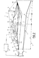
- Figure 1 is a schematic perspective view of a exemplary embodiment of a ramjet according to the invention.
- Figure 2 is a longitudinal sectional view of the ramjet according to figure 1.
- Figures 3A-3D illustrate different configurations of the ramjet of Figures 1 and 2, corresponding to different speed ranges.
- the ramjet 1, shown in the figures, for an aircraft with supersonic and / or hypersonic flight, is intended to operate in a wide speed range, i.e. from a Mach number from 1-2 to a Mach number of 15-20.
- the combustion chamber 6 itself subdivides into a dissemination area 6A, where the supersonic combustion, and a zone of chamber 6B, where produces subsonic combustion behind the flame catchers 9, and where the supersonic combustion ends, the injectors 4 distributing the fuel throughout the vein.
- An ignition device 10 ( Figure 2) is provided at bedroom level 6B. Note that, as a fuel, we can consider using kerosene for the Mach of weakest flights (up to Mach 8) (possibly with a hydrogen bubbler so as to facilitate the ignition of the ramjet) and then hydrogen for higher Machs. Other fuels, such as methane, endothermic hydrocarbons, synthetic fuels, can also be used for an engine of this type.
- the body 5 of the ramjet as a whole has a form of rectangular cross section pipe, consisting generally of four walls two to two opposite, of which only the lower 11 and upper 12 walls are visible in the figures. For reasons of clarity, the corresponding side walls have not been shown on the drawing.
- the upper wall 12 consists of plates 12A-12D hinged together and at the ends of the wall 12 by respective axes 13A-13E transverse to the longitudinal extension of the body 5 of the ramjet.
- the plate 12D on the side of the nozzle 7, having a cross section triangular cross section of convergent / divergent profile, of which a vertex 12D.1 is oriented towards the interior of the body 5 of the ramjet and the other two vertices correspond to the axes of articulation 13D and 13E, structure linked to the location and to the function of said plate 12D, constituting in fact a wall of the nozzle 7.
- the implementation of the ramjet supposes that, having received a signal from a device 20 which measures the thrust, which is an integral linear function of operating efficiency of the ramjet, the on-board computer 21 of the aircraft tends constantly reaching an optimal geometry of the part passage of the combustion chamber (body 5 of the ramjet) thanks to the corresponding actuation of the cylinders control 14, 15, 16 of the hinged plates 12A-12D of the wall 12.
- a thrust sensor detecting the value of the longitudinal (axial) force generated during the operation of the ramjet, that is to say the thrust.
- the thrust value is determined by the efficiency of the operating process: combustion efficiency and total pressure recovery report (function of total hydraulic losses of the ramjet).
- the level of these two parameters depend on the geometry of the part of passage (at each point of the trajectory) and efficiency stabilization means (flame holder 9), which actually also represent a geometric command.
- the regulation acts on the system order to have the maximum performance from basically a few pressure measurements wisely provided in the engine and various other information (fuel flows, aircraft speed, by example).
- the push sensor is mostly useful during the ground development tests and possibly in flight, in order to verify that the envisaged regulation allows good to maximize propulsive performance.
- the combustion chamber operates on a subsonic combustion regime, corresponding to the extension flame catchers 9, placed in the diffuser of the room, in the passage part, by modifying the geometry of the passing part according to the orders sent by the on-board computer 21, receiving and processing the thrust sensor signals 20.
- the combustion chamber has a maximum passage cross section in a subsonic combustion regime for a Mach number 1-2 ( Figure 3A), which decreases towards Mach numbers plus high ( ⁇ 6), Figure 3B, by "bringing the plates together" articulated 12A-12D of the wall 12 of the opposite wall 11, while maintaining a neck geometry (convergent-divergent) in the transition zone between the combustion and the nozzle.
- the flame catchers 9 slow down the supersonic flow and a normal shock or an equivalent shock network is established between them and the injectors 4 (i.e. in the diffuser) and, after this shock, the flow becomes subsonic.
- the fuel flowing from the injectors is delivered to the flow, the ignition device 10 is activated and ignites the air-fuel mixture.
- the gas swirls and stable flames, i.e. stabilization zones appear. These flame zones stable promote the combustion process in the bedroom.
- Positioning of the injectors, as shown, upstream of the combustion chamber allows regular distribution the fuel in the air flow and get the disintegration of fuel streams, while ensuring safe pressurization of the combustion chamber, in the area where the geometric command of the passing part. Their positioning in the area of order would seriously complicate and even make it impossible under certain conditions the pressurization of the combustion chamber.
Landscapes
- Engineering & Computer Science (AREA)
- Chemical & Material Sciences (AREA)
- Combustion & Propulsion (AREA)
- Mechanical Engineering (AREA)
- General Engineering & Computer Science (AREA)
- Fuel-Injection Apparatus (AREA)
- Pressure-Spray And Ultrasonic-Wave- Spray Burners (AREA)
- Combustion Methods Of Internal-Combustion Engines (AREA)
- Cylinder Crankcases Of Internal Combustion Engines (AREA)
- Electrical Control Of Air Or Fuel Supplied To Internal-Combustion Engine (AREA)
- Physical Or Chemical Processes And Apparatus (AREA)
Description
La présente invention concerne un statoréacteur pour aéronef à vol supersonique et/ou hypersonique, destiné à fonctionner sur une large plage de vitesses. La plage de vitesses envisagée se situe ainsi entre des nombres de Mach de 1-2 à 15-20.The present invention relates to a ramjet for aircraft supersonic and / or hypersonic flight, intended to operate over a wide speed range. The speed range considered is thus between Mach numbers of 1-2 to 15-20.
Jusqu'à présent, il n'existe pas de statoréacteur susceptible de fonctionner, en conservant constamment une efficacité maximale, dans une telle plage de vitesses.So far, there is no ramjet capable of to function, constantly maintaining efficiency maximum, in such a speed range.
La présente invention a pour but de combler cette lacune.The present invention aims to fill this gap.
A cet effet, le statoréacteur pour aéronef à vol supersonique et/ou hypersonique, destiné à fonctionner sur une large plage de vitesses, comprenant :
- une entrée de comburant
- au moins un injecteur de combustible ;
- une chambre de combustion à géométrie variable, dans laquelle est effectué le mélange comburant-combustible destiné à être brûlé ; et
- une tuyère d'échappement, destinée à canaliser les gaz sortant de la chambre de combustion,
- an oxidizer entry
- at least one fuel injector;
- a combustion chamber with variable geometry, in which the oxidant-fuel mixture intended to be burned is carried out; and
- an exhaust nozzle, intended to channel the gases leaving the combustion chamber,
Une telle structure assure une adaptation progressive, en fonction de la vitesse de vol, de la géométrie du corps de statoréacteur dans son ensemble mais notamment au voisinage de la transition entre la chambre de combustion et la tuyère d'échappement (col de tuyère) pour conserver, dans la large plage de vitesses indiquée, des conditions de vol optimales, en particulier une valeur de poussée maximale indépendamment des conditions externes (consommation de combustible, pression aérodynamique, profil du flux de comburant (air) dans l'entrée correspondante). En d'autres termes, cela revient notamment à faire "disparaítre" le col de tuyère (géométrie convergente-divergente) existant à "faible" vitesse pour en définitive (nombre de Mach égal ou supérieur à environ 8) obtenir une section constante de la chambre de combustion, suivie par la section divergente de la tuyère d'échappement.Such a structure ensures progressive adaptation, in function of flight speed, body geometry ramjet as a whole but especially in the vicinity of the transition between the combustion chamber and the exhaust nozzle (nozzle neck) to keep, in wide range of speeds indicated, flight conditions optimal, in particular a maximum thrust value regardless of external conditions (consumption of fuel, aerodynamic pressure, flow profile oxidizer (air) in the corresponding input). In others terms, this amounts in particular to "disappearing" the cervix of nozzle (converging-diverging geometry) existing at "low" speed for ultimately (Mach number equal or greater than about 8) get a constant section of the combustion chamber, followed by the divergent section of the exhaust nozzle.
On remarquera que le document US-A-3 279 194 décrit un conduit aérothermodynamique à tuyère convergente-divergente, la paroi de fond dudit conduit étant rigidement réglable en inclinaison pour obtenir la détonation continue du mélange combustible-air sur une large plage de nombres de Mach supersoniques et hypersoniques.Note that document US-A-3,279,194 describes a aerothermodynamic duct with convergent-divergent nozzle, the bottom wall of said duct being rigidly adjustable tilt to achieve continuous detonation fuel-air mixture over a wide range of numbers of supersonic and hypersonic Mach.
Dans le cas où le corps du statoréacteur conforme à l'invention présente la forme générale d'une conduite de section transversale rectangulaire, constituée de parois deux à deux opposées, au moins une desdites parois comporte des plaques articulées entre elles et aux extrémités de ladite paroi par des axes respectifs transversaux à l'extension longitudinale du corps du statoréacteur, la position relative d'au moins certaines desdites plaques définissant la géométrie évolutive de la zone de transition entre la chambre de combustion et la tuyère d'échappement. If the ramjet body conforms to the invention has the general form of a rectangular cross section, consisting of walls two to two opposite, at least one of said walls comprises plates hinged together and at the ends of said wall by respective axes transverse to the extension length of the ramjet body, position relative of at least some of said plates defining the evolutionary geometry of the transition zone between the combustion chamber and exhaust nozzle.
De préférence, pour permettre le mouvement relatif d'articulation desdites plaques, au moins certaines d'entre elles sont réalisées en deux parties présentant une zone de chevauchement.Preferably, to allow relative movement of the joint of said plates, at least some of them are made in two parts with an overlapping area.
Par ailleurs, il est avantageux que la plaque, du côté de la tuyère d'échappement, présente une section transversale triangulaire, dont un sommet est orienté vers l'intérieur du corps du statoréacteur, les deux autres sommets correspondant aux axes d'articulation respectifs de ladite plaque.Furthermore, it is advantageous that the plate, on the side of the exhaust nozzle, has a cross section triangular, one vertex of which is oriented towards the interior of the ramjet body, the other two vertices corresponding to the respective articulation axes of said plate.
Selon une autre caractéristique de l'invention, l'actionnement desdites plaques articulées et/ou des accroche-flammes est réalisé par un ensemble de vérins ou analogues, pilotés par l'ordinateur de bord de l'aéronef en fonction de signaux issus d'un dispositif de mesure d'un paramètre lié à la vitesse de vol.According to another characteristic of the invention, the actuation said articulated plates and / or flame catchers is produced by a set of actuators or the like, controlled by the on-board computer of the aircraft according to signals from a device for measuring a parameter linked to the flight speed.
De préférence, ledit dispositif de mesure comprend au moins un capteur de poussée et/ou des moyens de mesure de pression statique disposés dans la chambre de combustion.Preferably, said measuring device comprises at least a thrust sensor and / or pressure measuring means static arranged in the combustion chamber.
De plus, la chambre de combustion est subdivisée en une zone de diffusion, où commence la combustion supersonique, et une zone de chambre, où se produit la combustion subsonique, derrière des accroche-flammes escamotables, et où se termine la combustion supersonique.In addition, the combustion chamber is subdivided into an area of diffusion, where supersonic combustion begins, and a chamber area, where subsonic combustion occurs, behind retractable flame catchers, and where ends supersonic combustion.
En outre, les injecteurs de combustible peuvent être disposés immédiatement en amont de la chambre de combustion, dans l'axe de celle-ci et au niveau de l'entrée de comburant, assurant une répartition du combustible dans toute la veine, tandis qu'un dispositif d'allumage est avantageusement prévu dans la chambre de combustion.In addition, the fuel injectors can be arranged immediately upstream of the combustion chamber, in the axis thereof and at the level of the oxidant inlet, ensuring a distribution of fuel throughout the vein, while an ignition device is advantageously provided in the combustion chamber.
Par ailleurs, il est préféré que, comme combustible, du kérosène soit utilisé pour les Mach de vol les plus faibles et de l'hydrogène pour les Mach plus élevés.Furthermore, it is preferred that, as a fuel, kerosene be used for the lowest flight Machs and hydrogen for the higher Machs.
Les figures du dessin annexé feront bien comprendre comment l'invention peut être réalisée. The figures in the accompanying drawing will make it clear how the invention can be realized.
La figure 1 est une vue schématique en perspective d'un exemple de réalisation d'un statoréacteur conforme à l'invention.Figure 1 is a schematic perspective view of a exemplary embodiment of a ramjet according to the invention.
La figure 2 est une vue en coupe longitudinale du statoréacteur selon la figure 1.Figure 2 is a longitudinal sectional view of the ramjet according to figure 1.
Les figures 3A-3D illustrent différentes configurations du statoréacteur des figures 1 et 2, correspondant à différents domaines de vitesses.Figures 3A-3D illustrate different configurations of the ramjet of Figures 1 and 2, corresponding to different speed ranges.
Le statoréacteur 1, montré sur les figures, pour aéronef à vol supersonique et/ou hypersonique, est destiné à fonctionner dans une large plage de vitesses, c'est-à-dire d'un nombre de Mach de 1-2 à un nombre de Mach de 15-20.The ramjet 1, shown in the figures, for an aircraft with supersonic and / or hypersonic flight, is intended to operate in a wide speed range, i.e. from a Mach number from 1-2 to a Mach number of 15-20.
Dans un carter ou enveloppe 2, le statoréacteur 1 comprend :
- une entrée de
comburant 3, notamment une prise d'air, en amont du moteur, implantée sous l'intrados du fuselage de l'aéronef associé au statoréacteur, - des injecteurs de
combustible 4, prévus en amont ducorps 5 du statoréacteur, - ledit
corps 5 se décomposant, comme on le voit mieux sur la figure 2, en une portion de chambre decombustion 6 et une portion detuyère 7, définissant entre elles, comme on le verra plus en détail par la suite, une zone de transition (ou col) 8, définie par une géométrie convergente-divergente évoluant, selon l'invention, en fonction de la vitesse, c'est-à-dire du nombre de Mach, de fonctionnement du statoréacteur.
- an
oxidizer inlet 3, in particular an air intake, upstream of the engine, located under the lower surface of the fuselage of the aircraft associated with the ramjet, -
fuel injectors 4, provided upstream of thebody 5 of the ramjet, - said
body 5 decomposing, as best seen in FIG. 2, into a portion ofcombustion chamber 6 and a portion ofnozzle 7, defining between them, as will be seen in more detail below, a transition zone (or neck) 8, defined by a converging-diverging geometry evolving, according to the invention, as a function of the speed, that is to say of the Mach number, of operation of the ramjet.
Par ailleurs, la chambre de combustion 6 elle-même se
subdivise en une zone de diffusion 6A, où commence la
combustion supersonique, et une zone de chambre 6B, où se
produit la combustion subsonique, derrière les accroche-flammes
9, et où se termine la combustion supersonique, les
injecteurs 4 répartissant le combustible dans toute la
veine. Un dispositif d'allumage 10 (figure 2) est prévu au
niveau de la chambre 6B. On notera que, comme combustible,
on peut envisager d'utiliser du kérosène pour les Mach de
vol les plus faibles (jusqu'à Mach 8) (éventuellement avec
un barbotate d'hydrogène de façon à faciliter l'allumage du
statoréacteur et l'éclatement du jet), puis de l'hydrogène
pour les Mach plus élevés. D'autres combustibles, tels que
du méthane, des hydrocarbures endothermiques, des
combustibles de synthèse, peuvent également être employés
pour un moteur de ce type.Furthermore, the
Dans l'exemple de réalisation représenté, le corps 5 du
statoréacteur présente, dans son ensemble, une forme de
conduite de section transversale rectangulaire, constituée
généralement de quatre parois deux à deux opposées, dont
seules les parois inférieure 11 et supérieure 12 sont
visibles sur les figures. Pour des raisons de clarté, les
parois latérales correspondantes n'ont pas été représentées
sur le dessin. Pour obtenir la géométrie évolutive objet de
l'invention, la paroi supérieure 12 est constituée de
plaques 12A-12D articulées entre elles et aux extrémités de
la paroi 12 par des axes respectifs 13A-13E transversaux à
l'extension longitudinale du corps 5 du statoréacteur. Pour
permettre le mouvement relatif d'articulation entre les
différentes plaques 12A-12D, certaines d'entre elles, comme
montré sur la figure 1, à savoir dans cet exemple les
plaques 12A et 12C, sont réalisées en deux parties présentant
une zone de chevauchement 12A.1, 12C.1 (non représenté
sur la figure 2).In the embodiment shown, the
Il est bien entendu qu'une telle configuration n'est nullement limitative, aussi bien en ce qui concerne la paroi mobile "choisie" que le nombre de plaques qui la constituent. En particulier, une autre paroi, ou plusieurs parois, du statoréacteur auraient pu être conçues pour présenter une telle "mobilité" dans le but d'atteindre l'objectif visé.It is understood that such a configuration is in no way limiting, both with regard to the wall mobile "chosen" as the number of plates that constitute it. In particular, another wall, or several walls, of the ramjet could have been designed to present a such "mobility" in order to achieve the objective.
On notera par ailleurs la structure particulière de la
plaque 12D, du côté de la tuyère 7, présentant une section
transversale triangulaire de profil convergent/divergent,
dont un sommet 12D.1 est orienté vers l'intérieur du corps 5
du statoréacteur et les deux autres sommets correspondent
aux axes d'articulation 13D et 13E, structure liée à l'emplacement
et à la fonction de ladite plaque 12D, constituant
en fait une paroi de la tuyère 7.Note also the particular structure of the
La mobilité des plaques 12A-12D est assurée, comme on le
voit sur la figure 2, par un ensemble de vérins 14, 15, 16,
éventuellement associés à une tringlerie correspondante (17
pour le vérin 15). De façon analogue, un vérin 18 assure le
positionnement et, éventuellement, l'escamotage (cavité 19)
de chaque accroche-flammes 9. L'ensemble des vérins et
tringleries ci-dessus a été omis sur la figure 1 pour des
raisons de clarté du dessin.The mobility of the
La mise en oeuvre du statoréacteur suppose que, ayant reçu
un signal d'un dispositif 20 qui mesure la poussée, qui est
une fonction linéaire intégrale de l'efficacité opératoire
du statoréacteur, l'ordinateur de bord 21 de l'aéronef tend
constamment à atteindre une géométrie optimale de la partie
de passage de la chambre de combustion (corps 5 du statoréacteur)
grâce à l'actionnement correspondant des vérins de
commande 14, 15, 16 des plaques articulées 12A-12D de la
paroi 12. Comme dispositif de mesure, on peut envisager
l'utilisation d'un capteur de poussée, détectant la valeur
de la force longitudinale (axiale) engendrée pendant le
fonctionnement du statoréacteur, c'est-à-dire la poussée. La
valeur de la poussée est déterminée par l'efficacité du
processus opératoire : l'efficacité de la combustion et le
rapport de récupération de pression totale (fonction des
pertes hydrauliques totales du statoréacteur). Le niveau de
ces deux paramètres dépend de la géométrie de la partie de
passage (à chaque point de la trajectoire) et de l'efficacité
des moyens de stabilisation (accroche-flammes 9), qui
représentent en fait également une commande géométrique.The implementation of the ramjet supposes that, having received
a signal from a
La régulation (l'ordinateur de bord 21) agit sur le système de commande pour avoir les performances maximales à partir essentiellement de quelques mesures de pression judicieusement prévues dans le moteur et de diverses autres informations (débits de combustible, vitesse de l'aéronef, par exemple). En fait, le capteur de poussée est surtout utile lors des essais de mise au point au sol et éventuellement en vol, afin de vérifier que la régulation envisagée permet bien de maximiser les performances propulsives.The regulation (the on-board computer 21) acts on the system order to have the maximum performance from basically a few pressure measurements wisely provided in the engine and various other information (fuel flows, aircraft speed, by example). In fact, the push sensor is mostly useful during the ground development tests and possibly in flight, in order to verify that the envisaged regulation allows good to maximize propulsive performance.
Pour une vitesse de vol comprise dans la plage de Mach 1-2 à
environ Mach 6, la chambre de combustion fonctionne selon un
régime de combustion subsonique, correspondant à l'extension
des accroche-flammes 9, placés dans le diffuseur de la
chambre, dans la partie de passage, en modifiant la géométrie
de la partie de passage en fonction des ordres envoyés
par l'ordinateur de bord 21, recevant et traitant les
signaux du capteur de poussée 20. La chambre de combustion
présente une section transversale de passage maximale dans
un régime de combustion subsonique pour un nombre de Mach
1-2 (figure 3A), qui décroít vers les nombres de Mach plus
élevés (≤ 6), figure 3B, en "rapprochant" les plaques
articulées 12A-12D de la paroi 12 de la paroi opposée 11,
tout en conservant une géométrie de col (convergente-divergente)
dans la zone de transition entre la chambre de
combustion et la tuyère.For a flight speed in the range of Mach 1-2 to
around Mach 6, the combustion chamber operates on a
subsonic combustion regime, corresponding to the
Les accroche-flammes 9 ralentissent le flux supersonique et
un choc normal ou un réseau de chocs équivalent s'établit
entre eux et les injecteurs 4 (c'est-à-dire dans le
diffuseur) et, après ce choc, le flux devient subsonique. Le
combustible s'écoulant des injecteurs est délivré dans le
flux, le dispositif d'allumage 10 est actionné et enflamme
le mélange air-combustible. Après les accroche-flammes, le
gaz tourbillonne et des flammes stables, c'est-à-dire des
zones de stabilisation, apparaissent. Ces zones de flammes
stables favorisent le processus de combustion dans la
chambre.The
Le positionnement des injecteurs, tels que montrés, en amont de la chambre de combustion permet de distribuer régulièrement le combustible dans le flux d'air et d'obtenir la désintégration des courants de combustible, tout en garantissant une mise sous pression sûre de la chambre de combustion, dans la zone où se produit la commande géométrique de la partie de passage. Leur positionnement dans la zone de commande compliquerait sérieusement et rendrait même impossible dans certaines conditions la mise sous pression de la chambre de combustion.Positioning of the injectors, as shown, upstream of the combustion chamber allows regular distribution the fuel in the air flow and get the disintegration of fuel streams, while ensuring safe pressurization of the combustion chamber, in the area where the geometric command of the passing part. Their positioning in the area of order would seriously complicate and even make it impossible under certain conditions the pressurization of the combustion chamber.
Comme on l'a déjà noté, alors que la vitesse de vol augmente,
le volume de la partie de passage et celui de la zone
de transition entre la chambre de combustion et la tuyère
(col 8) diminuent. Lorsque la vitesse de vol dépasse environ
Mach 6, il est nécessaire de prévoir une combustion supersonique
dans la chambre de combustion. Dans ce but, les
accroche-flammes 9 sont retirés du flux et la partie de col
(géométrie convergente-divergente) disparaít en conservant
une section uniforme de la partie de passage de la chambre
de combustion se raccordant directement à la portion de
tuyère divergente 7 (figure 3D). Dans ce cas, le choc normal
est transformé en un système de chocs obliques, et la
combustion se stabilise après que les chocs obliques ont
joué le rôle de stabilisateurs de combustion. Ayant reçu le
signal correspondant du capteur de poussée 20, l'ordinateur
21 règle la forme du corps 5 du statoréacteur conformément à
une poussée maximale. As already noted, as the flight speed increases,
the volume of the passage part and that of the zone
transition between the combustion chamber and the nozzle
(col 8) decrease. When the flight speed exceeds approximately
En fait, la géométrie à section constante précitée de la partie de passage ne peut être mise en oeuvre qu'après disparition des risques de blocage thermique (au-dessus de Mach 7-8 environ). Dans le domaine de vitesses intermédiaire (Mach 6-7 environ) entre les configurations des figures 3B et 3D, on met en oeuvre une géométrie avec col escamoté, qui doit être suffisamment divergente pour fonctionner en combustion supersonique sans risque de blocage thermique (figure 3C).In fact, the aforementioned constant section geometry of the passage part can only be implemented after disappearance of the risks of thermal blocking (above Mach 7-8 approximately). In the intermediate speed range (Mach 6-7 approximately) between the configurations of Figures 3B and 3D, we implement a geometry with retracted neck, which must be sufficiently divergent to function in supersonic combustion without risk of thermal blockage (Figure 3C).
Claims (10)
- Aircraft ram jet engine for supersonic and/or hypersonic flight, intended to operate over a wide range of speeds, comprising:characterized in that the said combustion chamber (6) and the said jet pipe (7) are formed by two portions of a ram jet engine body (5), and characterized in that the said ram jet engine body (5), in the vicinity of the transition region (8) between the combustion chamber (6) and the jet pipe (7), has a changing geometry passing progressively from a convergent then divergent longitudinal section, for speeds corresponding to a Mach number lower than 6, to a substantially constant then divergent longitudinal section for speeds corresponding to a Mach number greater than 7.an oxidant inlet (3),at least one fuel injector (4),a variable-geometry combustion chamber (6), in which the mixture of oxidant and fuel intended to be burned is produced; anda jet pipe (7) intended to channel the gases leaving the combustion chamber,
- Ram jet engine according to Claim 1, in which the said ram jet engine body (5) has the general shape of a duct of rectangular cross section, consisting of opposed pairs of walls,
characterized in that at least one (12) of the said walls includes plates (12A-12D) articulated with respect to each other and to the ends of the said wall (12) by respective spindles (13A-13E) transversal to the longitudinal extension of the body of the ram jet engine (5), the relative position of at least some of the said plates defining the changing geometry of the transition region (8) between the combustion chamber (6) and the jet pipe (7). - Ram jet engine according to Claim 2, characterized in that, in order to allow the relative articulation movement of the said plates, at least some of them (12A, 12C) are produced in two parts having a region of overlap (12A.1, 12C.1).
- Ram jet engine according to Claim 2 or Claim 3, characterized in that, the plate (12D) at the jet pipe (7) end has a triangular cross section, one vertex (12D.1) of which is turned towards the inside of the body of the ram jet engine (5), the other two vertices corresponding to the respective articulation spindles (13D, 13E) of the said plate (12D).
- Ram jet engine according to any one of Claims 2 to 4, characterized in that the said articulated plates (12A-12D) and/or flame holders (9) are actuated by a set of jacks (14, 15, 16, 18) or the like, driven by the on-board computer (21) of the aircraft on the basis of signals originating from a device (20) for measuring a parameter related to the flight speed.
- Ram jet engine according to Claim 5, characterized in that the said measuring device comprises at least one thrust sensor (20) and/or static pressure measuring means which are arranged in the combustion chamber.
- Ram jet engine according to any one of Claims 1 to 6, characterized in that the combustion chamber (6) is subdivided into a diffusion region (6A), where supersonic combustion starts, and a chamber region (6B), where subsonic combustion takes place, behind the retractable flame holders (9) and where supersonic combustion terminates.
- Ram jet engine according to any one of Claims 1 to 7, characterized in that the fuel injectors (4) are arranged immediately upstream of the combustion chamber (6), in the axis thereof and in the region of the oxidant inlet (3), ensuring distribution of the fuel throughout the stream.
- Ram jet engine according to any one of Claims 1 to 8, characterized in that an ignition device (10) is provided in the combustion chamber.
- Ram jet engine according to any one of Claims 1 to 9, characterized in that, as fuel, kerosene is used for the Mach numbers lower than 8, and hydrogen is used for the Mach numbers greater than 8.
Applications Claiming Priority (2)
| Application Number | Priority Date | Filing Date | Title |
|---|---|---|---|
| FR9508417 | 1995-07-12 | ||
| FR9508417A FR2736684B1 (en) | 1995-07-12 | 1995-07-12 | STATOREACTOR FOR SUPERSONIC AND / OR HYPERSONIC AIRCRAFT |
Publications (2)
| Publication Number | Publication Date |
|---|---|
| EP0753653A1 EP0753653A1 (en) | 1997-01-15 |
| EP0753653B1 true EP0753653B1 (en) | 1999-12-01 |
Family
ID=9480916
Family Applications (1)
| Application Number | Title | Priority Date | Filing Date |
|---|---|---|---|
| EP96401422A Expired - Lifetime EP0753653B1 (en) | 1995-07-12 | 1996-06-27 | Ramjet for supersonic and/or hypersonic vehicle |
Country Status (8)
| Country | Link |
|---|---|
| US (1) | US5727382A (en) |
| EP (1) | EP0753653B1 (en) |
| JP (1) | JP3926870B2 (en) |
| CA (1) | CA2180502C (en) |
| DE (1) | DE69605364T2 (en) |
| ES (1) | ES2140801T3 (en) |
| FR (1) | FR2736684B1 (en) |
| RU (1) | RU2121592C1 (en) |
Families Citing this family (16)
| Publication number | Priority date | Publication date | Assignee | Title |
|---|---|---|---|---|
| FR2750169B1 (en) * | 1996-06-24 | 1998-08-21 | Aerospatiale | FUEL INJECTION DEVICE FOR A STATOREACTOR OPERATING AT A HIGH NUMBER OF MACH |
| FR2750170B1 (en) * | 1996-06-24 | 1998-08-21 | Aerospatiale | FUEL INJECTION MAT FOR STATOREACTOR OPERATING AT A HIGH NUMBER OF MACH |
| FR2765272B1 (en) * | 1997-06-26 | 1999-08-20 | Snecma | TURBOMACHINE EJECTOR AND MIXER REAR BODY |
| FR2829188B1 (en) * | 2001-09-04 | 2006-02-10 | Aerospatiale Matra Missiles | STATOREACTOR FOR AIRCRAFT WITH SUPERSONIC AND HYPERSONIC FLIGHT |
| AUPR853401A0 (en) * | 2001-10-29 | 2001-11-29 | Arnold, Phillip John | Harmonic synchroniser system |
| US6715293B2 (en) * | 2002-03-28 | 2004-04-06 | United Technologies Corporation | Scram jet engine design |
| US7188477B2 (en) * | 2004-04-21 | 2007-03-13 | United Technologies Corporation | High temperature dynamic seal for scramjet variable geometry |
| DE102006056355A1 (en) * | 2006-11-29 | 2008-06-05 | Airbus Deutschland Gmbh | Drive device for aircraft, has energy converter e.g. gas turbine, for providing operating power of drive unit by two different fuels such as kerosene and hydrogen, and drive unit generating feed rate by operating power |
| FR2921977B1 (en) * | 2007-10-08 | 2012-09-21 | Airbus France | DOUBLE FLOW TURBOMOTEUR FOR AIRCRAFT |
| US8484980B1 (en) * | 2009-11-19 | 2013-07-16 | The United States Of America As Represented By The Administrator Of National Aeronautics And Space Administration | Dual-mode combustor |
| CN105715408A (en) * | 2014-12-03 | 2016-06-29 | 中国航空工业集团公司沈阳发动机设计研究所 | Novel binary vector spraying pipe |
| US11111448B1 (en) | 2018-01-18 | 2021-09-07 | Reaction Systems Inc. | Decahydronaphthalene as an endothermic fuel for hypersonic vehicles |
| US11697780B1 (en) | 2018-01-18 | 2023-07-11 | Reaction Systems, Inc. | Decahydronaphthalene as an endothermic fuel for hypersonic vehicles |
| US12084343B1 (en) | 2018-08-14 | 2024-09-10 | Reaction Systems, Inc. | Transient N2O decomposition process and reactor |
| US11421628B2 (en) * | 2018-09-12 | 2022-08-23 | University Of Florida Research Foundation, Incorporated | Fuel injector for hypersonic jet engine operation |
| CN114412655B (en) * | 2021-12-21 | 2023-11-14 | 西北工业大学 | Integrated adjustable structure of tail nozzle of combustion chamber of wide-range hypersonic ramjet engine |
Family Cites Families (4)
| Publication number | Priority date | Publication date | Assignee | Title |
|---|---|---|---|---|
| US3279194A (en) * | 1962-08-14 | 1966-10-18 | Garrett Corp | Aerothermodynamic duct and control means therefor |
| GB2222635B (en) * | 1987-10-24 | 1992-05-27 | British Aerospace | Propulsion units for aerospace vehicles |
| US5072581A (en) * | 1989-03-23 | 1991-12-17 | General Electric Company | Scramjet combustor |
| US5226455A (en) * | 1990-12-17 | 1993-07-13 | Dupont Anthony A | Variable geometry duct seal |
-
1995
- 1995-07-12 FR FR9508417A patent/FR2736684B1/en not_active Expired - Lifetime
-
1996
- 1996-06-27 US US08/671,345 patent/US5727382A/en not_active Expired - Lifetime
- 1996-06-27 DE DE69605364T patent/DE69605364T2/en not_active Expired - Lifetime
- 1996-06-27 EP EP96401422A patent/EP0753653B1/en not_active Expired - Lifetime
- 1996-06-27 ES ES96401422T patent/ES2140801T3/en not_active Expired - Lifetime
- 1996-07-04 CA CA002180502A patent/CA2180502C/en not_active Expired - Fee Related
- 1996-07-10 JP JP18094396A patent/JP3926870B2/en not_active Expired - Lifetime
- 1996-07-11 RU RU96115350A patent/RU2121592C1/en active
Also Published As
| Publication number | Publication date |
|---|---|
| DE69605364D1 (en) | 2000-01-05 |
| ES2140801T3 (en) | 2000-03-01 |
| EP0753653A1 (en) | 1997-01-15 |
| FR2736684B1 (en) | 1997-09-12 |
| CA2180502A1 (en) | 1997-01-13 |
| US5727382A (en) | 1998-03-17 |
| DE69605364T2 (en) | 2000-04-13 |
| JP3926870B2 (en) | 2007-06-06 |
| JPH0932640A (en) | 1997-02-04 |
| FR2736684A1 (en) | 1997-01-17 |
| CA2180502C (en) | 2006-09-12 |
| RU2121592C1 (en) | 1998-11-10 |
Similar Documents
| Publication | Publication Date | Title |
|---|---|---|
| EP0753653B1 (en) | Ramjet for supersonic and/or hypersonic vehicle | |
| CA2198420C (en) | Fuel injection device for aircraft ramjet | |
| EP2042806B1 (en) | Combustion chamber of a turbomachine | |
| FR2585770A1 (en) | EXPANDED BOWL INJECTION DEVICE FOR TURBOMACHINE COMBUSTION CHAMBER | |
| CA2743009C (en) | Air intake for an aeroplane engine with unducted propellers | |
| FR2644875A1 (en) | COMBUSTION DEVICE FOR SUPERSONIC COMBUSTION STATOREACTOR AND METHOD FOR OPERATING SUCH A DEVICE | |
| FR2908466A1 (en) | DOUBLE FLOW REACTOR DISTRIBUTOR ASSEMBLY AND METHOD FOR OPERATING THE SAME | |
| EP1808593A1 (en) | Variable-section flow mixer for a double-flow jet engine of a supersonic airplane | |
| FR2756593A1 (en) | FUEL INJECTION MAT FOR A STATOREACTOR OPERATING ON A WIDE RANGE OF MACH NUMBER | |
| EP1950405B1 (en) | Variable-section flow mixer for a double-flow jet engine of a supersonic airplane | |
| EP3325792A1 (en) | Aircraft propulsion assembly comprising a thrust reverser | |
| EP1020631B1 (en) | Ejection nozzle for turbojet with integrated thrust reverser | |
| EP3530908A1 (en) | Combustion chamber comprising two types of injectors in which the sealing members have a different opening threshold | |
| EP1045130B1 (en) | Axisymmetric vectoriable convergent - divergent nozzle actuated by a unison ring | |
| EP1288480B1 (en) | Ramjet for supersonic and hypersonic aircraft | |
| CA2180501C (en) | Ramjet engine for supersonic and/or hypersonic aircraft | |
| FR2653177A1 (en) | TURBO STATOREACTOR EQUIPPED WITH AIRCRAFT FOR SUB AND / OR HYPERSONIC FLIGHT. | |
| EP0793011B1 (en) | Ramjet with variable geometry | |
| EP4004443B1 (en) | Combustion chamber comprising secondary injection systems, and fuel supply method | |
| EP0526408A1 (en) | Glow plug for internal combustion diesel engine | |
| EP4042070B1 (en) | Pre-vaporisation tube for a turbine engine combustion chamber | |
| BE520316A (en) | IMPROVEMENTS TO THE DEFLECTOR PIPES OF THE JET PROPELLER OF JET AIRCRAFT |
Legal Events
| Date | Code | Title | Description |
|---|---|---|---|
| PUAI | Public reference made under article 153(3) epc to a published international application that has entered the european phase |
Free format text: ORIGINAL CODE: 0009012 |
|
| AK | Designated contracting states |
Kind code of ref document: A1 Designated state(s): BE DE ES GB IT NL SE |
|
| 17P | Request for examination filed |
Effective date: 19970130 |
|
| 17Q | First examination report despatched |
Effective date: 19980803 |
|
| GRAG | Despatch of communication of intention to grant |
Free format text: ORIGINAL CODE: EPIDOS AGRA |
|
| GRAG | Despatch of communication of intention to grant |
Free format text: ORIGINAL CODE: EPIDOS AGRA |
|
| GRAH | Despatch of communication of intention to grant a patent |
Free format text: ORIGINAL CODE: EPIDOS IGRA |
|
| GRAH | Despatch of communication of intention to grant a patent |
Free format text: ORIGINAL CODE: EPIDOS IGRA |
|
| GRAA | (expected) grant |
Free format text: ORIGINAL CODE: 0009210 |
|
| AK | Designated contracting states |
Kind code of ref document: B1 Designated state(s): BE DE ES GB IT NL SE |
|
| RAP2 | Party data changed (patent owner data changed or rights of a patent transferred) |
Owner name: AEROSPATIALE MATRA |
|
| REF | Corresponds to: |
Ref document number: 69605364 Country of ref document: DE Date of ref document: 20000105 |
|
| ITF | It: translation for a ep patent filed | ||
| NLT2 | Nl: modifications (of names), taken from the european patent patent bulletin |
Owner name: AEROSPATIALE MATRA |
|
| REG | Reference to a national code |
Ref country code: ES Ref legal event code: FG2A Ref document number: 2140801 Country of ref document: ES Kind code of ref document: T3 |
|
| GBT | Gb: translation of ep patent filed (gb section 77(6)(a)/1977) |
Effective date: 20000221 |
|
| PLBE | No opposition filed within time limit |
Free format text: ORIGINAL CODE: 0009261 |
|
| STAA | Information on the status of an ep patent application or granted ep patent |
Free format text: STATUS: NO OPPOSITION FILED WITHIN TIME LIMIT |
|
| 26N | No opposition filed | ||
| REG | Reference to a national code |
Ref country code: GB Ref legal event code: IF02 |
|
| PGFP | Annual fee paid to national office [announced via postgrant information from national office to epo] |
Ref country code: ES Payment date: 20150629 Year of fee payment: 20 Ref country code: GB Payment date: 20150619 Year of fee payment: 20 Ref country code: DE Payment date: 20150612 Year of fee payment: 20 Ref country code: SE Payment date: 20150617 Year of fee payment: 20 |
|
| PGFP | Annual fee paid to national office [announced via postgrant information from national office to epo] |
Ref country code: NL Payment date: 20150521 Year of fee payment: 20 Ref country code: IT Payment date: 20150612 Year of fee payment: 20 |
|
| PGFP | Annual fee paid to national office [announced via postgrant information from national office to epo] |
Ref country code: BE Payment date: 20150630 Year of fee payment: 20 |
|
| REG | Reference to a national code |
Ref country code: DE Ref legal event code: R071 Ref document number: 69605364 Country of ref document: DE |
|
| REG | Reference to a national code |
Ref country code: NL Ref legal event code: MK Effective date: 20160626 |
|
| REG | Reference to a national code |
Ref country code: GB Ref legal event code: PE20 Expiry date: 20160626 |
|
| PG25 | Lapsed in a contracting state [announced via postgrant information from national office to epo] |
Ref country code: GB Free format text: LAPSE BECAUSE OF EXPIRATION OF PROTECTION Effective date: 20160626 |
|
| REG | Reference to a national code |
Ref country code: SE Ref legal event code: EUG |
|
| REG | Reference to a national code |
Ref country code: ES Ref legal event code: FD2A Effective date: 20161004 |
|
| PG25 | Lapsed in a contracting state [announced via postgrant information from national office to epo] |
Ref country code: ES Free format text: LAPSE BECAUSE OF EXPIRATION OF PROTECTION Effective date: 20160628 |