EP0793011B1 - Ramjet with variable geometry - Google Patents
Ramjet with variable geometry Download PDFInfo
- Publication number
- EP0793011B1 EP0793011B1 EP97400336A EP97400336A EP0793011B1 EP 0793011 B1 EP0793011 B1 EP 0793011B1 EP 97400336 A EP97400336 A EP 97400336A EP 97400336 A EP97400336 A EP 97400336A EP 0793011 B1 EP0793011 B1 EP 0793011B1
- Authority
- EP
- European Patent Office
- Prior art keywords
- ramjet
- opening
- wall
- combustion chamber
- air stream
- Prior art date
- Legal status (The legal status is an assumption and is not a legal conclusion. Google has not performed a legal analysis and makes no representation as to the accuracy of the status listed.)
- Expired - Lifetime
Links
Images

Classifications
-
- F—MECHANICAL ENGINEERING; LIGHTING; HEATING; WEAPONS; BLASTING
- F02—COMBUSTION ENGINES; HOT-GAS OR COMBUSTION-PRODUCT ENGINE PLANTS
- F02K—JET-PROPULSION PLANTS
- F02K7/00—Plants in which the working fluid is used in a jet only, i.e. the plants not having a turbine or other engine driving a compressor or a ducted fan; Control thereof
- F02K7/10—Plants in which the working fluid is used in a jet only, i.e. the plants not having a turbine or other engine driving a compressor or a ducted fan; Control thereof characterised by having ram-action compression, i.e. aero-thermo-dynamic-ducts or ram-jet engines
-
- Y—GENERAL TAGGING OF NEW TECHNOLOGICAL DEVELOPMENTS; GENERAL TAGGING OF CROSS-SECTIONAL TECHNOLOGIES SPANNING OVER SEVERAL SECTIONS OF THE IPC; TECHNICAL SUBJECTS COVERED BY FORMER USPC CROSS-REFERENCE ART COLLECTIONS [XRACs] AND DIGESTS
- Y02—TECHNOLOGIES OR APPLICATIONS FOR MITIGATION OR ADAPTATION AGAINST CLIMATE CHANGE
- Y02T—CLIMATE CHANGE MITIGATION TECHNOLOGIES RELATED TO TRANSPORTATION
- Y02T50/00—Aeronautics or air transport
- Y02T50/60—Efficient propulsion technologies, e.g. for aircraft
Definitions
- the present invention relates to a ramjet for aircraft supersonic and / or hypersonic flight, intended to operate over a wide range of speeds which, expressed in numbers of Mach, can for example be between 1-2 and 15-20.
- Such an evolutionary geometry of the longitudinal section of the body is obtained, in the embodiment described in this patent application, by the arrangement of one of the walls side of the body, in the form of articulated plates between them around axes transverse to the direction longitudinal of the ramjet, and located at least in the transition zone (nozzle neck). So depending on the chosen flight speed, the geometry of the longitudinal section of the body, especially in the area of transition, gradually bringing the plates into the appropriate position, which allows to keep for the specified speed range, optimal flight conditions, in particular a maximum thrust value independently external conditions (fuel consumption, aerodynamic pressure, profile of the oxidizer flow in the corresponding entry).
- the object of the present invention is to propose a ramjet whose conception of the evolutionary geometry of body frees itself from the problems outlined above.
- the ramjet of the type previously stated is remarkable, according to the invention, in that said body of the ramjet has at least one controllable opening likely to establish communication with the outside with said combustion chamber, and making it possible to introduce an outside air stream in said transition zone.
- the evolutionary geometry of the body is obtained by the introduction of said outside air stream in the transition region of the ramjet, without use mechanical parts as in the previous one production.
- this vein which forms a air flow at low temperature and low pressure, allows to modify, in particular in the area of transition (nozzle neck), the longitudinal section of passage of the oxidant-fuel gas mixture at temperature high and high pressure circulating in the body, when introduced into the latter. This vein thus decreases the cross section of the gas mixture in the conforming appropriately.
- this solution with evolutionary geometry by vein air helps to reduce thermal stresses appearing in particular at the nozzle and to reduce the mass of the ramjet, compared to the solution anterior.
- said opening is formed in a wall of said body, and a controllable flap is articulated around an axis at said wall to close off said opening when in a closed position, and allow the passage of said outside air stream inside said body, through said opening, when it occupies a any open position.
- the ramjet body has a shape of duct with rectangular cross section, consisting of walls two by two opposite.
- said opening is provided in the lower wall or lower surface of said body.
- the upper wall is then associated with the fuselage of the aircraft.
- the axis of articulation of said flap is substantially orthogonal to the longitudinal direction of said body.
- said controllable component can be articulated by its front edge to said wall via of said axis, said flap pivoting inwards said body to let in said outside air stream in this last.
- said controllable flap is then articulated by its rear edge at said wall via said axis, said flap pivoting outward from said body to allow entry said outside air stream therein.
- two controllable openings can be formed in said body, a first communicating with said combustion chamber, and a second communicating with said transition zone.
- Shutters control said openings and are articulated on a wall of said body around respective axes. So the second opening can be used to bring an air stream into the area of transition for weak Mach numbers.
- the first opening is used for Mach numbers higher in order to appropriately conform the geometry of the longitudinal section of said body.
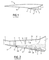
- Figure 1 schematically illustrates an aircraft equipped with a ramjet according to the invention.
- FIG. 2 represents, in schematic longitudinal section, an exemplary embodiment of said ramjet with geometry evolution of the invention.
- Figure 3 shows, in schematic longitudinal section, a alternative embodiment of said ramjet.
- the aircraft 1 shown in FIG. 1 is equipped, under its fuselage 1A in this embodiment, of a ramjet with evolutionary geometry, allowing it to fly in a wide range of speeds between numbers of Mach from 1-2 to 15-20.
- the ramjet 2 mainly comprises a body of structure 3, an oxidizer inlet 4, a device fuel injection 5, a combustion chamber 6 and an exhaust nozzle 7.
- the structural body 3 has longitudinally, approximately a form of conduit to rectangular or similar cross section, consisting of walls two by two opposite.
- the upper wall 3A is associated with the fuselage 1A of the aircraft, while the bottom wall 3B constitutes the lower surface of the ramjet.
- the other two side walls 3C are parallel to the plane of the figures.
- the oxidizer inlet 4 Upstream to downstream of the ramjet body according to its longitudinal direction, in the direction of flow of the jet or gas mixture symbolized by arrow F, are found the oxidizer inlet 4, in particular an air intake, the injection device 5 behind said entry, a chamber of combustion 6 in which the mixing is carried out oxidizer-fuel to be burned, and an exhaust nozzle 7 having a neck 8 with convergent-divergent geometry, intended to channel the gas jet produced towards the outside by mixing.
- the body 3 of the ramjet 2 has a evolutionary geometry at least in a transition zone 9 defined between a part of the combustion chamber 6 and part of the nozzle (neck) and allowing, as we have specified beforehand, to adapt the longitudinal section of the body 3, at least in this transition zone 9 (col 8), depending on the flight speed.
- combustion chamber 6 is subdivided into a upstream diffusion zone, where supersonic combustion begins, and a downstream chamber area, where combustion occurs supersonic, behind retractable flame catchers 10, and where the supersonic combustion ends.
- the structural body 3 of the ramjet 2 is provided, in this embodiment shown on the Figure 2, a controllable opening 11 formed in this case in the bottom wall 3B of the body and that is susceptible establish communication with the outside said combustion chamber 6 in order to introduce, when is operational, an outside air stream in the transition zone 9 of the body, flowing in the same direction F than the gas jet.
- This air stream V then allows to vary the geometry of the longitudinal section of the body, especially in the transition zone and modify the jet passage section accordingly gaseous passing through the interior of the structure body, as we will see it below.
- a flap 12 forming a retractable hatch closes the opening 11 to gradually discover it.
- This flap 12 is articulated around an axis 13 on the wall lower body 3B and its pivoting is controlled by a actuator not shown but of a type known per se.
- the axis of articulation 13 which is orthogonal to the longitudinal direction of the ramjet, is provided on the front edge 12A of the flap, facing the injection device 5, while its rear edge 12B is directed towards the transition zone.
- the flap 12 in the closed position of the flap 12, represented by a solid line in the figure 2, for which the opening 11 is completely closed, the flap 12 extends the wall 3B without discontinuity, and makes thus part wall office.
- flap 12 occupies, under the action of the actuator and the hinge pin 13, the position illustrated by a strong mixed line in FIG. 2, retraction towards the interior of the combustion 6 of the body 3.
- the flap 12 discovers the opening 11 which constitutes an air intake and through which is introduced an external air stream V.
- the geometry of the chamber 6 changes slightly, its cross section decreasing and that of the nozzle 7 substantially retains a neck 8 convergent-divergent, especially at the level of the transition 9.
- the outside air stream V which is low temperature and low pressure, thus acts as a "border natural "to vary the geometry of the body of structure, i.e. the gas jet at temperature and high pressures.
- flap 12 occupies the position indicated by a broken line on the Figure 2; as the shutter has entered the body, the cross section of the combustion chamber 6 decreases accordingly to tend to be almost constant, while the nozzle 8 retains a neck geometry convergent-divergent but certainly more flattened, due of the flow of the larger air stream V introduced in the body.
- the flap 12 occupies the position illustrated by a dashed line end, for which the geometry of the longitudinal section of the body 3 has a cross section substantially constant from combustion chamber 6 to neck 8 nozzle 7 which only has a divergent geometry.
- the flap 12 is substantially parallel to the upper wall 3A of the body, while the opening 11, then maximum, allows a large V air stream to enter the transition 9, said vein extending the plane of the flap 12 keeping the longitudinal section constant, up to diverge slightly after the nozzle neck.
- This configuration is advantageously used when the conditions of operation are such that the heat input achieved by combustion can be done in supersonic, without a thermal blocking phenomenon does not appear in the section substantially constant thus created (this is what determines if it's Mach 7 or more or less).
- this additional air stream constitutes a contribution of momentum, increasing the flow in the body, which can be beneficial to the thrust of the ramjet without necessarily increasing consumption.
- the ramjet trail decreases so that the friction, which has a major influence on performance as the Mach number increases, decreases on the lower wall of the structure body.
- the lower or lower part of the nozzle is advantageously cooled by the flow of air stream at low temperature, so that only the top wall undergoes intense heat fluxes.
- the dilution of the gas jet obtained at the nozzle outlet can be beneficial from the perspective of the radar signature which is scaled down.
- the evolutionary geometry of the structure body 3 is obtained by two openings 21, 22 formed in series in the wall lower body 3B and closable by controllable flaps, 23 and 24 respectively. More specifically, the first opening 21 communicates with the combustion chamber 6, while the second opening 22 opens directly in the transition zone 9 at the neck 8 nozzle 7, in the converging part of its geometry.
- part 23 of the first opening 21 is articulated by its rear edge 23A to the bottom wall 3B around a hinge pin 13, so that its front edge 23B pivots to reveal gradually the first opening 21.
- the same goes for the flap 24 of the second opening, articulated by its rear edge 24A at the wall of the nozzle neck, around a axis 13.
- the two components are again controlled by actuators not shown and the hinge pins 13 are parallel to each other and orthogonal to the direction length of the ramjet.
- the flap 23 is controlled to open respectively according to the positions illustrated by a line interrupted and by a thin mixed line, and let in opening 21, a corresponding external air stream which runs through the combustion chamber 6, the transition zone 9 and exits through the nozzle 7.
- the evolutionary geometry of the body 3 is substantially constant up to the level of the neck 8 of nozzle 7 for slightly diverge then. The higher the speed, the more the volume of the combustion chamber and the transition decreases until occupying a minimum volume for Mach numbers greater than 7 for example.
Description
La présente invention concerne un statoréacteur pour aéronef à vol supersonique et/ou hypersonique, destiné à fonctionner sur une large plage de vitesses qui, exprimée en nombres de Mach, peut être par exemple comprise entre 1-2 et 15-20.The present invention relates to a ramjet for aircraft supersonic and / or hypersonic flight, intended to operate over a wide range of speeds which, expressed in numbers of Mach, can for example be between 1-2 and 15-20.
On connaít déjà par la demande de brevet français 95 08417 un statoréacteur permettant de fonctionner dans une telle plage de vitesses, tout en conservant une efficacité maximale. Pour cela, il comprend :
- une entrée de comburant ;
- un dispositif d'injection de combustible ; et
- un corps de statoréacteur qui, d'une part, comprend une chambre de combustion dans laquelle est effectué le mélange comburant-combustible à brûler, et une tuyère d'échappement pour canaliser les gaz sortant de la chambre de combustion et qui, d'autre part, présente, au moins dans une zone de transition entre la chambre de combustion et la tuyère d'échappement, une géométrie évolutive permettant de passer progressivement d'une section longitudinale convergente puis divergente pour des vitesses correspondant à un nombre de Mach faible, à une section longitudinale approximativement constante puis divergente pour des vitesses correspondant à un nombre de Mach élevé.
- an oxidizer inlet;
- a fuel injection device; and
- a ramjet body which, on the one hand, comprises a combustion chamber in which the oxidant-fuel mixture to be burned is carried out, and an exhaust nozzle for channeling the gases leaving the combustion chamber and which, on the other hand part, presents, at least in a transition zone between the combustion chamber and the exhaust nozzle, an evolving geometry making it possible to pass progressively from a convergent then divergent longitudinal section for speeds corresponding to a low Mach number, at an approximately constant then divergent longitudinal section for speeds corresponding to a high Mach number.
Une telle géométrie évolutive de la section longitudinale du corps est obtenue, dans la réalisation décrite dans cette demande de brevet, par l'agencement de l'une des parois latérales du corps, sous la forme de plaques articulées entre elles autour d'axes transversaux à la direction longitudinale du statoréacteur, et situées au moins dans la zone de transition (col de tuyère). Ainsi, en fonction de la vitesse de vol choisie, on peut adapter la géométrie de la section longitudinale du corps, notamment dans la zone de transition, en amenant les plaques progressivement dans la position appropriée, ce qui permet de conserver pour la plage de vitesses indiquée, des conditions de vol optimales, en particulier une valeur de poussée maximale indépendamment des conditions externes (consommation de combustible, pression aérodynamique, profil du flux de comburant dans l'entrée correspondante). En d'autres termes, cela revient notamment à "effacer" le col de tuyère (géométrie convergente-divergente) existant à "faible" vitesse pour en définitive (nombre de Mach égal ou supérieur à environ 7) obtenir une section constante de la chambre de combustion, suivie par la section divergente de la tuyère d'échappement.Such an evolutionary geometry of the longitudinal section of the body is obtained, in the embodiment described in this patent application, by the arrangement of one of the walls side of the body, in the form of articulated plates between them around axes transverse to the direction longitudinal of the ramjet, and located at least in the transition zone (nozzle neck). So depending on the chosen flight speed, the geometry of the longitudinal section of the body, especially in the area of transition, gradually bringing the plates into the appropriate position, which allows to keep for the specified speed range, optimal flight conditions, in particular a maximum thrust value independently external conditions (fuel consumption, aerodynamic pressure, profile of the oxidizer flow in the corresponding entry). In other words, it comes down to in particular to "erase" the nozzle neck (convergent-divergent geometry) existing at "low" speed for in definitive (Mach number equal to or greater than about 7) obtain a constant section of the combustion chamber, followed by the divergent section of the exhaust nozzle.
Bien que techniquement opérationnelle, cette réalisation de la géométrie évolutive du corps peut être sujette, du point de vue de sa fiabilité dans des conditions extrêmes notamment de température, à des problèmes de bon fonctionnement au niveau des articulations des plaques. Des moyens de soufflage d'air peuvent être alors prévus pour remédier à ces inconvénients. Par ailleurs, l'ensemble de ces plaques articulées et des moyens de soufflage éventuels contribuent à augmenter la masse du statoréacteur, ce qui est préjudiciable.Although technically operational, this achievement of the evolutionary geometry of the body can be subject, from the point of its reliability in extreme conditions in particular temperature, malfunctions at the plate joints. Means of air supply can then be provided to remedy these disadvantages. Furthermore, all of these plates articulated and possible blowing means contribute to increase the mass of the ramjet, which is detrimental.
On connaít également de la demande de brevet français 1 110 011 un étranglement concentrique d'un jet localisé à la buse de sortie d'un statoréacteur au moyen d'une introduction des veines d'air extérieur à travers des ouvertures commandables.We also know from French patent application 1 110 011 a concentric throttling of a jet located at the outlet nozzle of a ramjet by means of an introduction of the outside air streams through controllable openings.
La présente invention a pour objet de proposer un statoréacteur dont la conception de la géométrie évolutive du corps s'affranchit des problèmes exposés ci-dessus.The object of the present invention is to propose a ramjet whose conception of the evolutionary geometry of body frees itself from the problems outlined above.
A cet effet, le statoréacteur du type énoncé préalablement est remarquable, selon l'invention, en ce que ledit corps du statoréacteur comporte au moins une ouverture commandable susceptible d'établir avec l'extérieur une communication avec ladite chambre de combustion, et permettant d'introduire une veine d'air extérieur dans ladite zone de transition. Ainsi, grâce à l'invention, la géométrie évolutive du corps est obtenue par l'introduction de ladite veine d'air extérieur dans la zone de transition du statoréacteur, sans avoir recours à des pièces mécaniques comme dans la précédente réalisation. En effet, cette veine qui forme un écoulement d'air à faible température et à basse pression, permet de modifier, notamment au niveau de la zone de transition (col de tuyère), la section longitudinale de passage du mélange gazeux comburant-combustible à température élevée et à haute pression circulant dans le corps, lorsqu'elle est introduite dans ce dernier. Cette veine diminue ainsi la section de passage du mélange gazeux en la conformant de façon appropriée. En fonction de la vitesse de vol de l'aéronef, on adapte la quantité d'air extérieur admise dans le corps du statoréacteur par l'ouverture commandable, pour conserver des conditions de vol optimales.For this purpose, the ramjet of the type previously stated is remarkable, according to the invention, in that said body of the ramjet has at least one controllable opening likely to establish communication with the outside with said combustion chamber, and making it possible to introduce an outside air stream in said transition zone. Thus, thanks to the invention, the evolutionary geometry of the body is obtained by the introduction of said outside air stream in the transition region of the ramjet, without use mechanical parts as in the previous one production. Indeed, this vein which forms a air flow at low temperature and low pressure, allows to modify, in particular in the area of transition (nozzle neck), the longitudinal section of passage of the oxidant-fuel gas mixture at temperature high and high pressure circulating in the body, when introduced into the latter. This vein thus decreases the cross section of the gas mixture in the conforming appropriately. Depending on the speed of flight of the aircraft, we adjust the amount of outside air admitted into the ramjet body through the opening controllable, to maintain optimal flight conditions.
De plus, cette solution à géométrie évolutive par veine d'air contribue à diminuer les contraintes thermiques apparaissant au niveau de la tuyère notamment et à réduire la masse du statoréacteur, comparativement à la solution antérieure.In addition, this solution with evolutionary geometry by vein air helps to reduce thermal stresses appearing in particular at the nozzle and to reduce the mass of the ramjet, compared to the solution anterior.
Par exemple, ladite ouverture est ménagée dans une paroi dudit corps, et un volet commandable est articulé, autour d'un axe, à ladite paroi pour obturer ladite ouverture lorsqu'il occupe une position fermée, et permettre le passage de ladite veine d'air extérieur à l'intérieur dudit corps, à travers ladite ouverture, lorsqu'il occupe une quelconque position ouverte.For example, said opening is formed in a wall of said body, and a controllable flap is articulated around an axis at said wall to close off said opening when in a closed position, and allow the passage of said outside air stream inside said body, through said opening, when it occupies a any open position.
Généralement, le corps de statoréacteur présente une forme de conduit à section transversale rectangulaire, constitué de parois deux à deux opposées. Dans ce cas, ladite ouverture est prévue dans la paroi inférieure ou intrados dudit corps. La paroi supérieure est alors associée au fuselage de l'aéronef.Generally, the ramjet body has a shape of duct with rectangular cross section, consisting of walls two by two opposite. In this case, said opening is provided in the lower wall or lower surface of said body. The upper wall is then associated with the fuselage of the aircraft.
En outre, l'axe d'articulation dudit volet est sensiblement orthogonal à la direction longitudinale dudit corps. Dans un premier mode de réalisation, ledit volet commandable peut être articulé par son bord avant à ladite paroi par l'intermédiaire dudit axe, ledit volet pivotant vers l'intérieur dudit corps pour laisser entrer ladite veine d'air extérieur dans ce dernier. Dans un second mode de réalisation, ledit volet commandable est alors articulé par son bord arrière à ladite paroi par l'intermédiaire dudit axe, ledit volet pivotant vers l'extérieur dudit corps pour laisser entrer ladite veine d'air extérieur dans ce dernier.In addition, the axis of articulation of said flap is substantially orthogonal to the longitudinal direction of said body. In one first embodiment, said controllable component can be articulated by its front edge to said wall via of said axis, said flap pivoting inwards said body to let in said outside air stream in this last. In a second embodiment, said the controllable flap is then articulated by its rear edge at said wall via said axis, said flap pivoting outward from said body to allow entry said outside air stream therein.
Par ailleurs, deux ouvertures commandables peuvent être ménagées dans ledit corps, une première communiquant avec ladite chambre de combustion, et une seconde communiquant avec ladite zone de transition. Des volets commandent lesdites ouvertures et sont articulés sur une paroi dudit corps autour d'axes respectifs. Ainsi, la seconde ouverture peut être utilisée pour amener une veine d'air dans la zone de transition pour des nombres de Mach faibles. Et la première ouverture est utilisée pour des nombres de Mach plus élevés afin de conformer, de façon appropriée, la géométrie de la section longitudinale dudit corps.In addition, two controllable openings can be formed in said body, a first communicating with said combustion chamber, and a second communicating with said transition zone. Shutters control said openings and are articulated on a wall of said body around respective axes. So the second opening can be used to bring an air stream into the area of transition for weak Mach numbers. And the first opening is used for Mach numbers higher in order to appropriately conform the geometry of the longitudinal section of said body.
Les figures du dessin annexé feront bien comprendre comment l'invention peut être réalisée. Sur ces figures, des références identiques désignent des éléments semblables.The figures in the accompanying drawing will make it clear how the invention can be realized. In these figures, references identical denote similar elements.
La figure 1 illustre schématiquement un aéronef équipé d'un statoréacteur conforme à l'invention. Figure 1 schematically illustrates an aircraft equipped with a ramjet according to the invention.
La figure 2 représente, en coupe longitudinale schématique, un exemple de réalisation dudit statoréacteur à géométrie évolutive de l'invention.FIG. 2 represents, in schematic longitudinal section, an exemplary embodiment of said ramjet with geometry evolution of the invention.
La figure 3 montre, en coupe longitudinale schématique, une variante de réalisation dudit statoréacteur.Figure 3 shows, in schematic longitudinal section, a alternative embodiment of said ramjet.
L'aéronef 1 montré sur la figure 1 est équipé, sous son
fuselage 1A dans cet exemple de réalisation, d'un statoréacteur
à géométrie évolutive, lui permettant de voler dans
une large plage de vitesses comprise entre des nombres de
Mach de 1-2 à 15-20.The aircraft 1 shown in FIG. 1 is equipped, under its
Le statoréacteur 2 comprend principalement un corps de
structure 3, une entrée de comburant 4, un dispositif
d'injection de combustible 5, une chambre à combustion 6 et
une tuyère d'échappement 7. En particulier, dans l'exemple
représenté sur la figure 2, le corps de structure 3 présente
longitudinalement, approximativement une forme de conduit à
section transversale rectangulaire ou analogue, constitué de
parois deux à deux opposées. Dans l'exemple illustré, la
paroi supérieure 3A est associée au fuselage 1A de l'aéronef,
tandis que la paroi inférieure 3B constitue l'intrados
du statoréacteur. Les deux autres parois latérales 3C sont
parallèles au plan des figures.The ramjet 2 mainly comprises a body of
structure 3, an
De l'amont vers l'aval du corps de statoréacteur selon sa
direction longitudinale, dans le sens d'écoulement du jet ou
mélange gazeux symbolisé par la flèche F, se trouvent
l'entrée de comburant 4 notamment une prise d'air, le
dispositif d'injection 5 derrière ladite entrée, une chambre
de combustion 6 dans laquelle est effectué le mélange
comburant-combustible à brûler, et une tuyère d'échappement
7 présentant un col 8 à géométrie convergente-divergente,
destinée à canaliser vers l'extérieur le jet gazeux produit
par le mélange. Upstream to downstream of the ramjet body according to its
longitudinal direction, in the direction of flow of the jet or
gas mixture symbolized by arrow F, are found
the
Par ailleurs, le corps 3 du statoréacteur 2 présente une
géométrie évolutive au moins dans une zone de transition 9
définie entre une partie de la chambre de combustion 6 et
une partie de la tuyère (col) et permettant, comme on l'a
précisé préalablement, d'adapter la section longitudinale du
corps 3, au moins dans cette zone de transition 9 (col 8),
en fonction de la vitesse de vol.Furthermore, the body 3 of the ramjet 2 has a
evolutionary geometry at least in a
En outre, la chambre de combustion 6 se subdivise en une
zone de diffusion amont, où commence la combustion supersonique,
et une zone de chambre aval, où se produit la combustion
supersonique, derrière des accroche-flammes rétractables
10, et où se termine la combustion supersonique. Le
dispositif d'injection 5, constitué d'injecteurs, répartit
le combustible dans tout le volume de la chambre. Comme
combustible à utiliser en fonction du nombre de Mach souhaité,
on se reportera à la demande de brevet français précitée.In addition, the
Selon l'invention, le corps de structure 3 du statoréacteur
2 est pourvu, dans cet exemple de réalisation montré sur la
figure 2, d'une ouverture commandable 11 ménagée, dans ce
cas, dans la paroi inférieure 3B du corps et qui est susceptible
d'établir avec l'extérieur une communication avec
ladite chambre de combustion 6 afin d'introduire, lorsqu'elle
est opérationnelle, une veine d'air extérieur dans
la zone de transition 9 du corps, s'écoulant dans le même
sens F que le jet gazeux. Cette veine d'air V permet alors
de faire varier la géométrie de la section longitudinale du
corps, notamment au niveau de la zone de transition et de
modifier, en conséquence, la section de passage du jet
gazeux traversant l'intérieur du corps de structure, comme
on le verra ci-après.According to the invention, the structural body 3 of the ramjet
2 is provided, in this embodiment shown on the
Figure 2, a
En particulier, un volet 12 formant trappe escamotable,
obture l'ouverture 11 pour la découvrir progressivement. Ce
volet 12 est articulé autour d'un axe 13 sur la paroi
inférieure 3B du corps et son pivotement est commandé par un
actionneur non représenté mais d'un type connu en soi. Dans
cet exemple, l'axe d'articulation 13 qui est orthogonal à la
direction longitudinale du statoréacteur, est prévu sur le
bord avant 12A du volet, tourné vers le dispositif d'injection
5, tandis que son bord arrière 12B est dirigé vers la
zone de transition. Bien évidemment, dans la position fermée
du volet 12, représentée par un trait continu sur la figure
2, pour laquelle l'ouverture 11 est totalement obturée, le
volet 12 prolonge la paroi 3B sans discontinuité, et fait
ainsi office de partie de paroi.In particular, a
A cette position fermée du volet 12 (en trait continu),
correspond une vitesse de vol comprise dans la plage de Mach
1-2 pour laquelle le volume (ou la hauteur) de la chambre de
combustion 6 est maximale (section transversale de passage
maximale), le statoréacteur 1 se terminant par une tuyère 7
à col ouvert à géométrie convergente-divergente.At this closed position of the flap 12 (in solid lines),
corresponds to a flight speed within the Mach range
1-2 for which the volume (or height) of the
Pour une vitesse de vol de l'ordre de 2,5 Mach, le volet 12
occupe, sous l'action de l'actionneur et de l'axe d'articulation
13, la position illustrée par un trait mixte fort
sur la figure 2, rentrée vers l'intérieur de la chambre de
combustion 6 du corps 3. Le volet 12 découvre l'ouverture 11
qui constitue une prise d'air et à travers laquelle s'introduit
une veine d'air extérieur V. Celle-ci, canalisée par le
volet 12, s'écoule en direction de la zone de transition 9,
en obligeant le jet gazeux issu du mélange comburant-combustible
à prendre une configuration de section transversale
réduite le long de la section longitudinale depuis le
volet 12, qui participe aussi à la configuration de la
nouvelle géométrie du jet gazeux, jusqu'à la sortie de la
tuyère 7. Dans cette position, la géométrie de la chambre 6
change légèrement, sa section transversale diminuant et
celle de la tuyère 7 conserve sensiblement un col 8
convergent-divergent, notamment au niveau de la zone de
transition 9. La veine d'air extérieur V, qui est à basse
température et basse pression, fait ainsi office de "frontière
naturelle" pour varier la géométrie du corps de
structure, c'est-à-dire le jet gazeux à température et
pression élevées.For a flight speed of around 2.5 Mach, flap 12
occupies, under the action of the actuator and the
Pour une vitesse de vol de 6 Mach par exemple, le volet 12
occupe la position indiquée par un trait interrompu sur la
figure 2 ; comme le volet est davantage rentré dans le
corps, la section transversale de la chambre de combustion 6
diminue en conséquence pour tendre à être presque constante,
tandis que la tuyère 8 conserve une géométrie de col
convergente-divergente mais certes plus aplatie, en raison
de l'écoulement de la veine d'air V plus importante introduite
dans le corps.For a flight speed of 6 Mach for example,
En ce qui concerne le fonctionnement des accroche-flammes 10
et du dispositif d'injection de combustible 5 à ces différentes
vitesses et autres, on se reportera à ladite demande
de brevet français précitée.Regarding the operation of the
Pour une vitesse de vol supérieure à 7 Mach par exemple, le
volet 12 occupe la position illustrée par un trait mixte
fin, pour laquelle la géométrie de la section longitudinale
du corps 3 présente une section transversale sensiblement
constante depuis la chambre de combustion 6 jusqu'au col 8
de tuyère 7 qui ne possède plus qu'une géométrie divergente.
Le volet 12 est sensiblement parallèle à la paroi supérieure
3A du corps, tandis que l'ouverture 11, alors maximale,
laisse entrer une veine d'air V importante dans la zone de
transition 9, ladite veine prolongeant le plan du volet 12
en maintenant la section longitudinale constante, jusqu'à
diverger légèrement après le col de tuyère. Cette configuration
est utilisée avantageusement lorsque les conditions de
fonctionnement sont telles que l'apport de chaleur réalisé
par la combustion peut se faire en supersonique, sans qu'un
phénomène de blocage thermique n'apparaisse dans la section
sensiblement constante ainsi créée (c'est ce qui détermine
si c'est Mach 7 ou plus ou moins).For a flight speed greater than 7 Mach for example, the
Bien qu'une telle géométrie variable du corps de structure 3 dudit statoréacteur, par l'introduction d'une veine d'air, permette d'optimiser les différentes phases de vol de l'aéronef et cela, sur une plage de Mach et de conditions de vol (altitude, incidence, accélération ou croisière) importantes, elle présente également d'autres avantages appréciables.Although such a variable geometry of the structural body 3 of said ramjet, by the introduction of an air stream, optimizes the different flight phases of the aircraft and this, over a range of Mach and conditions of significant flight (altitude, incidence, acceleration or cruise), it also has other appreciable advantages.
En effet, cette veine d'air supplémentaire constitue un apport de quantité de mouvement, augmentant le débit dans le corps, ce qui peut être profitable à la poussée du statoréacteur sans augmenter nécessairement la consommation. De plus, la traínée du statoréacteur diminue si bien que le frottement, qui a une influence importante sur les performances en fonction que le nombre de Mach augmente, diminue sur la paroi inférieure du corps de structure. Par ailleurs, la partie inférieure ou basse de la tuyère est avantageusement refroidie par l'écoulement de la veine d'air à basse température, de sorte que seule la paroi supérieure subit des flux thermiques intenses. On peut également noter que la dilution du jet gazeux obtenue en sortie de tuyère peut être bénéfique du point de vue de la signature radar qui est réduite.Indeed, this additional air stream constitutes a contribution of momentum, increasing the flow in the body, which can be beneficial to the thrust of the ramjet without necessarily increasing consumption. Of more, the ramjet trail decreases so that the friction, which has a major influence on performance as the Mach number increases, decreases on the lower wall of the structure body. Otherwise, the lower or lower part of the nozzle is advantageously cooled by the flow of air stream at low temperature, so that only the top wall undergoes intense heat fluxes. It can also be noted that the dilution of the gas jet obtained at the nozzle outlet can be beneficial from the perspective of the radar signature which is scaled down.
Dans la variante de réalisation montrée sur la figure 3, la
géométrie évolutive du corps de structure 3 est obtenue par
deux ouvertures 21, 22 ménagées en série dans la paroi
inférieure 3B du corps et obturables par des volets commandables,
respectivement 23 et 24. Plus particulièrement, la
première ouverture 21 communique avec la chambre de combustion
6, tandis que la seconde ouverture 22 débouche
directement dans la zone de transition 9 au niveau du col 8
de tuyère 7, dans la partie convergente de sa géométrie.In the alternative embodiment shown in FIG. 3, the
evolutionary geometry of the structure body 3 is obtained by
two
Contrairement à la réalisation précédente, le volet 23 de la
première ouverture 21 est articulé par son bord arrière 23A
à la paroi inférieure 3B autour d'un axe d'articulation 13,
de sorte que son bord avant 23B pivote pour découvrir
progressivement la première ouverture 21. Il en va de même
pour le volet 24 de la seconde ouverture, articulé par son
bord arrière 24A à la paroi du col de tuyère, autour d'un
axe 13. Les deux volets sont là aussi commandés par des
actionneurs non représentés et les axes d'articulation 13
sont parallèles entre eux et orthogonaux à la direction
longitudinale du statoréacteur.Unlike the previous embodiment,
Le fonctionnement de cette variante de réalisation est semblable à celui décrit en regard de la figure 2.The operation of this alternative embodiment is similar to that described with reference to Figure 2.
Pour des vitesses de vol de l'ordre de 2,5 Mach, seul le
volet 24 est actionné permettant de découvrir, de façon
appropriée pour cette vitesse, la seconde ouverture 22 et de
faire pénétrer une veine d'air extérieur V représentée par
un trait mixte fort, directement dans le col 8 de tuyère 7,
de façon à modifier, à cet endroit de la zone de transition
9, le jet gazeux issu de la combustion. Le volet 23 obture
quant à lui la première ouverture 21.For flight speeds of the order of 2.5 Mach, only the
Pour des vitesses de vol de l'ordre de 6 Mach et supérieures
à 7 Mach par exemple, le volet 23 est commandé pour s'ouvrir
respectivement selon les positions illustrées par un trait
interrompu et par un trait mixte fin, et laisser entrer par
l'ouverture 21, une veine d'air extérieur correspondante qui
parcourt la chambre de combustion 6, la zone de transition 9
et sort par la tuyère 7. Pour une vitesse de vol d'au moins
7 Mach, la géométrie évolutive du corps 3 est sensiblement
constante jusqu'au niveau du col 8 de tuyère 7 pour
légèrement diverger ensuite. Plus la vitesse augmente, plus
le volume de la chambre de combustion et de la zone de
transition diminue jusqu'à occuper un volume minimal pour
des nombres de Mach supérieurs à 7 par exemple.For flight speeds of the order of 6 Mach and above
at 7 Mach for example, the
Claims (8)
- A ramjet for supersonic and/or hypersonic aircraft, designed to operate over a wide range of speeds, comprising:characterized in that said ramjet body (3) comprises at least one controllable opening (11) adapted to establish communication between said combustion chamber and the exterior and to introduce of an exterior air stream into said transition area (9) so as to generate said variable geometry.an inlet (4) for a combustion supporting gas;a fuel injection device (5); anda ramjet body (3) which comprises a combustion chamber (6) in which said combustion supporting gas is mixed with a fuel to be burned and an exhaust nozzle (7) to channel the gases leaving said combustion chamber and which has, at least in a transition area (9) between said combustion chamber and said exhaust nozzle, a variable geometry progressively varying from a convergent then divergent longitudinal section for speeds corresponding to a low Mach number to an approximately constant and then divergent longitudinal section for speeds corresponding to a high Mach number,
- The ramjet claimed in claim 1 characterized in that said opening (11, 21, 22) is formed in a wall of said body (3) and in that a controllable flap (12, 23, 24) is hinged to said wall about an axis to close off said opening when it occupies a closed position and to enable said exterior air stream to flow into the interior of said body through said opening when it occupies any open position.
- The ramjet claimed in the preceding claim of the type in which said body has the general shape of a rectangular cross-section duct made up of opposite pairs of walls, characterized in that said opening (11) is provided in the bottom wall or intrados (3B) in the normal flight direction of said body.
- The ramjet claimed in either of claims 2 and 3 characterized in that the hinge axis (13) of said flap is substantially orthogonal to the longitudinal direction of said body (3).
- The ramjet claimed in any one of claims 2 to 4 characterized in that said controllable flap (12) is hinged to said wall about said axis at its upstream edge and pivots towards the interior of said body to allow said exterior air stream to enter thereinto.
- The ramjet claimed in any one of claims 2 to 4 characterized in that said controllable flap (23, 24) is hinged to said wall about said axis at its downstream edge (23A, 24A) and pivots towards the exterior of said body to allow said exterior air stream to enter thereinto.
- The ramjet claimed in any one of the preceding claims characterized in that two controllable openings (21, 22) are formed in said body (3) , a first (21) of them communicating with said combustion chamber (6) and a second (22) of them communicating with said transition area (9).
- The ramjet claimed in the preceding claim characterized in that flaps (23, 24) control said openings and are hinged to a wall (3B) of said body about respective axes (13).
Applications Claiming Priority (2)
| Application Number | Priority Date | Filing Date | Title |
|---|---|---|---|
| FR9602603 | 1996-03-01 | ||
| FR9602603A FR2745606B1 (en) | 1996-03-01 | 1996-03-01 | STATOREACTOR WITH EVOLUTIVE GEOMETRY FOR AIRCRAFT |
Publications (2)
| Publication Number | Publication Date |
|---|---|
| EP0793011A1 EP0793011A1 (en) | 1997-09-03 |
| EP0793011B1 true EP0793011B1 (en) | 2001-04-18 |
Family
ID=9489759
Family Applications (1)
| Application Number | Title | Priority Date | Filing Date |
|---|---|---|---|
| EP97400336A Expired - Lifetime EP0793011B1 (en) | 1996-03-01 | 1997-02-14 | Ramjet with variable geometry |
Country Status (8)
| Country | Link |
|---|---|
| US (1) | US5894722A (en) |
| EP (1) | EP0793011B1 (en) |
| JP (1) | JP3930599B2 (en) |
| CA (1) | CA2198419C (en) |
| DE (1) | DE69704585T2 (en) |
| ES (1) | ES2155970T3 (en) |
| FR (1) | FR2745606B1 (en) |
| RU (1) | RU2125172C1 (en) |
Families Citing this family (6)
| Publication number | Priority date | Publication date | Assignee | Title |
|---|---|---|---|---|
| US7216474B2 (en) * | 2004-02-19 | 2007-05-15 | Aerojet-General Corporation | Integrated air inlet system for multi-propulsion aircraft engines |
| US20140331682A1 (en) * | 2012-11-08 | 2014-11-13 | Mark Bovankovich | High-speed-launch ramjet booster |
| US9656760B2 (en) * | 2013-11-07 | 2017-05-23 | Sikorsky Aircraft Corporation | Variable geometry helicopter engine inlet |
| CN104863715B (en) * | 2015-04-16 | 2016-08-17 | 南京航空航天大学 | A kind of rectangular inlet binary hypersonic change geometry air intake duct, its method for designing and method of work |
| CN112627990B (en) * | 2020-12-23 | 2021-11-19 | 华中科技大学 | Flow passage adjusting structure of direct-drive combined engine and control method thereof |
| US11434018B1 (en) * | 2021-11-27 | 2022-09-06 | Airbus Defence and Space GmbH | Switchable air inlet device for engine air |
Family Cites Families (6)
| Publication number | Priority date | Publication date | Assignee | Title |
|---|---|---|---|---|
| FR1110011A (en) * | 1954-08-20 | 1956-02-06 | Improvements made to stato-reactors for aerodynes, in particular those for flight at supersonic speed | |
| US3143852A (en) * | 1961-09-08 | 1964-08-11 | John M Alderson | Ram jet engine |
| US3279194A (en) * | 1962-08-14 | 1966-10-18 | Garrett Corp | Aerothermodynamic duct and control means therefor |
| FR1496091A (en) * | 1966-04-20 | 1967-09-29 | Snecma | Ejection nozzle for thrusters with several motor flows, in particular with two motor flows |
| GB2222635B (en) * | 1987-10-24 | 1992-05-27 | British Aerospace | Propulsion units for aerospace vehicles |
| US5054288A (en) * | 1988-10-24 | 1991-10-08 | The Boeing Company | Bypass duct for a hypersonic propulsion system |
-
1996
- 1996-03-01 FR FR9602603A patent/FR2745606B1/en not_active Expired - Lifetime
-
1997
- 1997-02-14 ES ES97400336T patent/ES2155970T3/en not_active Expired - Lifetime
- 1997-02-14 DE DE69704585T patent/DE69704585T2/en not_active Expired - Lifetime
- 1997-02-14 EP EP97400336A patent/EP0793011B1/en not_active Expired - Lifetime
- 1997-02-25 CA CA002198419A patent/CA2198419C/en not_active Expired - Lifetime
- 1997-02-27 JP JP04392797A patent/JP3930599B2/en not_active Expired - Lifetime
- 1997-02-28 RU RU97103047A patent/RU2125172C1/en active IP Right Revival
- 1997-02-28 US US08/808,574 patent/US5894722A/en not_active Expired - Fee Related
Also Published As
| Publication number | Publication date |
|---|---|
| FR2745606A1 (en) | 1997-09-05 |
| JP3930599B2 (en) | 2007-06-13 |
| DE69704585T2 (en) | 2001-08-30 |
| JPH09324701A (en) | 1997-12-16 |
| FR2745606B1 (en) | 1998-04-30 |
| EP0793011A1 (en) | 1997-09-03 |
| CA2198419A1 (en) | 1997-09-01 |
| US5894722A (en) | 1999-04-20 |
| RU2125172C1 (en) | 1999-01-20 |
| DE69704585D1 (en) | 2001-05-23 |
| CA2198419C (en) | 2005-02-22 |
| ES2155970T3 (en) | 2001-06-01 |
Similar Documents
| Publication | Publication Date | Title |
|---|---|---|
| EP0646525B1 (en) | Bidimensional supersonic and hypersonic air intake with three mobile ramps for the combustion air of an aircraft engine | |
| EP0434565B1 (en) | Versatile combined propulsion engine for aeroplane or space shuttle | |
| EP0506516B1 (en) | Combustion air control device for turbomachine combustor | |
| FR2826054A1 (en) | VARIABLE CYCLE PROPULSION DEVICE BY GAS DIVERSION FOR SUPERSONIC AIRCRAFT AND OPERATING METHOD | |
| FR2929998A1 (en) | DOUBLE FLOW TURBOREACTOR NACELLE | |
| FR2661715A1 (en) | EXHAUST ASSEMBLY FOR MOTORS OF HIGH-SPEED CIVIL TRANSPORT AIRPLANES. | |
| EP3325778B1 (en) | Aircraft comprising a rear fairing propulsion system with inlet stator comprising a blowing function | |
| FR2924408A1 (en) | TURBOREACTOR NACELLE AND METHOD FOR CONTROLLING DECOLUTION IN A TURBOREACTEUR NACELLE | |
| EP0094296B1 (en) | Device for regulating the pressure drop across at least one flux of a multiflux turbine | |
| FR2651020A1 (en) | EXHAUST TUBE WITH INTEGRAL TRANSITION AND CONVERGENT SECTION | |
| EP0076192B1 (en) | Jet engine, especially for a supersonic aircraft | |
| FR2660972A1 (en) | PUSH NOZZLE FOR A HYPERSONIC REACTOR. | |
| FR2658868A1 (en) | SUPERSONIC COMBUSTION STATOREACTOR ENGINE AND METHOD OF OPERATING SAME. | |
| EP0214003A1 (en) | Fuel injection nozzle with an enlarged screen for the combustion chamber of a gas turbine | |
| EP1808593A1 (en) | Variable-section flow mixer for a double-flow jet engine of a supersonic airplane | |
| EP0326448A1 (en) | Mixing device with a variable section for the different jets of a jet engine | |
| EP0806563A1 (en) | Doors with deflector vanes for a thrust reverser of a turbofan engine | |
| CA2619561C (en) | Variable section flow mixer for dual flow turbojet for supersonic aircraft | |
| EP1020631B1 (en) | Ejection nozzle for turbojet with integrated thrust reverser | |
| EP0793011B1 (en) | Ramjet with variable geometry | |
| CA2180502C (en) | Ramjet engine for supersonic and/or hypersonic aircraft | |
| FR2658248A1 (en) | GAS-STATOREACTOR TURBINE ENGINE ASSEMBLY HAVING A VARIABLE AIR INLET | |
| EP0515263A1 (en) | Thrust reverser for high by-pass ratio turbofan | |
| WO2017013362A1 (en) | Aircraft propulsion assembly comprising a thrust reverser | |
| FR2653177A1 (en) | TURBO STATOREACTOR EQUIPPED WITH AIRCRAFT FOR SUB AND / OR HYPERSONIC FLIGHT. |
Legal Events
| Date | Code | Title | Description |
|---|---|---|---|
| PUAI | Public reference made under article 153(3) epc to a published international application that has entered the european phase |
Free format text: ORIGINAL CODE: 0009012 |
|
| AK | Designated contracting states |
Kind code of ref document: A1 Designated state(s): BE DE ES GB IT NL SE |
|
| 17P | Request for examination filed |
Effective date: 19970918 |
|
| 17Q | First examination report despatched |
Effective date: 19990525 |
|
| GRAG | Despatch of communication of intention to grant |
Free format text: ORIGINAL CODE: EPIDOS AGRA |
|
| RAP1 | Party data changed (applicant data changed or rights of an application transferred) |
Owner name: AEROSPATIALE MATRA |
|
| GRAG | Despatch of communication of intention to grant |
Free format text: ORIGINAL CODE: EPIDOS AGRA |
|
| GRAH | Despatch of communication of intention to grant a patent |
Free format text: ORIGINAL CODE: EPIDOS IGRA |
|
| GRAH | Despatch of communication of intention to grant a patent |
Free format text: ORIGINAL CODE: EPIDOS IGRA |
|
| GRAA | (expected) grant |
Free format text: ORIGINAL CODE: 0009210 |
|
| AK | Designated contracting states |
Kind code of ref document: B1 Designated state(s): BE DE ES GB IT NL SE |
|
| GBT | Gb: translation of ep patent filed (gb section 77(6)(a)/1977) |
Effective date: 20010418 |
|
| ITF | It: translation for a ep patent filed |
Owner name: MODIANO & ASSOCIATI S.R.L. |
|
| REF | Corresponds to: |
Ref document number: 69704585 Country of ref document: DE Date of ref document: 20010523 |
|
| REG | Reference to a national code |
Ref country code: ES Ref legal event code: FG2A Ref document number: 2155970 Country of ref document: ES Kind code of ref document: T3 |
|
| REG | Reference to a national code |
Ref country code: GB Ref legal event code: IF02 |
|
| PLBE | No opposition filed within time limit |
Free format text: ORIGINAL CODE: 0009261 |
|
| STAA | Information on the status of an ep patent application or granted ep patent |
Free format text: STATUS: NO OPPOSITION FILED WITHIN TIME LIMIT |
|
| 26N | No opposition filed | ||
| EUG | Se: european patent has lapsed | ||
| REG | Reference to a national code |
Ref country code: SE Ref legal event code: RINS Effective date: 20110725 |
|
| PG25 | Lapsed in a contracting state [announced via postgrant information from national office to epo] |
Ref country code: SE Free format text: LAPSE BECAUSE OF NON-PAYMENT OF DUE FEES Effective date: 20100215 |
|
| PGRI | Patent reinstated in contracting state [announced from national office to epo] |
Ref country code: SE Effective date: 20110725 |
|
| PGFP | Annual fee paid to national office [announced via postgrant information from national office to epo] |
Ref country code: NL Payment date: 20160113 Year of fee payment: 20 |
|
| PGFP | Annual fee paid to national office [announced via postgrant information from national office to epo] |
Ref country code: IT Payment date: 20160212 Year of fee payment: 20 Ref country code: ES Payment date: 20160301 Year of fee payment: 20 Ref country code: DE Payment date: 20160212 Year of fee payment: 20 |
|
| PGFP | Annual fee paid to national office [announced via postgrant information from national office to epo] |
Ref country code: BE Payment date: 20160224 Year of fee payment: 20 Ref country code: SE Payment date: 20160212 Year of fee payment: 20 Ref country code: GB Payment date: 20160216 Year of fee payment: 20 |
|
| REG | Reference to a national code |
Ref country code: DE Ref legal event code: R071 Ref document number: 69704585 Country of ref document: DE |
|
| REG | Reference to a national code |
Ref country code: NL Ref legal event code: MK Effective date: 20170213 |
|
| REG | Reference to a national code |
Ref country code: GB Ref legal event code: PE20 Expiry date: 20170213 |
|
| REG | Reference to a national code |
Ref country code: SE Ref legal event code: EUG |
|
| REG | Reference to a national code |
Ref country code: ES Ref legal event code: FD2A Effective date: 20170526 |
|
| PG25 | Lapsed in a contracting state [announced via postgrant information from national office to epo] |
Ref country code: GB Free format text: LAPSE BECAUSE OF EXPIRATION OF PROTECTION Effective date: 20170213 |
|
| PG25 | Lapsed in a contracting state [announced via postgrant information from national office to epo] |
Ref country code: ES Free format text: LAPSE BECAUSE OF EXPIRATION OF PROTECTION Effective date: 20170215 |