EP0753394A2 - Procédé pour la fabrication en continu de panneaux sandwich pour échafaudage et pour coffrage et produits par le procédé - Google Patents
Procédé pour la fabrication en continu de panneaux sandwich pour échafaudage et pour coffrage et produits par le procédé Download PDFInfo
- Publication number
- EP0753394A2 EP0753394A2 EP96111184A EP96111184A EP0753394A2 EP 0753394 A2 EP0753394 A2 EP 0753394A2 EP 96111184 A EP96111184 A EP 96111184A EP 96111184 A EP96111184 A EP 96111184A EP 0753394 A2 EP0753394 A2 EP 0753394A2
- Authority
- EP
- European Patent Office
- Prior art keywords
- board
- continuous
- formation
- mold
- layered
- Prior art date
- Legal status (The legal status is an assumption and is not a legal conclusion. Google has not performed a legal analysis and makes no representation as to the accuracy of the status listed.)
- Withdrawn
Links
- 238000000034 method Methods 0.000 title claims abstract description 48
- 238000009415 formwork Methods 0.000 title claims abstract description 13
- 238000010924 continuous production Methods 0.000 title claims abstract description 5
- 229920005989 resin Polymers 0.000 claims abstract description 40
- 239000011347 resin Substances 0.000 claims abstract description 40
- 230000002787 reinforcement Effects 0.000 claims abstract description 39
- 239000000463 material Substances 0.000 claims abstract description 27
- 238000006116 polymerization reaction Methods 0.000 claims abstract description 27
- 230000015572 biosynthetic process Effects 0.000 claims abstract description 23
- 239000000109 continuous material Substances 0.000 claims abstract description 15
- 239000000835 fiber Substances 0.000 claims abstract description 7
- 239000011152 fibreglass Substances 0.000 claims abstract description 6
- 230000003014 reinforcing effect Effects 0.000 claims abstract description 3
- 239000010410 layer Substances 0.000 claims description 52
- 229920002635 polyurethane Polymers 0.000 claims description 11
- 239000004814 polyurethane Substances 0.000 claims description 11
- 238000011144 upstream manufacturing Methods 0.000 claims description 6
- 238000007789 sealing Methods 0.000 claims description 5
- VTYYLEPIZMXCLO-UHFFFAOYSA-L Calcium carbonate Chemical compound [Ca+2].[O-]C([O-])=O VTYYLEPIZMXCLO-UHFFFAOYSA-L 0.000 claims description 4
- 240000007182 Ochroma pyramidale Species 0.000 claims description 4
- 241000264877 Hippospongia communis Species 0.000 claims description 3
- 229920000728 polyester Polymers 0.000 claims description 3
- 239000002356 single layer Substances 0.000 claims description 3
- 239000002023 wood Substances 0.000 claims description 3
- 125000001931 aliphatic group Chemical group 0.000 claims description 2
- 229910000019 calcium carbonate Inorganic materials 0.000 claims description 2
- 239000000203 mixture Substances 0.000 claims description 2
- 150000005846 sugar alcohols Polymers 0.000 claims description 2
- 239000004094 surface-active agent Substances 0.000 claims description 2
- 230000006835 compression Effects 0.000 claims 1
- 238000007906 compression Methods 0.000 claims 1
- 238000003780 insertion Methods 0.000 claims 1
- 230000037431 insertion Effects 0.000 claims 1
- 241000196324 Embryophyta Species 0.000 description 11
- 238000004519 manufacturing process Methods 0.000 description 8
- 239000003365 glass fiber Substances 0.000 description 6
- 238000005470 impregnation Methods 0.000 description 5
- 239000012779 reinforcing material Substances 0.000 description 5
- OKTJSMMVPCPJKN-UHFFFAOYSA-N Carbon Chemical compound [C] OKTJSMMVPCPJKN-UHFFFAOYSA-N 0.000 description 3
- 238000004873 anchoring Methods 0.000 description 3
- 229910052799 carbon Inorganic materials 0.000 description 3
- 239000003795 chemical substances by application Substances 0.000 description 3
- 238000010586 diagram Methods 0.000 description 3
- 229910052500 inorganic mineral Inorganic materials 0.000 description 3
- 239000011707 mineral Substances 0.000 description 3
- 229920005749 polyurethane resin Polymers 0.000 description 3
- 235000013311 vegetables Nutrition 0.000 description 3
- 238000010438 heat treatment Methods 0.000 description 2
- 239000007788 liquid Substances 0.000 description 2
- 239000002184 metal Substances 0.000 description 2
- 238000010008 shearing Methods 0.000 description 2
- 238000005299 abrasion Methods 0.000 description 1
- 238000004026 adhesive bonding Methods 0.000 description 1
- 239000007767 bonding agent Substances 0.000 description 1
- 230000001419 dependent effect Effects 0.000 description 1
- 239000012467 final product Substances 0.000 description 1
- 239000011521 glass Substances 0.000 description 1
- 239000003292 glue Substances 0.000 description 1
- 238000007654 immersion Methods 0.000 description 1
- 230000008595 infiltration Effects 0.000 description 1
- 238000001764 infiltration Methods 0.000 description 1
- 238000002347 injection Methods 0.000 description 1
- 239000007924 injection Substances 0.000 description 1
- 239000002245 particle Substances 0.000 description 1
- 229920003023 plastic Polymers 0.000 description 1
- 239000004033 plastic Substances 0.000 description 1
- 230000000379 polymerizing effect Effects 0.000 description 1
- 238000002360 preparation method Methods 0.000 description 1
- 238000004064 recycling Methods 0.000 description 1
- 239000004576 sand Substances 0.000 description 1
- 239000000243 solution Substances 0.000 description 1
- 238000005507 spraying Methods 0.000 description 1
- 230000008961 swelling Effects 0.000 description 1
Images

Classifications
-
- B—PERFORMING OPERATIONS; TRANSPORTING
- B29—WORKING OF PLASTICS; WORKING OF SUBSTANCES IN A PLASTIC STATE IN GENERAL
- B29C—SHAPING OR JOINING OF PLASTICS; SHAPING OF MATERIAL IN A PLASTIC STATE, NOT OTHERWISE PROVIDED FOR; AFTER-TREATMENT OF THE SHAPED PRODUCTS, e.g. REPAIRING
- B29C70/00—Shaping composites, i.e. plastics material comprising reinforcements, fillers or preformed parts, e.g. inserts
- B29C70/04—Shaping composites, i.e. plastics material comprising reinforcements, fillers or preformed parts, e.g. inserts comprising reinforcements only, e.g. self-reinforcing plastics
- B29C70/28—Shaping operations therefor
- B29C70/54—Component parts, details or accessories; Auxiliary operations, e.g. feeding or storage of prepregs or SMC after impregnation or during ageing
- B29C70/545—Perforating, cutting or machining during or after moulding
-
- B—PERFORMING OPERATIONS; TRANSPORTING
- B29—WORKING OF PLASTICS; WORKING OF SUBSTANCES IN A PLASTIC STATE IN GENERAL
- B29C—SHAPING OR JOINING OF PLASTICS; SHAPING OF MATERIAL IN A PLASTIC STATE, NOT OTHERWISE PROVIDED FOR; AFTER-TREATMENT OF THE SHAPED PRODUCTS, e.g. REPAIRING
- B29C70/00—Shaping composites, i.e. plastics material comprising reinforcements, fillers or preformed parts, e.g. inserts
- B29C70/04—Shaping composites, i.e. plastics material comprising reinforcements, fillers or preformed parts, e.g. inserts comprising reinforcements only, e.g. self-reinforcing plastics
- B29C70/06—Fibrous reinforcements only
- B29C70/08—Fibrous reinforcements only comprising combinations of different forms of fibrous reinforcements incorporated in matrix material, forming one or more layers, and with or without non-reinforced layers
- B29C70/088—Fibrous reinforcements only comprising combinations of different forms of fibrous reinforcements incorporated in matrix material, forming one or more layers, and with or without non-reinforced layers and with one or more layers of non-plastics material or non-specified material, e.g. supports
-
- B—PERFORMING OPERATIONS; TRANSPORTING
- B29—WORKING OF PLASTICS; WORKING OF SUBSTANCES IN A PLASTIC STATE IN GENERAL
- B29C—SHAPING OR JOINING OF PLASTICS; SHAPING OF MATERIAL IN A PLASTIC STATE, NOT OTHERWISE PROVIDED FOR; AFTER-TREATMENT OF THE SHAPED PRODUCTS, e.g. REPAIRING
- B29C70/00—Shaping composites, i.e. plastics material comprising reinforcements, fillers or preformed parts, e.g. inserts
- B29C70/04—Shaping composites, i.e. plastics material comprising reinforcements, fillers or preformed parts, e.g. inserts comprising reinforcements only, e.g. self-reinforcing plastics
- B29C70/28—Shaping operations therefor
- B29C70/30—Shaping by lay-up, i.e. applying fibres, tape or broadsheet on a mould, former or core; Shaping by spray-up, i.e. spraying of fibres on a mould, former or core
- B29C70/38—Automated lay-up, e.g. using robots, laying filaments according to predetermined patterns
-
- B—PERFORMING OPERATIONS; TRANSPORTING
- B29—WORKING OF PLASTICS; WORKING OF SUBSTANCES IN A PLASTIC STATE IN GENERAL
- B29C—SHAPING OR JOINING OF PLASTICS; SHAPING OF MATERIAL IN A PLASTIC STATE, NOT OTHERWISE PROVIDED FOR; AFTER-TREATMENT OF THE SHAPED PRODUCTS, e.g. REPAIRING
- B29C70/00—Shaping composites, i.e. plastics material comprising reinforcements, fillers or preformed parts, e.g. inserts
- B29C70/04—Shaping composites, i.e. plastics material comprising reinforcements, fillers or preformed parts, e.g. inserts comprising reinforcements only, e.g. self-reinforcing plastics
- B29C70/28—Shaping operations therefor
- B29C70/40—Shaping or impregnating by compression not applied
- B29C70/50—Shaping or impregnating by compression not applied for producing articles of indefinite length, e.g. prepregs, sheet moulding compounds [SMC] or cross moulding compounds [XMC]
- B29C70/52—Pultrusion, i.e. forming and compressing by continuously pulling through a die
- B29C70/525—Component parts, details or accessories; Auxiliary operations
-
- E—FIXED CONSTRUCTIONS
- E04—BUILDING
- E04G—SCAFFOLDING; FORMS; SHUTTERING; BUILDING IMPLEMENTS OR AIDS, OR THEIR USE; HANDLING BUILDING MATERIALS ON THE SITE; REPAIRING, BREAKING-UP OR OTHER WORK ON EXISTING BUILDINGS
- E04G9/00—Forming or shuttering elements for general use
- E04G9/02—Forming boards or similar elements
- E04G9/05—Forming boards or similar elements the form surface being of plastics
-
- B—PERFORMING OPERATIONS; TRANSPORTING
- B29—WORKING OF PLASTICS; WORKING OF SUBSTANCES IN A PLASTIC STATE IN GENERAL
- B29K—INDEXING SCHEME ASSOCIATED WITH SUBCLASSES B29B, B29C OR B29D, RELATING TO MOULDING MATERIALS OR TO MATERIALS FOR MOULDS, REINFORCEMENTS, FILLERS OR PREFORMED PARTS, e.g. INSERTS
- B29K2105/00—Condition, form or state of moulded material or of the material to be shaped
- B29K2105/06—Condition, form or state of moulded material or of the material to be shaped containing reinforcements, fillers or inserts
- B29K2105/08—Condition, form or state of moulded material or of the material to be shaped containing reinforcements, fillers or inserts of continuous length, e.g. cords, rovings, mats, fabrics, strands or yarns
- B29K2105/0854—Condition, form or state of moulded material or of the material to be shaped containing reinforcements, fillers or inserts of continuous length, e.g. cords, rovings, mats, fabrics, strands or yarns in the form of a non-woven mat
-
- B—PERFORMING OPERATIONS; TRANSPORTING
- B29—WORKING OF PLASTICS; WORKING OF SUBSTANCES IN A PLASTIC STATE IN GENERAL
- B29K—INDEXING SCHEME ASSOCIATED WITH SUBCLASSES B29B, B29C OR B29D, RELATING TO MOULDING MATERIALS OR TO MATERIALS FOR MOULDS, REINFORCEMENTS, FILLERS OR PREFORMED PARTS, e.g. INSERTS
- B29K2105/00—Condition, form or state of moulded material or of the material to be shaped
- B29K2105/06—Condition, form or state of moulded material or of the material to be shaped containing reinforcements, fillers or inserts
- B29K2105/20—Inserts
Definitions
- This invention concerns a method for the continuous production of sandwich boards for scaffolding and formworks, and also the sandwich boards for scaffolding and formworks thus produced, as set forth in the main claim.
- the method according to the invention is applied in the field of the production of components for the building trade using the pultrusion technique, to make boards composed of an internal filling body and by one or more external reinforcing layers.
- the pultrusion method consists of impregnating a continuous reinforcing material with a resin and feeding this material in traction through a mold where the polymerization of the resin takes place.
- the continuous reinforcing material is generally made of glass fibre, carbon fibres, aramidic fibres or other fibres of vegetable, mineral or organic origin, and may be in thread form and/or weave form, or mat form, or any other form suitable for the purpose.
- Molds known to the state of the art have an axial passage channel inside of which there is a fixed metallic longitudinal core around which the continuous reinforcing material is made to pass.
- a box-like covering structure is obtained, which is closed at the sides and open at the ends, and which is cut transversely to the desired length as it comes out from the mold.
- the production method is carried out in several phases, it is long and laborious and has very high production costs.
- the inner face of the box-like structure thus obtained has a very smooth surface because it is made by the reinforcing material sliding along the fixed longitudinal metallic core of the mold.
- Another problem with this method is that if inside the box-like structure a high density of filling material is desired, deformations and swelling may form in the longitudinal faces of the box-like structure which make the final product unusable.
- the purpose of the invention is to provide a method for the continuous production of sandwich boards which is simple, quick, cheap and will guarantee high productivity with a consequent decrease in production time and production costs of the boards.
- the invention is principally intended to provide sandwich boards to use in the building trade, to make boards for scaffolding and boards for formworks, but the use of the invention is not limited to this field of application.
- the method according to the invention makes it possible to produce sandwich boards where the internal filling body can be made of expanded polyurethane resin, of balsa, of wood, of honey-comb elements or other hard material, pre-shaped and advantageously both highly resistent and light.
- the preferred material for filling the board is MDD (methanediphenyldiisocyanate) polyurethane or polyurethane of the type made of a mixture of polyhydric alcohol with aliphatic tertamines and surface-active agents.
- MDD methanediphenyldiisocyanate
- the sandwich boards obtained by means of the invention have better adhesion between the internal filling body and the external layer of protection and reinforcement.
- the external layer of reinforcement can be made of glass fibres, carbon fibres, aramidic fibres or other similar fibres of vegetable, mineral or organic origin.
- the density and type of material which make up the internal filling body, the type of material which makes up the external layer(s) of protection and reinforcement, and the number and thickness of the various layers, are a function of the resistence desired and of the final use to which the boards thus made will be put.
- the first external reinforcement layer is made of a single-thread material (MAT) in fibreglass which is incorporated into the resin, with a weight between 300 and 600 g/sq.m, taking into account both the glass component and the bonding agent.
- MAT single-thread material
- a second intermediate layer of covering made of a multi-layered mat attached to a single-thread material (MAT) in glass fibre, the whole of which is incorporated into the resin, with a total weight of between 800 and 1200 g/sq.m, and a third covering layer on the outside made up of a gauze of non-woven material, preferably of polyester, with a weight of between 35 and 50 g/sq.m., which is also incorporated into the resin.
- MAT single-thread material
- the resin used is the polyester type, containing from 15 to 30% CaCO 3 .
- the main function of the third, outer layer is to protect against atmospheric agents and the light.
- the total thickness of the multi-layered covering and the relative resin is between 1.5mm and 3mm.
- At least the first external reinforcement layer and/or the third external protection layer have their edges superimposed, so as to completely cover the inner filling body and thus prevent infiltrations and improve the mechanical characteristics of the board obtained.
- the method according to the invention includes the pultrusion of the layers of continuous material which make up the external reinforcement layer, suitably impregnated in advance with resin.
- the material is guided and arranged to cover completely, in an axial direction, the hard inner filling body whose dimensions are finished when it is put in line.
- the inner filling body is arranged in the mold in the dimensions desired in a station which is separate from the covering station, or in line with it, and fed substantially continuously to the machine which carries out the covering.
- the sections which form the inner filling body, before they are covered are sanded on the surface, at least on their wide faces, so as to obtain a better surface for gripping the external protection and reinforcement layers.
- the inner filling bodies preferably in polyurethane, may be molded in the finished dimensions, or sectioned from a block of mutiple dimensions obtained from the mold.
- the width of the inner filling body is from 55 to 75mm, whereas when the boards are to be used for formworks the width is normally between 15 and 30mm.
- the density of the polyurethane used for the inner filling body is greater when the boards are for formworks, as these boards are thinner and have to sustain much greater loads, at least 6000 kg/sq.m; this density may reach a value of between 160 and 250 kg/cu.m.
- At least part of the resin may be applied to the continuous material in fibre which constitutes the outer reinforcement layer of the board, before the board makes, or after the board has made contact with the inner filling bodies.
- each layer is impregnated individually with resin and then sent for pultrusion.
- the layers are first put together and then impregnated in a single pass with the resin.
- the two innermost layers are put together and then impregnated with resin while the third layer is made to adhere to the preceding layers during the pultrusion stage.
- At least part of the resin is applied to the inner filling body before the continuous material in fibre comes into contact with the filling body.
- the resin may be of the type which hardens under heat, in which case the mold for forming and polymerizing is advantageously heated so as to speed up the polymerization of the resin.
- heating elements upstream or downstream of the formation and polymerization mold where the pultrusion is carried out.
- catalysing agents are used to prime the polymerization of the resin inside the mold.
- the method according to the invention comprises a covering stage, of at least one longitudinal wide face of the board, with non-slip elements, such as granular or other elements, particularly in the case where the boards are to be used as walking boards for scaffolding.
- the method according to the invention comprises a sealing stage of at least one end of the board, possibly associated with a customizing stage depending on the type of use the board will have.
- sealing is done by applying plate or plug elements, advantageously by means of the application of resin or glue.
- the customizing may include, at least in the case of walking boards, the application at the ends of the boards of metallic box-type structures with, at the outer end, hooks or other gripping means.
- Customizing may also include through holes on the longitudinal wide faces of the board into which hard cylinders may be inserted so as to allow the passage of tie-rods or other, after the surfaces of the holes and cylinders have been sealed.
- the feed unit which feeds the inner filling bodies is positioned laterally to the axis of feed of the outer reinforcement layer.
- the feed unit which feeds the inner filling bodies is arranged in axis, or substantially in axis, with the axis of feed of the outer reinforcement layer.
- the impregnation unit for the outer reinforcement layer may include immersion baths filled with liquid resin, or means with impregnation rolls over which the continuous reinforcement material is made to pass.
- the continuous reinforcement material is impregnated by having the resin poured over it, and then scraped, or sprayed or other suitable means for the purpose.
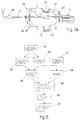
- the reference number 10 generally indicates a sandwich board for scaffolding or formworks obtained by the method according to the invention.
- the board 10 comprises an inner filling body 11 and an outer multi-layered reinforcement part 12 which covers at least the longitudinal faces.
- the inner filling body 11 is advantageously made in expanded polyurethane but other expanded material (balsa, particle boards, boards obtained from the recycling of urban refuse, honey comb boards or other) can also be used.
- the multi-layered outer covering part 12 may be made of glass fibres, carbon fibres, aramidic fibres, or similar fibres of vegetable, mineral or organic origin.
- the multi-layered outer covering part 12 is fed in continuous thread form, and/or continuous weave form, and/or continuous mat form.
- the multi-layered outer covering part 12 and/or the inner filling body 11 are impregnated with resin before they cooperate with the formation and polymerization mold 13 where the resin is polymerized.
- the resin may be advantageously of the type which hardens with heat, in which case the formation and polymerization mold 13 is advantageously heated.
- the board 10 is made of an inner filling body 11, a first inner reinforcement layer 12a made of glass fibre weave, a second intermediate reinforcement layer 12b made of a mat of glass fibre threads and a third outer protection layer 12c made of a veil of non-woven material.
- both the first inner reinforcement layer 12a and the third outer protection layer 12c have their edges superimposed.
- the third outer layer 12c substantially has the function of protecting the board from atmospheric agents and the light.
- the outer surface of the third outer layer is advantageously made of nonslip materail.
- pultrusion is carried out by means of a mold 13.
- the continuous material which constitutes the multi-layered outer reinforcement part 12 undergoes pultrusion while at the same time the inner filling body 11 is continuously inserted, in the form of a finished hard element, inside the continuous material which constitutes the outer reinforcement layer 12.
- the inner filling bodies 11 are produced in the mold upstream (phase 33; fig. 6), either directly in the finished dimensions (34), or sectioned from multiple-dimensioned blocks (35), and fed in axial alignment, continuously and with substantial continuity.
- the preparation phase of the inner filling body 11 is separate from the pultrusion line.
- the inner filling bodies (11) are arranged in their finished state, for example in a stack 23, and then fed sequentially and continuously to the mold 13 where the covering is carried out.
- the inner filling bodies 11 are arranged in the mold 31 on the same line as the formation and polymerization mold 13, and if necessary they undergo a superficial sanding (36), which is carried out in line in the appropriate station 32 and they are then sent in sequence and continuously to the covering station (38).
- a superficial sanding 36
- the sanding of their surfaces has the purpose of increasing the grip of the inner filling body 11 on the outer reinforcement layer 12.
- the continuous material which constitutes the multi-layered outer reinforcement part 12 is arranged (37) and then impregnated with part of the resin (39) which polymerizes inside the mold 13, and this causes a close contact and a reciprocal resistent attachment between the inner filling body 11 and the outer reinforcement layer 12.
- the impregnation with at least part of the resin takes place after the continuous material which constitutes the outer reinforcement layer 12 has come into contact with the inner filling bodies 11.
- At least part of the resin is applied directly onto the inner filling bodies 11.
- the plant 15 which carries out the method according to the invention comprises a feed unit 16 for the continuous material which constitutes the multi-layered outer reinforcement part 12, and a feed unit 17 for the inner filling bodies 11.
- impregnation station 18 with resin in this case comprising a bath 25 in which the multi-layered reinforcement part is immersed before being sent, together with the relative filling body 11, by means of the deflector means 22, into the formation and polymerization mold 13.
- the enclosed figures illustrate how impregnation with the resin takes place when the multi-layered reinforcement part 12, comprising three layers 12a, 12b, and 12c, previously put together, is already formed.
- each single layer 12a, 12b, and 12c is impregnated singly with resin and then sent inside the formation and polymerizatiion mold 13 where they are coupled with the inner filling body 11.
- a drawing unit 19 Downstream from the mold 13 is a drawing unit 19 which cooperates with a shearing unit 20 which shears (40) the continuous multi-layered part 12 and finishes the edges.
- the board thus obtained is then sent to a collection and stacking unit 21.
- the feed unit 17 for the inner filling bodies 11 is positioned in axis with the direction of feed of the continuous material which constitutes the outer reinforcement layer 12, which in this case passes both above and below the feed unit 17.
- the feed unit 17 has two feed stations, 17a and 17b, arranged on both sides of the direction of feed of the continuous material which constitutes the outer reinforcement layer 12.
- Each station 17a and 17b has a respective stack 23a and 23b to guarantee greater continuity to the plant 15 and to facilitate the operations of supplying the inner filling bodies 11.
- the plant 15 illustrated in Fig. 2 has a covering station 24 in line, with at least one wide longitudinal face of the board 10, with nonslip elements.
- the covering station 24 can, for example, carry out the surface abrasion of a wide longitudinal face of the board 10, the application of a layer of liquid resin by means of pouring or spraying, and the application of granular elements, such as sand, to make the surface rough.
- the plant 15 downstream of the transverse shearing unit 20, the plant 15 has a sealing unit, not illustrated here, to seal at least one end of the board 10, to prevent damage to the inner filling body 11.
- the plant 15 can have, in association with the sealing station, or downstream of it, a station where customizing (41) is carried out on the ends of the board 10.
- customizing station metallic box-type structures 28 may be applied with integral anchoring means 30, possibly by including attachment seatings.
- the anchoring means 30 are applied directly onto the board 10, for example by means of screws, by gluing, jointing, or by means of pressure under heat.
- Fig. 4 shows a customized board 10 with transverse through holes 26 into which cylinders 27 have been inserted, made of plastic or metal, with which the tie-rods can cooperate during assembly.
- Fig. 5 shows a customized board 10 with box-like elements at the end 28, carrying anchoring means 30, attached to the board 10 by means of a plurality of rivets 29.
Landscapes
- Engineering & Computer Science (AREA)
- Mechanical Engineering (AREA)
- Chemical & Material Sciences (AREA)
- Composite Materials (AREA)
- Architecture (AREA)
- Robotics (AREA)
- Civil Engineering (AREA)
- Structural Engineering (AREA)
- Moulding By Coating Moulds (AREA)
- Casting Or Compression Moulding Of Plastics Or The Like (AREA)
- Laminated Bodies (AREA)
Applications Claiming Priority (3)
| Application Number | Priority Date | Filing Date | Title |
|---|---|---|---|
| ITUD950140 | 1995-07-14 | ||
| IT95UD000140A IT1280200B1 (it) | 1995-07-14 | 1995-07-14 | Procedimento di produzione in continuo di tavole sandwich e relativo impianto |
| CA002203722A CA2203722A1 (fr) | 1995-07-14 | 1997-04-25 | Methode de fabrication continue de panneaux sandwich pour echaffaudages et coffrages, et panneaux sandwich pour echaffaudages et coffrages produits selon cette methode |
Publications (2)
| Publication Number | Publication Date |
|---|---|
| EP0753394A2 true EP0753394A2 (fr) | 1997-01-15 |
| EP0753394A3 EP0753394A3 (fr) | 1997-10-15 |
Family
ID=31496447
Family Applications (1)
| Application Number | Title | Priority Date | Filing Date |
|---|---|---|---|
| EP96111184A Withdrawn EP0753394A3 (fr) | 1995-07-14 | 1996-07-11 | Procédé pour la fabrication en continu de panneaux sandwich pour échafaudage et pour coffrage et produits par le procédé |
Country Status (3)
| Country | Link |
|---|---|
| EP (1) | EP0753394A3 (fr) |
| CA (1) | CA2203722A1 (fr) |
| IT (1) | IT1280200B1 (fr) |
Cited By (19)
| Publication number | Priority date | Publication date | Assignee | Title |
|---|---|---|---|---|
| WO2000068527A1 (fr) | 1999-05-08 | 2000-11-16 | Tannhaeuser Gunter | Panneau de montage rapide et de decoffrage et procede permettant de le dresser et procede et dispositif permettant de le produire |
| DE19921037A1 (de) * | 1999-05-08 | 2000-11-30 | Genima Innovations Marketing G | Schnellbau- und Schaltafel |
| WO2006092514A3 (fr) * | 2005-03-03 | 2007-03-29 | Coriolis Composites | Machine d'application de fibres |
| WO2010023342A2 (fr) * | 2008-08-26 | 2010-03-04 | Crisanto Palacios Gavilan | Panneau de coffrage |
| US7819160B2 (en) | 2007-02-28 | 2010-10-26 | Coriolis Composites | Device for using fibers with flexible fiber-routing tubes |
| US7926537B2 (en) | 2007-03-06 | 2011-04-19 | Coriolis Composites | Applicator head for fibers with particular systems for cutting fibers |
| US8052819B2 (en) | 2009-04-02 | 2011-11-08 | Coriolis Composites | Method and machine for applying a band of fibers on convex surfaces and/or with edges |
| US8057618B2 (en) | 2007-02-21 | 2011-11-15 | Coriolis Composites | Method and apparatus for making structures of composite material, in particular airplane fuselage sections |
| US8191596B2 (en) | 2009-07-17 | 2012-06-05 | Coriolis Composites | Fiber application machine comprising a flexible compacting roller with a thermal regulation system |
| CN103286991A (zh) * | 2013-05-24 | 2013-09-11 | 南京工业大学 | 一种拉挤成型的木质芯材复合材料夹层板及其生产工艺 |
| CN103589127A (zh) * | 2012-08-15 | 2014-02-19 | 上海杰事杰新材料(集团)股份有限公司 | 一种高横向强度拉挤结构板材及其制作方法 |
| DE102015203313A1 (de) * | 2015-02-24 | 2016-08-25 | Bayerische Motoren Werke Aktiengesellschaft | Pultrusionsverfahren zur Herstellung von faserverstärkten Kunststoffprofilen |
| DE102015203315A1 (de) * | 2015-02-24 | 2016-08-25 | Bayerische Motoren Werke Aktiengesellschaft | Pultrusionsverfahren zur Herstellung von faserverstärkten Kunststoffprofilen |
| EP3124219A1 (fr) * | 2015-07-30 | 2017-02-01 | General Electric Company | Traitement en ligne de produits pultrudés préformés destinés à être utilisés à l'intérieur d'une pale de rotor de turbine éolienne |
| US10369594B2 (en) | 2015-04-01 | 2019-08-06 | Coriolis Group | Fiber application head with a specific application roll |
| CN111391365A (zh) * | 2020-03-27 | 2020-07-10 | 苏州市永盛防火材料有限公司 | 一种玻璃钢夹芯板拉挤成型工艺 |
| US10821682B2 (en) | 2015-10-28 | 2020-11-03 | Coriolis Group | Fiber application machine comprising specific cutting systems |
| US10894341B2 (en) | 2016-03-07 | 2021-01-19 | Coriolis Group | Method for producing preforms with application of a binder to dry fiber, and corresponding machine |
| US11491741B2 (en) | 2016-09-27 | 2022-11-08 | Coriolis Group | Process for producing composite material parts by impregnating a specific preform |
Families Citing this family (2)
| Publication number | Priority date | Publication date | Assignee | Title |
|---|---|---|---|---|
| US20160009046A1 (en) * | 2012-11-13 | 2016-01-14 | Consystex Pty Ltd | Formwork or construction element and a new material |
| CN115059289A (zh) * | 2022-06-24 | 2022-09-16 | 武汉鸿立盛建筑工程安装有限责任公司 | 一种热塑性复合材料建筑模壳及成型方法 |
Citations (9)
| Publication number | Priority date | Publication date | Assignee | Title |
|---|---|---|---|---|
| GB963150A (en) * | 1959-10-15 | 1964-07-08 | Boelkow Ludwig | Improvements relating to flexible bar-shaped elements |
| US3367821A (en) * | 1964-10-19 | 1968-02-06 | Universal Moulded Fiber Glass | Method of applying a fiber reinforced resin layer to each side of a temporarily assembled pair of panels |
| US4028477A (en) * | 1971-12-16 | 1977-06-07 | Shell Oil Company | Method of producing an article of thermosetting resin |
| US4078348A (en) * | 1976-10-18 | 1978-03-14 | Michael Rothman | Construction panels for structural support systems |
| EP0108576A2 (fr) * | 1982-11-05 | 1984-05-16 | G. Maunsell & Partners | Eléments de sol ou de toit supportants |
| GB2144683A (en) * | 1983-06-16 | 1985-03-13 | Ramage Lanes Morton | A fibre reinforced beam |
| EP0158118A2 (fr) * | 1984-04-11 | 1985-10-16 | Grillo-Werke Aktiengesellschaft | Procédé et appareil pour la fabrication de profilés en matière composite |
| US4681722A (en) * | 1985-10-07 | 1987-07-21 | Owens-Corning Fiberglas Corporation | Method of making a lineal structural member |
| JPH04339635A (ja) * | 1991-02-08 | 1992-11-26 | Sekisui Chem Co Ltd | 繊維強化合成樹脂複合体及びその成形方法 |
-
1995
- 1995-07-14 IT IT95UD000140A patent/IT1280200B1/it active IP Right Grant
-
1996
- 1996-07-11 EP EP96111184A patent/EP0753394A3/fr not_active Withdrawn
-
1997
- 1997-04-25 CA CA002203722A patent/CA2203722A1/fr not_active Abandoned
Patent Citations (9)
| Publication number | Priority date | Publication date | Assignee | Title |
|---|---|---|---|---|
| GB963150A (en) * | 1959-10-15 | 1964-07-08 | Boelkow Ludwig | Improvements relating to flexible bar-shaped elements |
| US3367821A (en) * | 1964-10-19 | 1968-02-06 | Universal Moulded Fiber Glass | Method of applying a fiber reinforced resin layer to each side of a temporarily assembled pair of panels |
| US4028477A (en) * | 1971-12-16 | 1977-06-07 | Shell Oil Company | Method of producing an article of thermosetting resin |
| US4078348A (en) * | 1976-10-18 | 1978-03-14 | Michael Rothman | Construction panels for structural support systems |
| EP0108576A2 (fr) * | 1982-11-05 | 1984-05-16 | G. Maunsell & Partners | Eléments de sol ou de toit supportants |
| GB2144683A (en) * | 1983-06-16 | 1985-03-13 | Ramage Lanes Morton | A fibre reinforced beam |
| EP0158118A2 (fr) * | 1984-04-11 | 1985-10-16 | Grillo-Werke Aktiengesellschaft | Procédé et appareil pour la fabrication de profilés en matière composite |
| US4681722A (en) * | 1985-10-07 | 1987-07-21 | Owens-Corning Fiberglas Corporation | Method of making a lineal structural member |
| JPH04339635A (ja) * | 1991-02-08 | 1992-11-26 | Sekisui Chem Co Ltd | 繊維強化合成樹脂複合体及びその成形方法 |
Non-Patent Citations (1)
| Title |
|---|
| PATENT ABSTRACTS OF JAPAN vol. 017, no. 191 (M-1396), 14 April 1993 & JP 04 339635 A (SEKISUI CHEM CO LTD), 26 November 1992, * |
Cited By (24)
| Publication number | Priority date | Publication date | Assignee | Title |
|---|---|---|---|---|
| WO2000068527A1 (fr) | 1999-05-08 | 2000-11-16 | Tannhaeuser Gunter | Panneau de montage rapide et de decoffrage et procede permettant de le dresser et procede et dispositif permettant de le produire |
| DE19921037A1 (de) * | 1999-05-08 | 2000-11-30 | Genima Innovations Marketing G | Schnellbau- und Schaltafel |
| DE19921037C2 (de) * | 1999-05-08 | 2001-09-27 | Genima Innovations Marketing G | Schnellbau- und Schaltafel sowie Verfahren zum Zurichten einer solchen |
| WO2006092514A3 (fr) * | 2005-03-03 | 2007-03-29 | Coriolis Composites | Machine d'application de fibres |
| US8733417B2 (en) | 2005-03-03 | 2014-05-27 | Coriolis Composites | Fiber application machine |
| US8057618B2 (en) | 2007-02-21 | 2011-11-15 | Coriolis Composites | Method and apparatus for making structures of composite material, in particular airplane fuselage sections |
| US7819160B2 (en) | 2007-02-28 | 2010-10-26 | Coriolis Composites | Device for using fibers with flexible fiber-routing tubes |
| US7926537B2 (en) | 2007-03-06 | 2011-04-19 | Coriolis Composites | Applicator head for fibers with particular systems for cutting fibers |
| WO2010023342A2 (fr) * | 2008-08-26 | 2010-03-04 | Crisanto Palacios Gavilan | Panneau de coffrage |
| WO2010023342A3 (fr) * | 2008-08-26 | 2010-05-14 | Crisanto Palacios Gavilan | Panneau de coffrage |
| US8052819B2 (en) | 2009-04-02 | 2011-11-08 | Coriolis Composites | Method and machine for applying a band of fibers on convex surfaces and/or with edges |
| US8191596B2 (en) | 2009-07-17 | 2012-06-05 | Coriolis Composites | Fiber application machine comprising a flexible compacting roller with a thermal regulation system |
| CN103589127A (zh) * | 2012-08-15 | 2014-02-19 | 上海杰事杰新材料(集团)股份有限公司 | 一种高横向强度拉挤结构板材及其制作方法 |
| CN103589127B (zh) * | 2012-08-15 | 2016-12-21 | 上海杰事杰新材料(集团)股份有限公司 | 一种高横向强度拉挤结构板材及其制作方法 |
| CN103286991A (zh) * | 2013-05-24 | 2013-09-11 | 南京工业大学 | 一种拉挤成型的木质芯材复合材料夹层板及其生产工艺 |
| CN103286991B (zh) * | 2013-05-24 | 2015-11-11 | 南京工业大学 | 一种拉挤成型的木质芯材复合材料夹层板及其生产工艺 |
| DE102015203313A1 (de) * | 2015-02-24 | 2016-08-25 | Bayerische Motoren Werke Aktiengesellschaft | Pultrusionsverfahren zur Herstellung von faserverstärkten Kunststoffprofilen |
| DE102015203315A1 (de) * | 2015-02-24 | 2016-08-25 | Bayerische Motoren Werke Aktiengesellschaft | Pultrusionsverfahren zur Herstellung von faserverstärkten Kunststoffprofilen |
| US10369594B2 (en) | 2015-04-01 | 2019-08-06 | Coriolis Group | Fiber application head with a specific application roll |
| EP3124219A1 (fr) * | 2015-07-30 | 2017-02-01 | General Electric Company | Traitement en ligne de produits pultrudés préformés destinés à être utilisés à l'intérieur d'une pale de rotor de turbine éolienne |
| US10821682B2 (en) | 2015-10-28 | 2020-11-03 | Coriolis Group | Fiber application machine comprising specific cutting systems |
| US10894341B2 (en) | 2016-03-07 | 2021-01-19 | Coriolis Group | Method for producing preforms with application of a binder to dry fiber, and corresponding machine |
| US11491741B2 (en) | 2016-09-27 | 2022-11-08 | Coriolis Group | Process for producing composite material parts by impregnating a specific preform |
| CN111391365A (zh) * | 2020-03-27 | 2020-07-10 | 苏州市永盛防火材料有限公司 | 一种玻璃钢夹芯板拉挤成型工艺 |
Also Published As
| Publication number | Publication date |
|---|---|
| EP0753394A3 (fr) | 1997-10-15 |
| IT1280200B1 (it) | 1998-01-05 |
| ITUD950140A1 (it) | 1997-01-14 |
| CA2203722A1 (fr) | 1998-10-25 |
| ITUD950140A0 (it) | 1995-07-14 |
Similar Documents
| Publication | Publication Date | Title |
|---|---|---|
| EP0753394A2 (fr) | Procédé pour la fabrication en continu de panneaux sandwich pour échafaudage et pour coffrage et produits par le procédé | |
| CN1127403C (zh) | 具有树脂分配网路的大型复合结构的制造方法 | |
| US5230844A (en) | Process for producing a complex elastic molded structure of the sandwich type | |
| US4250136A (en) | Method of forming a composite structure | |
| US4091142A (en) | Structural panel and method of making same | |
| KR920003059B1 (ko) | 섬유강화 플라스틱 구조물 및 그 제조방법 | |
| US4353947A (en) | Laminated composite structure and method of manufacture | |
| CA2673013C (fr) | Ames et panneaux composites renforces par fibres | |
| US3915783A (en) | Making a thermosetting resin impregnating laminate | |
| US4028477A (en) | Method of producing an article of thermosetting resin | |
| NL9200963A (nl) | Werkwijze voor het vervaardigen van een grootschalig voorwerp van met vezels versterkte synthetische hars, alsmede een kern voor gebruik bij deze werkwijze. | |
| EP0831988A1 (fr) | Procede permettant la realisation d'une extrusion par etirage par injection de resine en utilisant plusieurs resines | |
| JPS5850600B2 (ja) | 未硬化樹脂を含浸した連続的長さの層状シ−ト構造体を形成する装置 | |
| JP2007526375A (ja) | 熱可塑性pbtプラスチック材料を形成するための環状オリゴマーの加工 | |
| WO1982003789A1 (fr) | Procede de fabrication d'un baton et baton fabrique selon ce procede | |
| WO1998038031A3 (fr) | Perfectionnements de procedes de moulage et de pieces moulees | |
| WO2003078735A1 (fr) | Traverses composites a conduit integre facultatif | |
| US4510105A (en) | Method of manufacturing a surface-reinforced foam article | |
| EP1718454B1 (fr) | Procede de resine sous vide mettant en oeuvre une couche de drainage et destine a des blocs de marbre | |
| US4028460A (en) | Method for making fiber reinforced resin grating | |
| CA1114729A (fr) | Methode de fabrication d'articles en plastique armes de forte epaisseur | |
| US3704561A (en) | Fiber reinforced resin grating | |
| US3328818A (en) | Reinforced walk ramp | |
| DE1813980A1 (de) | Mehrschichtplatte | |
| US3367821A (en) | Method of applying a fiber reinforced resin layer to each side of a temporarily assembled pair of panels |
Legal Events
| Date | Code | Title | Description |
|---|---|---|---|
| PUAI | Public reference made under article 153(3) epc to a published international application that has entered the european phase |
Free format text: ORIGINAL CODE: 0009012 |
|
| AK | Designated contracting states |
Kind code of ref document: A2 Designated state(s): DE ES FR IT |
|
| PUAL | Search report despatched |
Free format text: ORIGINAL CODE: 0009013 |
|
| AK | Designated contracting states |
Kind code of ref document: A3 Designated state(s): DE ES FR IT |
|
| 17P | Request for examination filed |
Effective date: 19980217 |
|
| 17Q | First examination report despatched |
Effective date: 19990726 |
|
| STAA | Information on the status of an ep patent application or granted ep patent |
Free format text: STATUS: THE APPLICATION IS DEEMED TO BE WITHDRAWN |
|
| 18D | Application deemed to be withdrawn |
Effective date: 19991207 |