EP0753366B1 - Spanabhebendes Schneidwerkzeug - Google Patents
Spanabhebendes Schneidwerkzeug Download PDFInfo
- Publication number
- EP0753366B1 EP0753366B1 EP96110110A EP96110110A EP0753366B1 EP 0753366 B1 EP0753366 B1 EP 0753366B1 EP 96110110 A EP96110110 A EP 96110110A EP 96110110 A EP96110110 A EP 96110110A EP 0753366 B1 EP0753366 B1 EP 0753366B1
- Authority
- EP
- European Patent Office
- Prior art keywords
- gripping
- plate
- trough
- clamping
- claw
- Prior art date
- Legal status (The legal status is an assumption and is not a legal conclusion. Google has not performed a legal analysis and makes no representation as to the accuracy of the status listed.)
- Revoked
Links
Images



Classifications
-
- B—PERFORMING OPERATIONS; TRANSPORTING
- B23—MACHINE TOOLS; METAL-WORKING NOT OTHERWISE PROVIDED FOR
- B23B—TURNING; BORING
- B23B27/00—Tools for turning or boring machines; Tools of a similar kind in general; Accessories therefor
- B23B27/14—Cutting tools of which the bits or tips or cutting inserts are of special material
- B23B27/16—Cutting tools of which the bits or tips or cutting inserts are of special material with exchangeable cutting bits or cutting inserts, e.g. able to be clamped
- B23B27/1677—Cutting tools of which the bits or tips or cutting inserts are of special material with exchangeable cutting bits or cutting inserts, e.g. able to be clamped with plate-like cutting inserts clamped by a clamping member acting almost perpendicularly on the chip-forming plane and at the same time upon the wall of a hole in the insert
-
- Y—GENERAL TAGGING OF NEW TECHNOLOGICAL DEVELOPMENTS; GENERAL TAGGING OF CROSS-SECTIONAL TECHNOLOGIES SPANNING OVER SEVERAL SECTIONS OF THE IPC; TECHNICAL SUBJECTS COVERED BY FORMER USPC CROSS-REFERENCE ART COLLECTIONS [XRACs] AND DIGESTS
- Y10—TECHNICAL SUBJECTS COVERED BY FORMER USPC
- Y10T—TECHNICAL SUBJECTS COVERED BY FORMER US CLASSIFICATION
- Y10T407/00—Cutters, for shaping
- Y10T407/22—Cutters, for shaping including holder having seat for inserted tool
- Y10T407/2272—Cutters, for shaping including holder having seat for inserted tool with separate means to fasten tool to holder
-
- Y—GENERAL TAGGING OF NEW TECHNOLOGICAL DEVELOPMENTS; GENERAL TAGGING OF CROSS-SECTIONAL TECHNOLOGIES SPANNING OVER SEVERAL SECTIONS OF THE IPC; TECHNICAL SUBJECTS COVERED BY FORMER USPC CROSS-REFERENCE ART COLLECTIONS [XRACs] AND DIGESTS
- Y10—TECHNICAL SUBJECTS COVERED BY FORMER USPC
- Y10T—TECHNICAL SUBJECTS COVERED BY FORMER US CLASSIFICATION
- Y10T407/00—Cutters, for shaping
- Y10T407/22—Cutters, for shaping including holder having seat for inserted tool
- Y10T407/2272—Cutters, for shaping including holder having seat for inserted tool with separate means to fasten tool to holder
- Y10T407/2274—Apertured tool
- Y10T407/2276—Apertured tool with means projecting through aperture to force tool laterally against reaction surface
-
- Y—GENERAL TAGGING OF NEW TECHNOLOGICAL DEVELOPMENTS; GENERAL TAGGING OF CROSS-SECTIONAL TECHNOLOGIES SPANNING OVER SEVERAL SECTIONS OF THE IPC; TECHNICAL SUBJECTS COVERED BY FORMER USPC CROSS-REFERENCE ART COLLECTIONS [XRACs] AND DIGESTS
- Y10—TECHNICAL SUBJECTS COVERED BY FORMER USPC
- Y10T—TECHNICAL SUBJECTS COVERED BY FORMER US CLASSIFICATION
- Y10T407/00—Cutters, for shaping
- Y10T407/24—Cutters, for shaping with chip breaker, guide or deflector
Definitions
- the invention relates to a cutting tool according to the preamble of claim 1.
- EP-A1-0 075 177 describes a generic cutting tool with a clamp holder known, which has a recess for receiving a ceramic cutting plate.
- the cutting plate is provided with a clamping trough into which an attachment is provided Claw grips.
- the clamping claw is on the via a clamping screw Clamp holder attached.
- the attachment of the clamping claw touches the clamping trough at points, the contact is such that a force component Pulling the insert into the recess. This is achieved in that the point of contact between the trough bottom and the insert surface.
- Clamping system also a clamping system for inserts without a clamping trough shown.
- the same clamp holder is used as described above.
- the clamping system differs in that it has a pressure plate attached to the clamping claw is attached. This pressure plate presses with a flat surface Insert on the clamp holder and only has the task of pressing vertically to ensure the cutting plate so that the cutting plate does not come out of the clamp holder slips.
- a cutting tool is known in which a clamping claw is held in the clamp so that it is in the direction of the clamping screw by an additional clamping component that is between the screw head and Clamping claw is arranged, is subjected to force.
- the clamp grips directly into a hole in the insert with an extension.
- the disadvantage is that the workpiece on next lying area of the nose of the clamping claw by the impact of the chips is washed out, i.e. there is a material removal, which in the clamping trough engaging approach of the clamping claw can break in extreme cases.
- the clamping claw also builds very high, making it difficult to remove chips becomes.
- there is particularly in the case of long-chipping materials Danger of a chip in the gap at the point of contact of the approach Clamping claw clamped with the clamping trough. This leads to a build-up of chips, that can damage the workpiece surface or break the clamping claw leads.
- the invention has for its object a cutting tool according to the preamble of claim 1 to improve such that the front facing the workpiece the clamping claw is largely protected from the chips and thereby an optimal one Fit of the insert in the clamp holder is guaranteed.
- this object is achieved in that a Clamping plate is attached, which rests on the cutting plate, that the clamping claw Clamping plate pulls in the direction of the clamping screw on the one facing the cutting plate Underside of the clamping plate is provided with a cam that is with the clamping trough or the hole is in exciting contact and that of the clamping claw Upstream top of the clamping plate higher than the one below the clamping claw Surface of the clamping plate is so that the front part of the clamping claw in front impacting chips is protected.
- the height of the cam on the clamping plate is chosen according to the invention so that it is between the distance between the trough bottom Hollow top is.
- the insert is always removed from the clamping plate or the clamping claw is pulled into the insert seat.
- the clamping plate has an inclined plane or notch on the top, in which engages the approach of the clamp so that a force component in the direction Clamping screw is generated.
- the clamping plate and thus the cutting plate are thus subjected to force in the direction of the clamping screw.
- the cam on the clamping plate touches the trough in the area of the inclined or curved transition surface, which extends from the trough bottom to the top of the trough.
- the cam of the clamping plate contacts the clamping trough or the hole punctiform, linear or flat.
- the cam at the point of contact with the clamping trough or the bore cylindrical, barrel or spherical shape.
- the trough must of course be adapted to it.
- the width of the cam of the clamping plate is smaller than the width of the clamping trough or bore so that the cam in the clamping trough or the bore can intervene.
- the clamping trough or the bore at least almost completely from. According to the invention, this improves the removal of the chips Outer contour of the clamping plate facing the workpiece with bevels in the the upper side of the clamping plate in front of the clamping claw.
- the Clamping claw in front of the upper side of the clamping plate higher than that below the Clamping claw arranged surface of the clamping plate, so that the front part of the Clamping claw is protected from impacting chips.
- Fig. 1 shows a section of a cutting tool with a clamp holder 1, in which a recess 2 for receiving a cutting plate 3 is arranged is.
- a clamping trough 4 On the top of the cutting plate 3 is a clamping trough 4 provided, in which a cam 9 of a clamping plate 5 engages.
- the clamping plate 5 is in turn attached to a clamping claw 6, which rotatably via a Clamping screw 7 is fixed in the clamp holder 1.
- the clamping plate 5 has on her Top side of a longitudinal and a transverse groove. A web engages in the longitudinal groove Clamping claw 6.
- an attachment 15 is in the claw 6 Arranged transversely.
- This approach 15 engages in the transverse groove or notch 14 in the clamping plate 5 so that a force component in the direction of Tension screw 7 results (see Fig. 2 to 6).
- the clamping plate 5 is thus through the approach 15 in connection with the notch 14 always in the direction of the clamping screw 7 pulled.
- Recess 16 There is one on each of the two long sides of the clamping plate 5 Recess 16 arranged in which a spring element 17 in the form of a U-leg intervenes. By this spring element 17, the clamping plate 5 is after pressed onto the clamp 6 at the top.
- a cam 9 is arranged on the underside, i.e. on the cutting plate 3 facing side of the clamping plate 5.
- the amount of this Cam 9 is selected so that it is between the distance between the trough bottom 10 Trough top 11 is located (see Figures 3 and 4), one exciting touch occurs.
- the cam on the clamping plate touches the Trough in the area of the inclined or curved transition surface extends from the trough bottom to the top of the trough.
- the underside of the clamping plate 5 lies fully on the top side of the insert on and completely covers the clamping trough 4.
- the touch of the cam 9 of the Clamping plate 5 with the clamping trough 4 can be punctiform, linear or be flat. With a punctiform touch the best Results achieved.
- the cam 9 can for this purpose at its point of contact be cylindrical, barrel-shaped or spherical. This must be adjusted of course, the clamping trough 4 may be formed.
- the width of the cam 9 is of course smaller than the width of the clamping trough 4, so that the cam 9 in the trough 4 can intervene.
- the one facing the workpiece, not shown Outer contour of the clamping plate 5 is provided with bevels 12 which in the Clamping claw 6 pass over the upper side of the clamping plate 5.
- bevels 12 which in the Clamping claw 6 pass over the upper side of the clamping plate 5.
- the clamping claw 6 Top of the clamping plate 5 higher than that below the clamping claw 6 arranged surface of the clamping plate 5.
- the upstream of the clamping claw 6 The top of the clamping plate 5 thus forms a kind of protective shield.
- Fig. 2 shows a plan view of a prismatic cutting plate 3, the Clamping recess 4 is covered by a clamping plate 5 with cams. Good to can be seen the bevels 12 on the front of the clamping plate 5. Die The embodiment shown here is identical to that shown in FIG. 1.
- Figures 3 and 4 each show a cross section through the Cutting tool, as in Fig. 1, but on an enlarged scale.
- 4 is a Section along the section line IV - IV of Fig. 2 and in Fig. 3 is an enlarged 1 in accordance with the circle marked III.
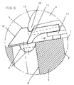
- Fig. 5 shows in cross section a clamping plate 5 with a cylindrical or hemispherical cam 9 which in a cylindrical bore 8 a Cutting plate 3 engages.
- the design of the cylindrical cam 9 is shown in dashed lines.
- the height of the cam 9 is in this embodiment of minor importance. However, there must be an exciting touch can be achieved. Otherwise, this embodiment is the same as previously shown identical.
- Fig. 6 shows an embodiment comparable to Fig. 5, only here the hemispherical cams 9 in an upper region of the bore 8 attached conical bore or extension 19. Otherwise, too this embodiment is identical to that previously shown.
- the bore or Extension 19 can also be conveniently conical, spherical or the like.
Landscapes
- Engineering & Computer Science (AREA)
- Mechanical Engineering (AREA)
- Cutting Tools, Boring Holders, And Turrets (AREA)
- Jigs For Machine Tools (AREA)
Description
- Fig. 1
- einen Ausschnitt aus einem Schneidwerkzeug mit eingelegter Schneidplatte, die über eine Spannpratze und Spannplatte im Plattensitz befestigt ist,
- Fig. 2
- eine Draufsicht auf eine prismatische Schneidplatte, deren Spannmulde von einer Spannplatte mit Nocken abgedeckt wird,
- Fig. 3
- einen vergrößerten Ausschnitt aus Fig. 1 gemäß dem mit III gekennzeichneten Kreis,
- Fig. 4
- einen Schnitt durch die Spannplatte mit Nocken und Schneidplatte gemäß der Schnittlinie IV - IV aus Fig. 2,
- Fig. 5
- eine Spannplatte mit zylindrischem oder halbkugelförmigem Nocken, der in die zylindrische Bohrung einer Schneidplatte eingreift und
- Fig. 6
- eine Spannplatte mit halbkugelförmigem Nocken, der in eine kegelförmige Bohrung einer Schneidplatte eingreift.
Claims (8)
- Spanabhebendes Schneidwerkzeug, insbesondere Drehmeißel, im wesentlichen bestehend aus einem Klemmhalter (1), der eine Ausnehmung (2) zur Aufnahme einer Schneidplatte (3) aufweist, wobei die Schneidplatte (3) mit einer Spannmulde (4) oder einer Bohrung (8) versehen ist, die von einer Spannpratze (6) im Klemmhalter (1) gehalten ist und die Spannpratze (6) über eine Spannschraube (7) auf dem Klemmhalter (1) festliegt, dadurch gekennzeichnet,daß an der Spannpratze (6) eine Spannplatte (5) befestigt ist, die auf der Schneidplatte (3) aufliegt,daß die Spannpratze (6) die Spannplatte (5) in Richtung Spannschraube (7) zieht,daß auf der zur Schneidplatte (3) gewandten Unterseite die Spannplatte (5) mit einem Nocken (9) versehen ist, der mit der Spannmulde (4) bzw. der Bohrung (8) in spannender Berührung steht unddaß die der Spannpratze (6) vorgelagerte Oberseite der Spannplatte (5) höher als die unterhalb der Spannpratze (6) angeordnete Oberfläche der Spannplatte (5) ist, so daß das Vorderteil (13) der Spannpratze (6) vor aufprallenden Spänen geschützt ist.
- Schneidwerkzeug nach Anspruch 1, dadurch gekennzeichnet, daß die Höhe des Nockens (9) an der Spannplatte (5) zwischen dem Abstand Muldenboden (10) zu Muldenoberseite (11) liegt.
- Schneidwerkzeug nach einem der Ansprüche 1 oder 2, dadurch gekennzeichnet, daß die Berührung des Nockens (9) der Spannplatte (5) mit der Spannmulde (4) bzw. der Bohrung (8) punktförmig, linienförmig oder flächenförmig erfolgt.
- Schneidwerkzeug nach einem der Ansprüche 1 bis 3, dadurch gekennzeichnet, daß der Nocken (9) der Spannplatte (5) im Berührungspunkt mit der Spannmulde (4) bzw. der Bohrung (8) zylindrisch, tonnen- oder kugelförmig geformt ist.
- Schneidwerkzeug nach einem der Ansprüche 1 bis 4, dadurch gekennzeichnet, daß die Breite des Nockens (9) der Spannplatte (5) kleiner als die Breite der Spannmulde (4) bzw. die Bohrung (8) ist.
- Schneidwerkzeug nach einem der Ansprüche 1 bis 5, dadurch gekennzeichnet, daß die Spannplatte (5) die Spannmulde (4) bzw. die Bohrung (8) mindestens nahezu vollständig abdeckt.
- Schneidwerkzeug nach einem der Ansprüche 1 bis 6, dadurch gekennzeichnet, daß die dem Werkstück zugewandte Außenkontur der Spannplatte (5) mit Abschrägungen (12) in die der Spannpratze (6) vorgelagerte Oberseite der Spannplatte (5) übergeht.
- Schneidwerkzeug nach einem der Ansprüche 1 bis 7, dadurch gekennzeichnet, daß die Spannplatte (5) auf der Oberseite eine schräge Ebene oder eine Kerbe (14) aufweist, in die ein Ansatz (15) der Spannpratze (6) so eingreift, daß eine Kraftkomponente in Richtung Spannschraube (7) erzeugt ist.
Applications Claiming Priority (2)
| Application Number | Priority Date | Filing Date | Title |
|---|---|---|---|
| DE19524945A DE19524945A1 (de) | 1995-07-08 | 1995-07-08 | Spanabhebendes Schneidwerkzeug |
| DE19524945 | 1995-07-08 |
Publications (2)
| Publication Number | Publication Date |
|---|---|
| EP0753366A1 EP0753366A1 (de) | 1997-01-15 |
| EP0753366B1 true EP0753366B1 (de) | 1998-08-19 |
Family
ID=7766359
Family Applications (1)
| Application Number | Title | Priority Date | Filing Date |
|---|---|---|---|
| EP96110110A Revoked EP0753366B1 (de) | 1995-07-08 | 1996-06-22 | Spanabhebendes Schneidwerkzeug |
Country Status (4)
| Country | Link |
|---|---|
| US (1) | US5820311A (de) |
| EP (1) | EP0753366B1 (de) |
| DE (2) | DE19524945A1 (de) |
| ES (1) | ES2119533T3 (de) |
Cited By (1)
| Publication number | Priority date | Publication date | Assignee | Title |
|---|---|---|---|---|
| CN101422821B (zh) * | 2001-07-26 | 2012-12-12 | 陶瓷技术有限责任公司 | 具有夹紧槽的刀片和该刀片在切削刀具中的应用 |
Families Citing this family (30)
| Publication number | Priority date | Publication date | Assignee | Title |
|---|---|---|---|---|
| SE512860C2 (sv) * | 1997-12-03 | 2000-05-22 | Sandvik Ab | Keramikskär |
| US6092447A (en) * | 1999-01-15 | 2000-07-25 | Screw Machine Tool Company, Inc. | Shave tool holder including a precise calibration assembly for machining a rotating workpiece |
| WO2000064615A1 (en) * | 1999-04-26 | 2000-11-02 | Sandvik Aktiebolag | A tool holder and a clamp plate for holding a cutting insert |
| US6379087B1 (en) * | 2000-02-07 | 2002-04-30 | Kennametal Inc. | Cutting insert with split face clamping surfaces and toolholder therefor |
| US6457914B1 (en) | 2000-08-24 | 2002-10-01 | Kennametal Inc. | Clamping tool holder |
| SE520629C2 (sv) * | 2000-09-05 | 2003-08-05 | Sandvik Ab | Skär för grovsvarvningsändamål med avsmalnande bakre ände |
| US6712564B1 (en) | 2000-09-29 | 2004-03-30 | Greenleaf Technology Corporation | Tool with improved resistance to displacement |
| DE10208266A1 (de) | 2001-07-26 | 2003-02-13 | Ceram Tec Ag Innovative Cerami | Spanabhebendes Schneidwerkzeug und Schneidplatte in Donut-Form |
| US7073986B2 (en) * | 2001-11-08 | 2006-07-11 | Kennametal Inc. | Dimpled insert with retaining clamp |
| EP1595648A3 (de) * | 2004-05-13 | 2009-05-27 | CeramTec AG | Zweigeteilte Spannpratze |
| JP2010520067A (ja) * | 2007-02-28 | 2010-06-10 | エレメント シックス (プロダクション)(プロプライエタリィ) リミテッド | 工作物の機械加工方法 |
| UA98637C2 (ru) * | 2007-02-28 | 2012-06-11 | Элемент Сикс (Продакшн) (Пти) Лтд | Деталь режущего инструмента |
| US7547163B2 (en) * | 2007-07-16 | 2009-06-16 | Kennametal Inc. | Clamping tool holder |
| US7510352B2 (en) * | 2007-08-03 | 2009-03-31 | Kennametal Inc. | Integral cutting insert clamping mechanism |
| US8491230B2 (en) * | 2007-08-10 | 2013-07-23 | Taegutec, Ltd. | Clamping device for a cutting insert |
| US8057131B2 (en) * | 2009-01-17 | 2011-11-15 | Kennametal Inc. | Clamping tool holder |
| WO2010104227A1 (en) * | 2009-03-13 | 2010-09-16 | Taegutec Ltd. | Tool holder clamp assembly for cutting inserts and its pressing plate |
| GB0908375D0 (en) | 2009-05-15 | 2009-06-24 | Element Six Ltd | A super-hard cutter element |
| JP5278758B2 (ja) * | 2009-05-15 | 2013-09-04 | 本田技研工業株式会社 | カム駆動装置及び加工方法 |
| DE102011080412A1 (de) | 2010-08-04 | 2012-02-09 | Ceramtec Gmbh | Schneidwerkzeug und Schneidplatte |
| IL211326A (en) * | 2011-02-21 | 2014-07-31 | Iscar Ltd | Cutting tools and cutting tool for him |
| JP2014147977A (ja) * | 2011-05-23 | 2014-08-21 | Tungaloy Corp | 切削インサートおよびその切削インサートを用いた切削工具 |
| KR101990608B1 (ko) * | 2011-10-06 | 2019-06-18 | 세람테크 게엠베하 | 소형화 절단 판 |
| US9511421B2 (en) * | 2013-06-14 | 2016-12-06 | Kennametal Inc. | Cutting tool assembly having clamp assembly comprising a clamp and a coolant plate |
| US20160016233A1 (en) * | 2014-07-17 | 2016-01-21 | Kennametal India Limited | Notched cutting inserts and applications thereof |
| DE102015224276A1 (de) * | 2014-12-05 | 2016-06-09 | Ceramtec Gmbh | Schneidplattengeometrie zur Schnittkraftreduzierung beim Stechdrehen und ziehenden Schnitt |
| RS62973B1 (sr) * | 2015-01-09 | 2022-03-31 | Ceram Gmbh | Noseći alat |
| HUE051280T2 (hu) * | 2017-03-22 | 2021-03-01 | Ceram Gmbh | Szerszámrendszer |
| US11969802B2 (en) | 2018-06-18 | 2024-04-30 | Filip JAMBRES | Cutting tool |
| PL248317B1 (pl) | 2022-12-30 | 2025-11-24 | Univ Morski W Gdyni | Zestaw do mocowania wieloostrzowego narzędzia do obróbki wykańczającej powierzchni pospawalniczych i sposób wytwarzania zestawu do mocowania wieloostrzowego narzędzia do obróbki wykańczającej powierzchni pospawalniczych |
Family Cites Families (14)
| Publication number | Priority date | Publication date | Assignee | Title |
|---|---|---|---|---|
| US2870523A (en) * | 1956-08-10 | 1959-01-27 | Theophile J La Lime | Cutting tools |
| US3303553A (en) * | 1964-08-24 | 1967-02-14 | Viking Tool Company | Cutting tool assembly |
| CA952701A (en) * | 1972-08-30 | 1974-08-13 | General Electric Company | Cutting tool |
| FR2210123A6 (de) * | 1972-12-11 | 1974-07-05 | Carmona Jean | |
| JPS5347131B2 (de) | 1973-02-07 | 1978-12-19 | ||
| JPS5015008A (de) * | 1973-06-15 | 1975-02-17 | ||
| US4078868A (en) * | 1977-04-06 | 1978-03-14 | The Ingersoll Milling Machine Company | Cutter having inserts clamped with wedges |
| US4189264A (en) * | 1978-09-15 | 1980-02-19 | Fansteel Inc. | Cutting insert and chip control assembly |
| DE3136549A1 (de) * | 1981-09-15 | 1983-03-31 | Feldmühle AG, 4000 Düsseldorf | Schneidwerkzeug |
| SU1250398A1 (ru) * | 1985-03-15 | 1986-08-15 | Ульяновский политехнический институт | Сборный резец |
| DE3740814A1 (de) * | 1987-12-02 | 1989-06-15 | Hertel Ag Werkzeuge Hartstoff | Klemmwerkzeug zur spanenden formgebung |
| US4938639A (en) * | 1989-05-12 | 1990-07-03 | Kennametal Inc. | Combination tool holder |
| JP2701514B2 (ja) * | 1989-06-15 | 1998-01-21 | 三菱マテリアル株式会社 | スローアウエイチップのクランプ機構 |
| US5501256A (en) * | 1994-07-18 | 1996-03-26 | U.S. Natural Resources, Inc. | Chipper knife |
-
1995
- 1995-07-08 DE DE19524945A patent/DE19524945A1/de not_active Withdrawn
-
1996
- 1996-06-22 EP EP96110110A patent/EP0753366B1/de not_active Revoked
- 1996-06-22 ES ES96110110T patent/ES2119533T3/es not_active Expired - Lifetime
- 1996-06-22 DE DE59600448T patent/DE59600448D1/de not_active Revoked
- 1996-07-01 US US08/674,244 patent/US5820311A/en not_active Expired - Fee Related
Cited By (1)
| Publication number | Priority date | Publication date | Assignee | Title |
|---|---|---|---|---|
| CN101422821B (zh) * | 2001-07-26 | 2012-12-12 | 陶瓷技术有限责任公司 | 具有夹紧槽的刀片和该刀片在切削刀具中的应用 |
Also Published As
| Publication number | Publication date |
|---|---|
| DE59600448D1 (de) | 1998-09-24 |
| ES2119533T3 (es) | 1998-10-01 |
| DE19524945A1 (de) | 1997-01-09 |
| EP0753366A1 (de) | 1997-01-15 |
| US5820311A (en) | 1998-10-13 |
Similar Documents
| Publication | Publication Date | Title |
|---|---|---|
| DE19524945A1 (de) | Spanabhebendes Schneidwerkzeug | |
| DE69520147T3 (de) | Werkzeugschaft mit abnehmbaren ende | |
| DE2339873C2 (de) | Anordnung zum Einstellen und Befestigen eines ein Schneidplättchen tragenden Blocks in einer nutförmigen Aufnahme im Werkzeugkörper eines spanabhebenden Werkzeugs | |
| DE69527424T2 (de) | Werkzeughalter für schneideinsätze, mit gerippter spannfläche | |
| EP0075177B1 (de) | Schneidwerkzeug | |
| DE19932877A1 (de) | Dentalprothesen-Rohling | |
| EP1754561B1 (de) | Schneidvorrichtung | |
| DE2744410A1 (de) | 4-backen-spannfutter fuer ein werkstueck | |
| DE2730517A1 (de) | Einrichtung zum schneiden von profilen, insbesondere von rohrmaterial | |
| DE1270925B (de) | Spanabhebendes Werkzeug mit an einem Halter befestigtem Schneideinsatz | |
| DE69923362T2 (de) | Werkzeug zur spanabhebenden Bearbeitung | |
| DE60133276T2 (de) | Schneidwerkzeuganordnung | |
| EP0144073B1 (de) | Schneidwerkzeug | |
| DE2936869C2 (de) | Schneidwerkzeug für die spanabhebende Bearbeitung | |
| DE7831988U1 (de) | Klemmvorrichtung zur klemmung einer wendeschneidplatte an einem werkzeughalter | |
| DE1552657A1 (de) | Vorrichtung zur Fuehrung des Stanzstempels von Ausbauscheren u.dgl. | |
| DE69428746T2 (de) | Ein Metallschneidewerkzeug | |
| DE19849445A1 (de) | Werkzeughalter für eine Werkzeugmaschine | |
| DE19629202C2 (de) | Kantenhobel | |
| DE102008005280B3 (de) | Klemmvorrichtung zum Einspannen von Werkstücken | |
| DE2610097A1 (de) | Verfahren und vorrichtung zur spanabhebenden bearbeitung von werkstuecken | |
| DE4239701A1 (en) | Turning tool with precise end location of toolbit - which has slot down side with blind end that abuts against pin protruding through wall of toolholder | |
| CH307069A (de) | Schraubstock, insbesondere für Fräsmaschinen und Drehbänke. | |
| DE69207188T2 (de) | Werkzeughalter zum spannen von einsätzen durch eine federnde l-förmige spannpratze | |
| CH673245A5 (de) |
Legal Events
| Date | Code | Title | Description |
|---|---|---|---|
| PUAI | Public reference made under article 153(3) epc to a published international application that has entered the european phase |
Free format text: ORIGINAL CODE: 0009012 |
|
| AK | Designated contracting states |
Kind code of ref document: A1 Designated state(s): DE ES FR GB IT SE |
|
| 17P | Request for examination filed |
Effective date: 19961203 |
|
| 17Q | First examination report despatched |
Effective date: 19970307 |
|
| TPAD | Observations filed by third parties |
Free format text: ORIGINAL CODE: EPIDOS TIPA |
|
| TPAD | Observations filed by third parties |
Free format text: ORIGINAL CODE: EPIDOS TIPA |
|
| TPAD | Observations filed by third parties |
Free format text: ORIGINAL CODE: EPIDOS TIPA |
|
| GRAG | Despatch of communication of intention to grant |
Free format text: ORIGINAL CODE: EPIDOS AGRA |
|
| GRAG | Despatch of communication of intention to grant |
Free format text: ORIGINAL CODE: EPIDOS AGRA |
|
| GRAH | Despatch of communication of intention to grant a patent |
Free format text: ORIGINAL CODE: EPIDOS IGRA |
|
| GRAH | Despatch of communication of intention to grant a patent |
Free format text: ORIGINAL CODE: EPIDOS IGRA |
|
| GRAA | (expected) grant |
Free format text: ORIGINAL CODE: 0009210 |
|
| ITF | It: translation for a ep patent filed | ||
| AK | Designated contracting states |
Kind code of ref document: B1 Designated state(s): DE ES FR GB IT SE |
|
| REF | Corresponds to: |
Ref document number: 59600448 Country of ref document: DE Date of ref document: 19980924 |
|
| ET | Fr: translation filed | ||
| REG | Reference to a national code |
Ref country code: ES Ref legal event code: FG2A Ref document number: 2119533 Country of ref document: ES Kind code of ref document: T3 |
|
| GBT | Gb: translation of ep patent filed (gb section 77(6)(a)/1977) |
Effective date: 19981123 |
|
| PLBQ | Unpublished change to opponent data |
Free format text: ORIGINAL CODE: EPIDOS OPPO |
|
| PLBI | Opposition filed |
Free format text: ORIGINAL CODE: 0009260 |
|
| PLBF | Reply of patent proprietor to notice(s) of opposition |
Free format text: ORIGINAL CODE: EPIDOS OBSO |
|
| 26 | Opposition filed |
Opponent name: KENNAMETAL INC. Effective date: 19990519 Opponent name: SANDVIK AB Effective date: 19990517 |
|
| PLBF | Reply of patent proprietor to notice(s) of opposition |
Free format text: ORIGINAL CODE: EPIDOS OBSO |
|
| PGFP | Annual fee paid to national office [announced via postgrant information from national office to epo] |
Ref country code: DE Payment date: 20000816 Year of fee payment: 5 |
|
| PGFP | Annual fee paid to national office [announced via postgrant information from national office to epo] |
Ref country code: GB Payment date: 20010515 Year of fee payment: 6 |
|
| PGFP | Annual fee paid to national office [announced via postgrant information from national office to epo] |
Ref country code: SE Payment date: 20010531 Year of fee payment: 6 Ref country code: FR Payment date: 20010531 Year of fee payment: 6 |
|
| RDAH | Patent revoked |
Free format text: ORIGINAL CODE: EPIDOS REVO |
|
| PGFP | Annual fee paid to national office [announced via postgrant information from national office to epo] |
Ref country code: ES Payment date: 20010614 Year of fee payment: 6 |
|
| RDAG | Patent revoked |
Free format text: ORIGINAL CODE: 0009271 |
|
| STAA | Information on the status of an ep patent application or granted ep patent |
Free format text: STATUS: PATENT REVOKED |
|
| 27W | Patent revoked |
Effective date: 20010426 |
|
| GBPR | Gb: patent revoked under art. 102 of the ep convention designating the uk as contracting state |
Free format text: 20010426 |