EP0752344B1 - Ausfahrbarer Überrollbügel - Google Patents
Ausfahrbarer Überrollbügel Download PDFInfo
- Publication number
- EP0752344B1 EP0752344B1 EP96110454A EP96110454A EP0752344B1 EP 0752344 B1 EP0752344 B1 EP 0752344B1 EP 96110454 A EP96110454 A EP 96110454A EP 96110454 A EP96110454 A EP 96110454A EP 0752344 B1 EP0752344 B1 EP 0752344B1
- Authority
- EP
- European Patent Office
- Prior art keywords
- bar
- roll bar
- limbs
- roll
- connecting plate
- Prior art date
- Legal status (The legal status is an assumption and is not a legal conclusion. Google has not performed a legal analysis and makes no representation as to the accuracy of the status listed.)
- Expired - Lifetime
Links
Images


Classifications
-
- B—PERFORMING OPERATIONS; TRANSPORTING
- B60—VEHICLES IN GENERAL
- B60R—VEHICLES, VEHICLE FITTINGS, OR VEHICLE PARTS, NOT OTHERWISE PROVIDED FOR
- B60R21/00—Arrangements or fittings on vehicles for protecting or preventing injuries to occupants or pedestrians in case of accidents or other traffic risks
- B60R21/02—Occupant safety arrangements or fittings, e.g. crash pads
- B60R21/13—Roll-over protection
-
- B—PERFORMING OPERATIONS; TRANSPORTING
- B60—VEHICLES IN GENERAL
- B60R—VEHICLES, VEHICLE FITTINGS, OR VEHICLE PARTS, NOT OTHERWISE PROVIDED FOR
- B60R21/00—Arrangements or fittings on vehicles for protecting or preventing injuries to occupants or pedestrians in case of accidents or other traffic risks
- B60R21/02—Occupant safety arrangements or fittings, e.g. crash pads
- B60R21/13—Roll-over protection
- B60R2021/132—Roll bars for convertible vehicles
- B60R2021/134—Roll bars for convertible vehicles movable from a retracted to a protection position
- B60R2021/135—Roll bars for convertible vehicles movable from a retracted to a protection position automatically during an accident
Definitions
- the present invention is based on an extendable Roll bar according to the preamble of claim 1.
- a such roll bar is from DE 43 14 538 A1 known.
- the known roll bar is relatively cheap manufacture because both its two stirrup legs as well two of the inner and outer guides of the stirrup legs serving guide body made of extruded profiles are.
- Extruded profiles have the advantage of being low Mass and an inexpensive manufacture.
- For roll bars however, there is a high degree of material rigidity so that in the event of a crash head injuries to the Vehicle occupants are prevented.
- Extruded profiles are but naturally by the relatively soft used Material made of aluminum or aluminum alloys correspondingly easily deformable.
- the object of the present invention is that Stiffness of a roll bar of the type mentioned to increase with inexpensive means without loss of function.
- the arrangement of the roll bar 1 in the vehicle is shown in Fig. 1 out.
- the roll bar 1 is with a sheet metal cassette 2, which forms its outer housing on the rear wall 3 of the Passenger compartment attached a convertible. He is immediately behind the backrest 4 of a rear one Vehicle seat.
- the sheet metal cassette 2 closes approximately at the top flush with the backrest 4.
- the roll bar 1 has a bar cover 6 made of plastic, which together with the roll bar is extended upwards if there is a crash. In then the bracket cover is in the extended position 6 above the headrest 5.
- the force element 14 is here as a pyrotechnically actuated, pen-ejecting cartridge shown. However, this can also be a Act electromagnets.
- a pyrotechnic actuated cartridge an arrangement according to Fig. 2 in which this pen-ejecting cartridge through the Rear wall 3 of the passenger compartment protrudes therethrough an actuation of the unlocking pawl 12 such Cartridge can be replaced.
- a detail section too this locking and unlocking arrangement can be found in Fig. 4.
- the upper part of Fig. 2 shows a section through the Temple body through the middle of one of the molded Stanchions. This detail is enlarged again in Fig. 5b.
- Fig. 3 shows a roll bar in the left half extended bracket body 7 and in the right half with retracted bracket body. There is a partial cut through the left half of the roll bar 1 is shown.
- the temple body 7 is mirror-symmetrical with respect to the central plane built up. The description of the left half of the picture therefore applies likewise for the right half of the picture.
- standpipes are attached, of which only this left standpipe 15 is visible.
- Each standpipe protrudes each have a bracket leg 16 and is approximately in this three quarters of the circumference of its lateral surface closely guided. Only on the mutually facing sides of the stirrup legs, here the stirrup leg 16, these have radial play to the respective standpipe, here 15.
- a reinforcement 17th shown which extends across the full width of the temple body 7 extends and is made of sheet metal. It is based on this a spring guide pin 18, which also at extended bracket body 7 still into the standpipe protrudes.
- the spring guide pin 18 has a cross-shaped profile and penetrates a spiral Crash spring 19, which passes through the standpipe 15 and itself supported on the bottom. In the retracted state of the This crash spring forms the bow body together with her Pendant on the other hand an energy storage for the Extension movement in the event of a crash.
- the standpipe 15 is on the ground the sheet metal cassette 2 with a pot-like base piece 20 screwed on.
- the roll bar 1 has one Cover 21, which is attached to the reinforcement 17 is attached to the bracket body 7 before the reinforcement 17 becomes.
- the cover 21 pegs which in corresponding Reinforcement holes 17 are inserted and then with pressed into a hot object and fused together, so that there is a positive connection.
- the reinforcement 17 on both sides of the roll bar with two leg plates each in the temple legs introduced and a screw with their thigh plates pressed against the outer wall of the stirrup legs.
- Fig. 4 shows the mechanism used to lock and unlock the Roll bar.
- the latch 10 is with a bearing pin 22 on one Snap housing 23 pivotally attached.
- the latch housing 23 consists of a sheet metal clamp made of sheet steel back of the guide block shown in right for this attached holes is inserted. The exact arrangement of the latch housing 23 results from Fig. 6.
- the latch housing 23 also carries a hinge pin 24 for the Unlocking pawl 12.
- a force element 14 is used here pen-ejecting, pyrotechnically operated cartridge used. So that it can be replaced after a crash, it is from the outside into the sheet metal cassette 2 from the one shown on the right Inserted back and in the guide block 2 screwed in.
- a pyrotechnic Cartridge is used as a crash magnet it is not absolutely necessary that it be exchangeable from the outside is because it can be operated again and again.
- thick lines in Fig. 4 is the position of the functional elements presented in a crash.
- the dashed Position of the unlocking pawl 12 represents the normal position represents, the indicated pin 13 on the bracket body is attached in the upper area. This pin 13 can also then when the roll bar is not fully extended is to cooperate with the latch 10 and another Prevent retraction of the bracket body 7.
- Figures 5a and 5b show the attachment of the bracket cover 21 on the bow body 7.
- Fig. 5a is to the right to add mirror symmetry.
- the reinforcement 17 is inserted into the cavity of the stirrup leg and, as shown in Fig. 5b, with a screw 27 attached. This is done on the inner wall of the U-shaped bent sheet metal part, which forms the reinforcement 17, a nut 28 welded, the internal thread of the continuation of a circular hole 29 in the stirrup leg 16 and forms in the reinforcement 17.
- the side arm 16 has a corresponding one Hole, but not reinforcement 17.
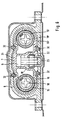
- Fig. 6 corresponds to a section along the line VI-VI, the is drawn in Fig. 3. From this figure the spatial nesting of the individual elements of the Roll bar out.
- the bow body 7 has as Extruded profile an approximately glasses-like shape. Here is one between the bracket legs 16 and 16 ' Connection wall arranged. This is opposite the Connection line of the two spring guide bolts 18 and 18 ' offset in parallel so that between the bracket legs 16 and 16 'the toothed segment 9 and the pawl 10 find space. This is also between the stirrup legs 16, 16 ' Unlocked release pawl 12 arranged.
- the mutually facing regions of the stirrup legs 16 and 16 ' are adapted in profile to the contour of the latch 10 and therefore lifted off the standpipes 15 and 15 '.
- the bracket body 7 is also in an extrusion process manufactured guide block 8, which , as already mentioned for FIG. 2, only over a partial area the axial length of the bracket body 7 extends.
- the Guide block 8 is provided with a recess in which the slidable guide elements 32 are inserted.
- This Guide elements 32 consist of one for such purposes usual material, such as PTFE.
- the section of Fig. 6 illustrates the type of attachment the latch 10 on the guide block 7. From the rear wall, so from the side of the vehicle rear wall, is in corresponding Recesses of the guide block 8, the latch housing 23 inserted, which with round, opposite Holes for the bearing pin 22 and for the Hinge pin 24 of the unlocking pawl 12 is provided. After inserting the latch housing 23 into the guide block 8 the pawl 10 and the release pawl 12 with attached their corresponding bolt. On the inside the connecting wall 31 of the bracket body 7 is between the Bracket legs 16 and 16 'riveted the toothed segment 9, which cooperates with the latch 10.
- the roll bar described is intended only in Driving out a crash. However, it is also possible to go through known measures by means of an electric motor or similar to set up an additional comfort drive.
Landscapes
- Engineering & Computer Science (AREA)
- Mechanical Engineering (AREA)
- Body Structure For Vehicles (AREA)
Description
- Fig. 1
- zeigt inen erfindungsgemäßen Überrollbügel mit einem Teil einer Sitzlehne in Seitenansicht,
- Fig. 2
- einen Längsschnitt durch einen Überrollbügel nach Fig. 1,
- Fig. 3
- einen Überrollbügel nach Fig.1 von vorne im Teilschnitt,
- Fig. 4
- einen Detailausschnitt aus Fig. 2 mit einer Auslöse- und Verriegelungsanordnung,
- Fig. 5a und 5b
- Detailausschnitte aus den Fig. 2 und 3 zur Befestigung einer Abdeckung am Überrollbügel
- und Fig. 6
- einen Querschnitt durch den erfindungsgemäßen Überrollbügel.
Claims (7)
- Ausfahrbarer Überrollbügel (1) für Cabriolet mit zwei parallel verlaufenden Bügelschenkeln (16,16') und einer Verriegelungs- und Auslösevorrichtung (10,9;12,13), dadurch gekennzeichnet, daß die Bügelschenkel (16,.16') durch eine Verbindungsplatte (31) über den größten Teil ihrer Länge miteinander verbunden sind.
- Überrollbügel nach Anspruch 1, dadurch gekennzeichnet, daß die Bügelschenkel (16,16') und die Verbindungsplatte (31) einstückig hergestellt sind und einen Bügelkörper (7) bilden.
- Überrollbügel nach Anspruch 2, dadurch gekennzeichnet, daß die einstückige Herstellung durch ein profilgebendes Verfahren erfolgt ist.
- Überrollbügel nach einem der vorhergehenden Ansprüche, dadurch gekennzeichnet, daß der Bügelkörper (7) von einer ortsfesten, einstückigen Außenführungsvorrichtung (8) über einen Teil seiner Länge umgeben ist.
- Überrollbügel nach einem der vorhergehenden Ansprüche, dadurch gekennzeichnet, daß die Bügelschenkel (16,16') und die Verbindungsplatte (31) zusammen ein etwa brillenförmiges Profil ergeben, wobei die Verbindungsplatte (31) gegenüber der Ebene der Mittelachsen der Bügelschenkel (16,16') parallel versetzt ist.
- Überrollbügel nach einem der vorhergehenden Ansprüche, dadurch gekennzeichnet, daß jeder Bügelschenkel (16,16') ein ortsfestes Standrohr (15,15') als Innenführung aufweist.
- Überrollbügel nach Anspruch 6, dadurch gekennzeichnet, daß die einander zugewandten Bereiche der Bügelschenkel (16,16') Spiel zu den Standrohren (15,15') aufweisen und in ihrem Profil der äußeren Abmessungen der Verriegelung- und Auslösevorrichtung angepaßt sind, welche zwischen den Bügelschenkeln angeordnet ist.
Applications Claiming Priority (2)
| Application Number | Priority Date | Filing Date | Title |
|---|---|---|---|
| DE19523790A DE19523790C2 (de) | 1995-07-04 | 1995-07-04 | Ausfahrbarer Überrollbügel |
| DE19523790 | 1995-07-04 |
Publications (2)
| Publication Number | Publication Date |
|---|---|
| EP0752344A1 EP0752344A1 (de) | 1997-01-08 |
| EP0752344B1 true EP0752344B1 (de) | 2000-04-26 |
Family
ID=7765630
Family Applications (1)
| Application Number | Title | Priority Date | Filing Date |
|---|---|---|---|
| EP96110454A Expired - Lifetime EP0752344B1 (de) | 1995-07-04 | 1996-06-28 | Ausfahrbarer Überrollbügel |
Country Status (2)
| Country | Link |
|---|---|
| EP (1) | EP0752344B1 (de) |
| DE (2) | DE19523790C2 (de) |
Families Citing this family (23)
| Publication number | Priority date | Publication date | Assignee | Title |
|---|---|---|---|---|
| DE19709908B4 (de) * | 1997-03-11 | 2004-05-06 | Ise Innomotive Systems Europe Gmbh | Verriegelungseinheit für einen im Crashfall ausgefahrenen Überrollbügel für Kraftfahrzeuge |
| DE19750457C2 (de) * | 1997-11-14 | 2000-08-10 | Ise Gmbh | Ausfahrbarer Überrollbügel für Kraftfahrzeuge |
| DE19750693C2 (de) * | 1997-11-15 | 2002-03-21 | Ise Gmbh | Ausfahrbarer Überrollbügel für Kraftfahrzeuge |
| DE19752484C2 (de) * | 1997-11-27 | 2000-08-10 | Ise Gmbh | Ausfahrbarer Überrollbügel für Kraftfahrzeuge |
| DE19803398A1 (de) * | 1998-01-29 | 1999-08-05 | Volkswagen Ag | Cabriolet mit Kopfstütze und Überrollschutz an mindestens einem Sitz |
| DE19838989C1 (de) * | 1998-08-27 | 1999-11-11 | Ise Gmbh | Überroll-Schutzvorrichtung |
| DE19910424C1 (de) * | 1999-03-10 | 2000-07-06 | Ise Gmbh | Überroll-Schutzvorrichtung für Kraftfahrzeuge |
| DE19949944C1 (de) * | 1999-10-16 | 2000-12-28 | Ise Gmbh | Haltevorrichtung für den Überrollkörper eines Überollschutzsystems |
| DE19952125C1 (de) * | 1999-10-29 | 2001-02-08 | Ise Gmbh | Überrollschutzsystem für Kraftfahrzeuge |
| DE10026978C1 (de) * | 2000-05-31 | 2001-10-18 | Ise Gmbh | Überrollschutzvorrichtung für Kraftfahrzeuge mit einer lektrisch verstellbaren Kopfstütze |
| DE10027753C1 (de) * | 2000-06-03 | 2001-09-06 | Ise Gmbh | Überrollschutzvorrichtung für Kraftfahrzeuge mit einem pyrotechnischen und einem weiteren, sich bei der Auslösung nicht verbrauchenden Aktuator |
| DE10044929C1 (de) * | 2000-09-12 | 2001-09-13 | Ise Gmbh | Überrollschutzsystem |
| DE10103247C1 (de) * | 2001-01-25 | 2002-02-21 | Ise Gmbh | Überrollschutzsystem für Kraftfahrzeuge |
| DE10132421C1 (de) | 2001-07-04 | 2002-07-25 | Ise Gmbh | Überrollschutzsystem für Kraftfahrzeuge |
| ES2225703T3 (es) | 2001-08-31 | 2005-03-16 | Ise Innomotive Systems Europe Gmbh | Sistema de proteccion antivuelco para vehiculos automoviles que comprende una parte de deformacion teorica. |
| EP1539543B1 (de) * | 2002-09-17 | 2007-08-22 | ISE Innomotive Systems Europe GmbH | Überrollschutzsystem für kraftfahrzeuge |
| FR2845047B1 (fr) * | 2002-09-30 | 2005-09-09 | Faurecia Sieges Automobile | Appui-tete de vehicule automobile pourvu d'un arceau de securite deployable |
| EP1518732A1 (de) * | 2003-09-24 | 2005-03-30 | Ford Global Technologies, LLC, A subsidary of Ford Motor Company | Windabweiser für ein Cabriolet-Fahrzeug |
| ATE460318T1 (de) | 2005-07-18 | 2010-03-15 | Norsk Hydro As | Überrollschutzsystem |
| DE102006023502B3 (de) | 2006-05-18 | 2008-02-07 | Automotive Group Ise Innomotive Systems Europe Gmbh | Überrollschutzsystem für Kraftfahrzeuge mit mindestens einem aktiv aufstellbaren Überrollkörper |
| DE102008000661A1 (de) | 2008-03-13 | 2009-09-24 | Euromotive Gmbh & Co. Kg | Ausfahrbarer Überrollschutz |
| DE102009000622A1 (de) | 2009-02-04 | 2010-08-12 | Alutech Gmbh | Klemmmechanismus und Überrollschutz mit ausfahrbarem Überrollkörper |
| DE102010036781A1 (de) | 2010-05-04 | 2011-11-10 | Alutech Gesellschaft M.B.H. | Verriegelungsvorrichtung für ein Überrollschutzsystem und Überrollschutzsystem mit einer Verriegelungsvorrichtung |
Family Cites Families (4)
| Publication number | Priority date | Publication date | Assignee | Title |
|---|---|---|---|---|
| US3292726A (en) * | 1964-12-21 | 1966-12-20 | Jr Emile Jette | Automobile safety device having roof reinforcing bar |
| DE4100506C1 (de) * | 1991-01-10 | 1992-05-21 | Mercedes-Benz Aktiengesellschaft, 7000 Stuttgart, De | |
| DE4302152C2 (de) * | 1993-01-27 | 2001-07-26 | Ise Gmbh | Mit einer Steuermutter versehener, elektrisch betätigter Komfortantrieb für Überrollbügel |
| DE4314538C3 (de) * | 1993-05-03 | 2000-11-09 | Bayerische Motoren Werke Ag | Überrollschutz-Vorrichtung für ein Kraftfahrzeug |
-
1995
- 1995-07-04 DE DE19523790A patent/DE19523790C2/de not_active Expired - Fee Related
-
1996
- 1996-06-28 EP EP96110454A patent/EP0752344B1/de not_active Expired - Lifetime
- 1996-06-28 DE DE59605026T patent/DE59605026D1/de not_active Expired - Lifetime
Also Published As
| Publication number | Publication date |
|---|---|
| DE59605026D1 (de) | 2000-05-31 |
| EP0752344A1 (de) | 1997-01-08 |
| DE19523790A1 (de) | 1997-01-09 |
| DE19523790C2 (de) | 2000-07-20 |
Similar Documents
| Publication | Publication Date | Title |
|---|---|---|
| DE19523790C2 (de) | Ausfahrbarer Überrollbügel | |
| EP2307259B1 (de) | Lenksäule für ein kraftfahrzeug | |
| DE69716445T2 (de) | Sitzrückenlehnemechanismus | |
| DE69600483T2 (de) | Dachgepäckträger für kraftfahrzeuge | |
| DE60113958T2 (de) | Kraftfahrzeugbremspedalanordnung | |
| DE4342400A1 (de) | Überrollbügeleinrichtung mit Innenführung und Außenführung | |
| DE19712955A1 (de) | Überrollschutzsystem für ein Fahrzeug, insbesondere für ein Cabriolet | |
| DE9321498U1 (de) | Überrollbügeleinrichtung mit Innenführung und Außenführung | |
| DE202005017077U1 (de) | Schiebetüranordnung für ein Kraftfahrzeug | |
| DE10241441A1 (de) | Fahrzeugsitz-Gestell und Sitz mit einem solchen Gestell | |
| EP1897761A2 (de) | Kraftfahrzeug mit einer Überrollbügelanordnung | |
| DE102007005517B4 (de) | Überrollschutzsystem für Kraftfahrzeuge mit einem aktiv aufstellbaren Überrollkörper mit integriertem Deformationselement | |
| EP1107878B1 (de) | Befestigungsvorrichtung für einen kindersitz | |
| DE69115918T2 (de) | Vorrichtung für fahrzeugladeplattformen mit rungenhaltern | |
| DE69704878T2 (de) | Vorrichtung für Fahrzeugsitzschiene mit Sekundärverriegelungssystem | |
| DE8107964U1 (de) | Vorrichtung zur selbsttaetigen verriegelung der schiebetuer eines fahrzeugs | |
| DE60302244T2 (de) | Pedalsicherheitssystem | |
| DE102006028664B4 (de) | Überrollschutzsystem für ein Kraftfahrzeug | |
| DE202008001132U1 (de) | Verstelleinrichtung | |
| DE102019200488A1 (de) | Lenksäule für ein Kraftfahrzeug | |
| DE102008060486A1 (de) | Stützrahmen zur Integration in die Rückenlehne eines Kraftfahrzeugsitzes und Kraftfahrzeugsitz mit einem solchen Stützrahmen | |
| EP1182097A2 (de) | Überrollschutzsystem | |
| EP1227011B1 (de) | Überrollschutzsystem für Kraftfahrzeuge | |
| EP0818371B1 (de) | Vorrichtung zur Befestigung eines Sicherheitsgurtes | |
| DE102009007742A1 (de) | Dachlastenträger für Kraftfahrzeuge |
Legal Events
| Date | Code | Title | Description |
|---|---|---|---|
| PUAI | Public reference made under article 153(3) epc to a published international application that has entered the european phase |
Free format text: ORIGINAL CODE: 0009012 |
|
| AK | Designated contracting states |
Kind code of ref document: A1 Designated state(s): DE FR GB IT |
|
| 17P | Request for examination filed |
Effective date: 19970708 |
|
| GRAG | Despatch of communication of intention to grant |
Free format text: ORIGINAL CODE: EPIDOS AGRA |
|
| 17Q | First examination report despatched |
Effective date: 19990517 |
|
| GRAG | Despatch of communication of intention to grant |
Free format text: ORIGINAL CODE: EPIDOS AGRA |
|
| GRAH | Despatch of communication of intention to grant a patent |
Free format text: ORIGINAL CODE: EPIDOS IGRA |
|
| RAP1 | Party data changed (applicant data changed or rights of an application transferred) |
Owner name: ISE INNOMOTIVE SYSTEMS EUROPE GMBH |
|
| GRAH | Despatch of communication of intention to grant a patent |
Free format text: ORIGINAL CODE: EPIDOS IGRA |
|
| GRAA | (expected) grant |
Free format text: ORIGINAL CODE: 0009210 |
|
| AK | Designated contracting states |
Kind code of ref document: B1 Designated state(s): DE FR GB IT |
|
| REF | Corresponds to: |
Ref document number: 59605026 Country of ref document: DE Date of ref document: 20000531 |
|
| ITF | It: translation for a ep patent filed | ||
| ET | Fr: translation filed | ||
| GBT | Gb: translation of ep patent filed (gb section 77(6)(a)/1977) |
Effective date: 20000726 |
|
| PLBE | No opposition filed within time limit |
Free format text: ORIGINAL CODE: 0009261 |
|
| STAA | Information on the status of an ep patent application or granted ep patent |
Free format text: STATUS: NO OPPOSITION FILED WITHIN TIME LIMIT |
|
| 26N | No opposition filed | ||
| REG | Reference to a national code |
Ref country code: GB Ref legal event code: IF02 |
|
| PGFP | Annual fee paid to national office [announced via postgrant information from national office to epo] |
Ref country code: FR Payment date: 20090618 Year of fee payment: 14 |
|
| PGFP | Annual fee paid to national office [announced via postgrant information from national office to epo] |
Ref country code: GB Payment date: 20090623 Year of fee payment: 14 |
|
| PGFP | Annual fee paid to national office [announced via postgrant information from national office to epo] |
Ref country code: IT Payment date: 20090626 Year of fee payment: 14 |
|
| GBPC | Gb: european patent ceased through non-payment of renewal fee |
Effective date: 20100628 |
|
| REG | Reference to a national code |
Ref country code: FR Ref legal event code: ST Effective date: 20110228 |
|
| PG25 | Lapsed in a contracting state [announced via postgrant information from national office to epo] |
Ref country code: IT Free format text: LAPSE BECAUSE OF NON-PAYMENT OF DUE FEES Effective date: 20100628 |
|
| PG25 | Lapsed in a contracting state [announced via postgrant information from national office to epo] |
Ref country code: FR Free format text: LAPSE BECAUSE OF NON-PAYMENT OF DUE FEES Effective date: 20100630 |
|
| PG25 | Lapsed in a contracting state [announced via postgrant information from national office to epo] |
Ref country code: GB Free format text: LAPSE BECAUSE OF NON-PAYMENT OF DUE FEES Effective date: 20100628 |
|
| REG | Reference to a national code |
Ref country code: DE Ref legal event code: R082 Ref document number: 59605026 Country of ref document: DE Representative=s name: KALKOFF & PARTNER PATENTANWAELTE, DE |
|
| REG | Reference to a national code |
Ref country code: DE Ref legal event code: R082 Ref document number: 59605026 Country of ref document: DE Representative=s name: REBBEREH, CORNELIA, DIPL.-ING., DE Effective date: 20130812 Ref country code: DE Ref legal event code: R082 Ref document number: 59605026 Country of ref document: DE Representative=s name: KALKOFF & PARTNER PATENTANWAELTE, DE Effective date: 20130812 Ref country code: DE Ref legal event code: R081 Ref document number: 59605026 Country of ref document: DE Owner name: METALSA AUTOMOTIVE GMBH, DE Free format text: FORMER OWNER: ISE AUTOMOTIVE GMBH, 51702 BERGNEUSTADT, DE Effective date: 20130812 |
|
| REG | Reference to a national code |
Ref country code: DE Ref legal event code: R082 Ref document number: 59605026 Country of ref document: DE Representative=s name: REBBEREH, CORNELIA, DIPL.-ING., DE |
|
| PGFP | Annual fee paid to national office [announced via postgrant information from national office to epo] |
Ref country code: DE Payment date: 20150612 Year of fee payment: 20 |
|
| REG | Reference to a national code |
Ref country code: DE Ref legal event code: R071 Ref document number: 59605026 Country of ref document: DE |