EP0751027A2 - Anordnung einer hydrodynamischen Kupplung in einem Antriebssystem - Google Patents
Anordnung einer hydrodynamischen Kupplung in einem Antriebssystem Download PDFInfo
- Publication number
- EP0751027A2 EP0751027A2 EP96109559A EP96109559A EP0751027A2 EP 0751027 A2 EP0751027 A2 EP 0751027A2 EP 96109559 A EP96109559 A EP 96109559A EP 96109559 A EP96109559 A EP 96109559A EP 0751027 A2 EP0751027 A2 EP 0751027A2
- Authority
- EP
- European Patent Office
- Prior art keywords
- output shaft
- arrangement
- bearing
- operating medium
- wheel
- Prior art date
- Legal status (The legal status is an assumption and is not a legal conclusion. Google has not performed a legal analysis and makes no representation as to the accuracy of the status listed.)
- Granted
Links
Images

Classifications
-
- F—MECHANICAL ENGINEERING; LIGHTING; HEATING; WEAPONS; BLASTING
- F16—ENGINEERING ELEMENTS AND UNITS; GENERAL MEASURES FOR PRODUCING AND MAINTAINING EFFECTIVE FUNCTIONING OF MACHINES OR INSTALLATIONS; THERMAL INSULATION IN GENERAL
- F16D—COUPLINGS FOR TRANSMITTING ROTATION; CLUTCHES; BRAKES
- F16D33/00—Rotary fluid couplings or clutches of the hydrokinetic type
- F16D33/06—Rotary fluid couplings or clutches of the hydrokinetic type controlled by changing the amount of liquid in the working circuit
-
- B—PERFORMING OPERATIONS; TRANSPORTING
- B60—VEHICLES IN GENERAL
- B60K—ARRANGEMENT OR MOUNTING OF PROPULSION UNITS OR OF TRANSMISSIONS IN VEHICLES; ARRANGEMENT OR MOUNTING OF PLURAL DIVERSE PRIME-MOVERS IN VEHICLES; AUXILIARY DRIVES FOR VEHICLES; INSTRUMENTATION OR DASHBOARDS FOR VEHICLES; ARRANGEMENTS IN CONNECTION WITH COOLING, AIR INTAKE, GAS EXHAUST OR FUEL SUPPLY OF PROPULSION UNITS IN VEHICLES
- B60K23/00—Arrangement or mounting of control devices for vehicle transmissions, or parts thereof, not otherwise provided for
- B60K23/02—Arrangement or mounting of control devices for vehicle transmissions, or parts thereof, not otherwise provided for for main transmission clutches
Definitions
- the invention relates to an arrangement of a hydrodynamic clutch in a drive system, in particular a turbo compound system, in detail with the features from the preamble of claim 1.
- an exhaust gas turbocharger for recovering energy from the exhaust gases of an internal combustion engine, which has a turbine driven by the engine exhaust gases and a compressor mechanically connected to it, and which pre-compresses the combustion air required for the engine.
- the exhaust gases themselves still have a high energy content after flowing out of the turbine.
- a second turbine driven by the exhaust gases which is switched in such a way that part of the residual energy is mechanically transmitted to the drive shaft of the internal combustion engine or a drive connected to it.
- the main bearings in a hydrodynamic clutch support the turbine wheel and the pump wheel on one side and the stationary part of the clutch on the other. Due to the constant rotation, the bearings, which support the turbine wheel with respect to the pump wheel, are only exposed to the slip between the pump wheel and the turbine wheel of the hydrodynamic clutch. These bearings, which support the turbine wheel with respect to the pump wheel, can therefore be referred to as low-speed bearings.
- the bearings, which support both the pump wheel and the turbine wheel in the stationary part of the clutch are constantly stressed during rotation, especially at higher speeds. These bearings are therefore called high-speed bearings.
- both low and high speed bearings are flooded with an oil / hydraulic fluid which is led into the working space of the clutch. Very large currents are therefore required for heat dissipation, since the heat accumulating on the bearings must also be dissipated.
- EP 0 507 887 B1 therefore discloses an arrangement for effectively supplying oil to a working chamber in a hydrodynamic coupling through which oil flows and for lubricating the bearings of the coupling, the oil supply of which is brought about by a channel in the stationary part of the coupling which leads into a room the clutch upstream one opens first bearing, through which the pump wheel is mounted in the impeller of the clutch, the oil after flowing through the first bearing reaches the working chamber of the clutch containing the pump wheel and the impeller.
- a second bearing is arranged in one of the wheels of the clutch, which is connected to the space upstream of the first bearing via a throttle, the throttle sealing against the main oil flow to the clutch and only an oil quantity sufficient for flow lubrication of the second bearing lets through.
- Such an arrangement is characterized by an enormous design effort.
- One bearing is completely flooded for the supply of operating media, while a partial flow for lubrication is branched off for the other bearing via a throttle. Due to this arrangement and a complicated operating medium supply channel routing due to the operating medium routing from a stationary component to a rotating component, a number of additional sealing measures are required.
- the invention is therefore based on the object of further developing a hydrodynamic coupling for use in a drive system, in particular a turbo compound system, in such a way that a simple supply of operating fluid takes place and no separate supply line is required for the lubricant supply to the bearings.
- the heat generated in the clutch due to the torque transmission should be able to be dissipated again without great effort.
- the primary, ie the pump wheel of the hydrodynamic clutch is supported on the output shaft of the clutch, with which the secondary or the turbine wheel can be connected in a rotationally fixed manner.
- the support is preferably provided via a bearing arrangement, comprising at least one bearing, preferably two bearings, with angular contact ball bearings preferably being used for combined loads due to the good absorption capacity.
- the angular contact ball bearings are arranged side by side in pairs. The arrangement of this storage takes place in the radial direction below the work space part described by the pump impeller.
- the bearing arrangement is preferably arranged in the region of the parting plane, which is formed by the blading of the pump wheel and turbine wheel.
- a central bore extending through the output shaft is provided for the supply of operating media, from which distribution channels extend in the radial direction in the circumferential direction of the output shaft. These are preferably arranged in the installed position of the clutch in such a way that they are also in the region of the parting plane between the turbine and pump wheel.
- the distribution channels open into a feed space described by the pump and turbine wheel in the installed position and upstream of the toroidal working space. As already mentioned, this is essentially limited in the axial direction by the turbine wheel and on the side of the pump wheel by the bearing arrangement.
- Corresponding means are provided in the equipment supply space to implement a partial flow branch for the bearing arrangement. These can be designed, for example, in the form of a disk with an inner contour that is bevelled in cross section. The resulting passage serves to meter the lubricant flow through the bearings.
- the solution according to the invention is characterized by a simple structure, in particular a simple supply of operating media with a simple channel guide, with a branching possibility for the supply of lubricant to the bearings at the same time in the operating equipment supply system is provided.
- Complex sealing measures can be omitted.
- the equipment is supplied during operation via rotating machine parts. Additional sealing measures are not necessary.
- the solution according to the invention is very simple to implement in terms of production technology and is therefore inexpensive. Furthermore, it is characterized by simple assembly and thus also later interchangeability.
- the equipment When the equipment is heated, it can be discharged through openings in the turbine wheel and replaced with new equipment which is fed back into the work area via the central feed line through the output shaft.
- this percentage can be kept as low as necessary in relation to the operating resources present in the work space.
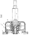
- FIG. 1 illustrates a hydrodynamic clutch 1 belonging to the power transmission in detail.
- the hydrodynamic clutch 1 comprises a primary wheel, which is referred to as pump wheel 2, and a secondary wheel, which becomes effective as a turbine wheel and which is designated by reference number 3.
- Pump and turbine wheel together form a toroidal working space 4, which can be filled with operating fluid, for example with oil.
- the pump wheel is driven by a gearwheel arranged on a shaft, not shown here, of a drive turbine, not shown here.
- this gearwheel meshes with a gearwheel 5 which is coupled in a rotationally fixed manner to the pump wheel 2.
- the secondary wheel or turbine wheel 3 is arranged on an output shaft 6 of the hydrodynamic clutch 1.
- the turbine wheel 3 is coupled in a rotationally fixed manner to the output shaft 6 by means of force or positive connections in the form of screw connections, here the screw connections 7 and 8.
- the power transmitted to the output shaft 6 via the hydrodynamic clutch 1 is transferred to a power transmission unit, the power transferred to the power transmission unit via the output shaft 6 being added to the power on the output shaft of a drive machine (not shown here) in the area of the power transmission unit.
- the gear wheel 5 are mounted on the output shaft 6 via a bearing 9, which is designed, for example, as a ball bearing, and the pump wheel 2 via an arrangement comprising a sleeve 10 and a bearing arrangement 11.
- the bearing arrangement 11 comprises two angular contact ball bearings 12 or 13. These enable combined loads, ie radial and axial forces, to be better absorbed than deep groove ball bearings.
- the pump wheel 2 is supported on the output shaft 6 via the sleeve 10 and the two angular contact ball bearings 12 and 13.
- the inner rings 14 and 15 of the angular contact ball bearings 12 and 13 of the bearing arrangement 11 are arranged directly on the output shaft 6.
- the outer rings 16 and 17 of the angular contact ball bearings 12 and 13 of the bearing arrangement 11 are supported on the inside 18 of the sleeve 10.
- the primary wheel 2 is in contact with the outside 19 of the sleeve 10.
- the pump wheel 2, sleeve 10 and the outer rings 16 and 17 of the angular contact ball bearings 12 and 13 are rotated at the same speed.
- press fits are provided between the outer rings 16 and 17 and the sleeve 10 and the outside 19 of the sleeve 10 and the impeller 2. The same applies to the support of the gear wheel 5 via the bearing 9 on the output shaft 6.
- the output shaft 6 has a bore 20, which is preferably arranged coaxially with the axis of symmetry A of the output shaft 6. This bore extends from the primary side to approximately the plane through the toroidal workspace through the perpendicular. Distribution bores 21 and 22 extend from this central bore 20 and extend from the central bore 20 to the outer circumference 23 of the output shaft 6 in the radial direction.
- the operating fluid is conducted into the toroidal working space 4 via the central bore 20 and the distribution bores 21 and 22. At the same time, the oil flow for the bearing arrangement 11 is branched off.
- a disk 24 is arranged between the pump wheel 2 and the primary wheel 3, which has a beveled one Has inner contour 25, which acts as a peeling edge for equipment.
- the chamfered inner contour extends from the feed chamber 26 to the outer rings 16 and 17 of the angular contact ball bearings 12 and 13 of the bearing arrangement 11.
- the two angular contact ball bearings 12 and 13 are completely flooded.
- the size of the branched operating medium flow can be influenced. This means that only a central supply of operating equipment and thus also a supply of lubricant is required. With a corresponding configuration, there is also the possibility of supplying the bearing 9, which serves to support the gear wheel 5 on the output shaft 6, with lubricant.
- the hydrodynamic coupling 1 is enclosed by a bell-shaped housing 27.
- This is preferably designed as a deep-drawn part and fastened to the gear 5 by means of various connection options. This makes it possible to manufacture the bell-shaped housing 27 as a deep-drawn part and, for example, to attach it to the toothed wheel 5 by means of welded or tacked connections.
- FIG. 2 shows an embodiment similar to that in FIG. 1, which is why the same reference numerals have been used for the same elements.
- the pump wheel of the hydrodynamic clutch 1 is also supported here on the output shaft 6 of the hydrodynamic clutch via a bearing arrangement 11, comprising two angular contact ball bearings 12 and 13 arranged in pairs.
- the pump wheel 2 is also connected in a rotationally fixed manner to a gear wheel 5, here via the screw connections 7 and 8.
- the gear wheel 5 is supported in part on the angular contact ball bearing 13.
- the turbine wheel 3 is non-rotatably coupled to the output shaft 6 via a spline connection 30.
- the working space 4 is supplied with operating fluid via a Central bore 20, which extends from the secondary side, ie from the side of the turbine wheel 3, in the direction of the primary side, ie in the direction of the pump wheel 2, of the hydrodynamic coupling 1 through the output shaft 6.
- Distribution channels 31 and 32 extend from this central bore 20 in the radial direction to the outer circumference 23 of the output shaft 6.
- the distribution channels 31 and 32 are arranged in such a way that they are arranged radially below the pump wheel 2, in particular the operating medium supply space 26, in the axial direction.
- the operating fluid flows from the operating medium supply space 26 directly to the bearings 12 and 13 of the bearing arrangement 11. Also in this case, an operating medium flow for lubricating the bearings is branched off from the operating medium chamber 26, which opens into the working chamber 4.
- further distribution channels 33 and 34 are provided, which can supply another bearing 35 with lubricant from the central bore 20.
- this bearing 35 can supply this bearing 35 from the branched flow of operating fluid from the supply space 26.
- a connection between the bearing 13 of the bearing arrangement 11 and the bearing 35 is required.
- the three bearings could be supplied from a branched flow of equipment.
- the bell-shaped clutch housing 27 is arranged and designed here in such a way that it is connected directly to the primary wheel.
- the bell-shaped coupling housing 27 is designed as a deep-drawn part.
- the turbine wheel 3 is constructed and constructed in such a way that, in the installed position, it has ribs projecting into the operating medium supply space 26. These are arranged in such a way that they are at certain intervals on one common diameter are arranged in the lubricant supply space.
- the arrangement of the operating medium supply space 26 also makes it possible to lubricate the spline connection between the turbine wheel 3 and the output shaft 6.
Landscapes
- Engineering & Computer Science (AREA)
- Mechanical Engineering (AREA)
- General Engineering & Computer Science (AREA)
- Chemical & Material Sciences (AREA)
- Combustion & Propulsion (AREA)
- Transportation (AREA)
- General Details Of Gearings (AREA)
- Rolling Contact Bearings (AREA)
- Support Of The Bearing (AREA)
- Supercharger (AREA)
Abstract
die hydrodynamische Kupplung umfaßt ein Pumpenrad und ein Turbinenrad, welche miteinander einen torusförmigen Arbeitsraum bilden;
das Turbinenrad ist mit einer Abtriebswelle drehfest verbunden;
dem torusförmigen Arbeitsraum ist ein Betriebsmittelzufuhrsystem zugeordnet.
das Pumpenrad stützt sich über eine Lageranordnung auf der Abtriebswelle ab;
das Betriebsmittelzufuhrsystem umfaßt:
einen Betriebsmittelzufuhrraum, welcher radial unterhalb des torusförmigen Arbeitsraumes angeordnet ist und in axialer Richtung von der Lageranordnung und der Kontur des Turbinenrades begrenzt wird;
einen zentralen Betriebsmittelzufuhrkanal, welcher in der Abtriebswelle angeordnet ist und sich in der Abtriebswelle in axialer Richtung wenigstens bis in den Bereich der Mittelebene der Kupplung erstreckt;
wenigstens einen Verteilkanal, welcher den zentralen Betriebsmittelzufuhrkanal mit dem Betriebsmittelzufuhrraum verbindet.
Description
- Die Erfindung betrifft eine Anordnung einer hydrodynamischen Kupplung in einem Antriebssystem, insbesondere einem Turbocompoundsystem, im einzelnen mit den Merkmalen aus dem Oberbegriff des Anspruchs 1.
- Bei Turbocompoundsystemen wird zur Rückgewinnung von Energie aus den Abgasen eines Verbrennungsmotors ein Abgasturbolader vorgesehen, der eine von den Motorabgasen angetriebene Turbine und einen mit dieser mechanisch verbundenen Verdichter aufweist, und der die für den Motor erforderliche Verbrennungsluft vorverdichtet. Die Abgase selbst besitzen nach dem Ausströmen aus der Turbine noch einen hohen Energiegehalt. Um diese Restenergie nutzbar zu machen, besteht die Möglichkeit, der Turbine des Abgasturboladers eine zweite, von den Abgasen angetriebene Turbine nachzuordnen, die so geschaltet wird, daß ein Teil der Restenergie mechanisch auf die Antriebswelle des Verbrennungsmotors oder einen damit verbundenen Antrieb überträgt.
- Derartige Systeme sind beispielsweise aus den folgenden Druckschriften bekannt:
- 1. US-PS 4,586,337
- 2. WO 86/00665
- Diese beiden Schriften zeigen Abgasturbinen, die über eine hydrodynamische Kupplung aus den Abgasen eines Verbrennungsmotors gewonnene Energie auf ein Steuerungsrad des Motors übertragen und für eine Schwingungsentkopplung zwischen Motor und Abgasturbine sorgen.
- Bei diesen Turbocompoundsystemen ist es wichtig, die Verluste in der Übertragung zwischen der Abgasturbine und der Kurbelwelle zu minimieren, um zu sichern, daß die Restenergie eine wirklich zusätzliche Antriebskraft auf die Kurbelwelle überträgt. Es ist vorteilhaft, das Schmiermittel des Motors als Betriebsmittel der hydrodynamischen Kupplung zu verwenden. In diesem Fall können Lager der hydrodynamischen Kupplung gleichzeitig geschmiert werden, und die Motorölpumpe kann zum Füllen der hydrodynamischen Kupplung genutzt werden, und gleichzeitig kann mit dem Schmiermittel bei ständiger Durchströmung die erzeugte Hitze abgeführt werden.
- Die Hauptlager in einer hydrodynamischen Kupplung tragen auf der einen Seite das Turbinenrad und das Pumpenrad und auf der anderen den stationären Teil der Kupplung. Aufgrund der ständigen Rotation sind die Lager, welche das Turbinenrad gegenüber dem Pumpenrad abstützen, nur dem Schlupf zwischen dem Pumpen- und dem Turbinenrad der hydrodynamischen Kupplung ausgesetzt. Diese Lager, welche das Turbinenrad gegenüber dem Pumpenrad abstützen, können deshalb als Niedriggeschwindigkeitslager bezeichnet werden. Die Lager, welche sowohl das Pumpenrad oder das Turbinenrad im stationären Teil der Kupplung abstützen, werden ständig beansprucht bei Rotation, insbesondere bei höheren Drehzahlen. Diese Lager werden deshalb Hochgeschwindigkeitslager genannt. In den Druckschriften US 3,058,296 und US 3,136,129 sind beide - Niedrig- und Hochgeschwindigkeitslager - geflutet mit einem Öl/Hydraulikfluid, welches in den Arbeitsraum der Kupplung geleitet wird. Zur Wärmeabfuhr sind somit sehr große Ströme erforderlich, da auch die an den Lagern anfallende Wärme abgeführt werden muß.
- Aus der EP 0 507 887 B1 ist deshalb eine Anordnung zur effektiven Ölversorgung einer Arbeitskammer in einer mit Öl durchströmten hydrodynamischen Kupplung und zur Schmierung der Lager der Kupplung bekannt, deren Ölversorgung durch einen Kanal in dem stehenden Teil der Kupplung bewirkt wird, der in einen Raum der Kupplung stromaufwärts eines ersten Lagers mündet, durch welches das Pumpenrad im Laufrad der Kupplung gelagert ist, wobei das Öl nach Durchströmen des ersten Lagers die das Pumpenrad und das Laufrad enthaltende Arbeitskammer der Kupplung erreicht. Zur Lagerung im Gehäuse ist in einem der Räder der Kupplung ein zweites Lager angeordnet, welches mit dem Raum stromaufwärts des ersten Lagers über eine Drossel in Verbindung steht, wobei die Drossel gegen den Hauptölstrom zur Kupplung abdichtet und nur eine zur Durchflußschmierung des zweiten Lagers ausreichende Ölmenge durchläßt. Eine derartige Anordnung zeichnet sich durch einen enormen konstruktiven Aufwand aus. Zur Betriebsmittelzufuhr wird das eine Lager vollständig geflutet, während für das andere Lager über eine Drossel ein Teilstrom zur Schmierung abgezweigt wird. Aufgrund dieser Anordnung und einer komplizierten Betriebsmittelzufuhrkanalführung aufgrund der Betriebsmittelführung von einem ruhenden Bauteil zu einem rotierenden Bauteil sind eine Reihe zusätzlicher Dichtmaßnahmen erforderlich.
- Der Erfindung liegt deshalb die Aufgabe zugrunde, eine hydrodynamische Kupplung für den Einsatz in einem Antriebssystem, insbesondere Turbocompoundsystem, derart weiterzuentwickeln, daß eine einfache Betriebsmittelzufuhr erfolgt und für die Schmiermittelzufuhr der Lager keine separate Versorgungsleitung erforderlich ist. Die aufgrund der Drehmomentenübertragung in der Kupplung anfallende Wärme soll ohne größeren Aufwand wieder abgeführt werden können.
- Die erfindungsgemäße Lösung ist durch die kennzeichnenden Merkmale des Anspruches 1 charakterisiert. Vorteilhafte Ausgestaltungen sind in den Unteransprüchen wiedergegeben.
- Erfindungsgemäß erfolgt die Abstützung des Primär-, d.h. des Pumpenrades der hydrodynamischen Kupplung auf der Abtriebswelle der Kupplung, mit welcher das Sekundär- bzw. das Turbinenrad drehfest verbindbar ist. Die Abstützung erfolgt dabei vorzugsweise über eine Lageranordnung, umfassend wenigstens ein Lager, vorzugsweise zwei Lager, wobei vorzugsweise aufgrund der guten Aufnahmefähigkeit für kombinierte Belastungen Schrägkugellager verwendet werden. Die Schrägkugellager werden dabei paarweise nebeneinander angeordnet. Die Anordnung dieser Lagerung erfolgt dabei in radialer Richtung unterhalb des vom Pumpenrad beschriebenen Arbeitsraumteiles. In axialer Richtung in Einbaulage betrachtet erfolgt die Anordnung der Lagerung vorzugsweise im Bereich der Trennebene, welche von der Beschaufelung von Pumpenrad und Turbinenrad gebildet wird. Zur Betriebsmittelversorgung ist eine sich durch die Abtriebswelle erstreckende Zentralbohrung vorgesehen, von welcher sich in radialer Richtung in Umfangsrichtung der Abtriebswelle Verteilkanäle erstrecken. Diese sind vorzugsweise in Einbaulage der Kupplung derart angeordnet, daß diese ebenfalls im Bereich der Trennebene zwischen Turbinen- und Pumpenrad liegen. Die Verteilkanäle münden in einen von Pumpen- und Turbinenrad in Einbaulage beschriebenen und dem torusförmigen Arbeitsraum vorgelagerten Zufuhrraum. Dieser wird, wie bereits erwähnt, in axialer Richtung vom Turbinenrad sowie auf seiten des Pumpenrades im wesentlichen von der Lageranordnung begrenzt. Zur Realisierung einer Teilstromabzweigung für die Lageranordnung sind entsprechende Mittel im Betriebsmittelzufuhrraum vorgesehen. Diese können beispielsweise in Form einer Scheibe mit im Querschnitt abgeschrägter Innenkontur ausgeführt sein. Der dadurch entstehende Durchlaß dient der Dosierung des Schmiermittelflusses durch die Lager.
- Die erfindungsgemäße Lösung zeichnet sich durch einen einfachen Aufbau aus, insbesondere einer einfachen Betriebsmittelzufuhr mit einfacher Kanalführung, wobei im Betriebsmittelzufuhrsystem gleichzeitig eine Abzweigmöglichkeit für die Schmiermittelzufuhr der Lager vorgesehen ist. Aufwendige Dichtungsmaßnahmen können entfallen. Die Betriebsmittelzufuhr erfolgt hier im Betrieb über rotierende Maschinenteile. Zusätzliche Dichtmaßnahmen sind nicht erforderlich. Die erfindungsgemäße Lösung ist fertigungstechnisch sehr einfach realisierbar und damit kostengünstig. Des weiteren zeichnet sie sich durch eine einfache Montage und damit auch spätere Austauschbarkeit aus.
- Vorteilhafterweise besteht auch die Möglichkeit, bei Abzweigung des Teilstromes für die Lageranordnung zur Abstützung des Pumpenrades diesen Teilstrom auch zur Schmierung benachbarter in axialer Richtung im Bereich der Lageranordnung angeordneter Lager zu nutzen. Dazu können einfache Verbindungsleitungen bzw. Bohrungen oder Öffnungen genutzt werden.
- Bei Erwärmung des Betriebsmittels kann dieses über Öffnungen am Turbinenrad abgeführt und durch neues Betriebsmittel, welches über die zentrale Zufuhrleitung durch die Abtriebswelle dem Arbeitsraum wieder zugeführt wird, ersetzt werden.
- Bei entsprechender Lageranordnung und Anordnung der Mittel zur Dosierung des Teilstromes kann dieser prozentual gegenüber dem im Arbeitsraum vorhandenen Betriebsmittel so gering wie nötig gehalten werden.
- Die erfindungsgemäße Lösung wird nachfolgend anhand von Figuren erläutert. Darin ist im übrigen folgendes dargestellt:
- Figur 1 zeigt eine erfindungsgemäße Ausführung einer Anordnung einer hydrodynamischen Kupplung in einem Turbocompoundsystem mit einer eine Abschälkante bildenden Scheibe im Betriebsmittelzufuhrraum;
- Figur 2 verdeutlicht eine weitere erfindungsgemäße Ausführung für die Anordnung einer hydrodynamischen Kupplung.
- Die Figur 1 verdeutlicht eine zur Kraftübertragung gehörende hydrodynamische Kupplung 1 im Detail. Die hydrodynamische Kupplung 1 umfaßt ein Primärrad, welches als Pumpenrad 2 bezeichnet wird, und ein als Turbinenrad wirksam werdendes Sekundärrad, das mit der Bezugsziffer 3 bezeichnet ist. Pumpen- und Turbinenrad bilden miteinander einen torusförmigen Arbeitsraum 4, welcher mit Betriebsfluid, beispielsweise mit Öl befüllbar ist. Das Pumpenrad wird von einem auf einer hier nicht dargestellten Welle einer hier nicht dargestellten Antriebsturbine angeordnet Zahnrad angetrieben. Zu diesem Zweck kämmt dieses Zahnrad mit einem drehfest mit dem Pumpenrad 2 gekoppelten Zahnrad 5.
- Das Sekundärrad bzw. Turbinenrad 3 ist auf einer Abtriebswelle 6 der hydrodynamischen Kupplung 1 angeordnet. Im dargestellten Ausführungsbeispiel ist das Turbinenrad 3 mit der Abtriebswelle 6 drehfest mittels Kraft bzw. formschlüssiger Verbindungen in Form von Schraubenverbindungen, hier stellvertretend die Schraubverbindungen 7 und 8, gekoppelt. Die über die hydrodynamische Kupplung 1 auf die Abtriebswelle 6 übertragene Leistung wird an eine Kraftübertragungseinheit übertragen, wobei die über die Abtriebswelle 6 auf die Kraftübertragungseinheit übertragene Leistung mit der Leistung an der Abtriebswelle einer hier nicht dargestellten Antriebsmaschine im Bereich der Kraftübertragungseinheit addiert wird. Des weiteren sind auf der Abtriebswelle 6 das Zahnrad 5 über ein Lager 9, welches beispielsweise als Kugellager ausgeführt ist, sowie das Pumpenrad 2 über eine Anordnung aus einer Hülse 10 und einer Lageranordnung 11 gelagert. Die Lageranordnung 11 umfaßt im dargestellten Fall zwei Schrägkugellager 12 bzw. 13. Diese ermöglichen es, kombinierte Belastungen, d.h. Radial- und Axialkräfte besser als Rillenkugellager aufzunehmen. Das Pumpenrad 2 stützt sich über die Hülse 10 und die beiden Schrägkugellager 12 und 13 an der Abtriebswelle 6 ab. Zu diesem Zweck sind die Innenringe 14 bzw. 15 der Schrägkugellager 12 bzw. 13 der Lageranordnung 11 direkt auf der Abtriebswelle 6 angeordnet. Die Außenringe 16 bzw. 17 der Schrägkugellager 12 bzw. 13 der Lageranordnung 11 stützen sich an der Innenseite 18 der Hülse 10 ab. Das Primärrad 2 steht mit der Außenseite 19 der Hülse 10 in Kontakt. Zur Realisierung der Drehmomentenaufnahme am Pumpenrad und Weitergabe über das Betriebsmittel an das Turbinenrad 3 erfolgen die Rotation von Pumpenrad 2, Hülse 10 und den Außenringen 16 und 17 der Schrägkugellager 12 und 13 mit gleicher Drehzahl. Zwischen den Außenringen 16 und 17 und der Hülse 10 sowie der Außenseite 19 der Hülse 10 und dem Pumpenrad 2 sind zu diesem Zweck Preßsitze vorgesehen. Analoges gilt für die Abstützung des Zahnrades 5 über das Lager 9 auf der Abtriebswelle 6.
- Die Ölversorgung des Arbeitsraumes erfolgt dabei direkt über die Abtriebswelle 6. Zu diesem Zweck weist die Abtriebswelle 6 eine Bohrung 20 auf, die vorzugsweise koaxial zur Symmetrieachse A der Abtriebswelle 6 angeordnet ist. Diese Bohrung erstreckt sich von der Primärseite bis in etwa zur durch die Mittelsenkrechte durch den torusförmigen Arbeitsraum gelegten Ebene. Von dieser Zentralbohrung 20 gehen Verteilbohrungen 21 und 22 ab, welche sich von der Zentralbohrung 20 bis an den Außenumfang 23 der Abtriebswelle 6 in radialer Richtung erstrecken. Über die Zentralbohrung 20 und die Verteilbohrungen 21 und 22 wird das Betriebsfluid in den torusförmigen Arbeitsraum 4 geleitet. Gleichzeitig erfolgt eine Abzweigung des Ölstromes für die Lageranordnung 11. Zu diesem Zweck ist zwischen dem Pumpenrad 2 und dem Primärrad 3 eine Scheibe 24 angeordnet, welche eine abgeschrägte Innenkontur 25 aufweist, die als Abschälkante für Betriebsmittel fungiert. Die abgeschrägte Innenkontur verläuft dabei vom Zufuhrraum 26 zu den Außenringen 16 und 17 der Schrägkugellager 12 bzw. 13 der Lageranordung 11 hin. Die beiden Schrägkugellager 12 bzw. 13 werden dabei vollständig geflutet. Entsprechend der Auslegung der Scheibe 24 kann auf die Größe des abgezweigten Betriebsmittelstromes Einfluß genommen werden. Es ist somit nur eine zentrale Betriebsmittelzufuhr und damit auch Schmiermittelzufuhr erforderlich. Bei entsprechender Ausgestaltung besteht auch die Möglichkeit, das Lager 9, welches der Abstützung des Zahnrades 5 an der Abtriebswelle 6 dient, mit Schmiermittel zu versorgen.
- Die hydrodynamische Kupplung 1 wird von einem glockenförmigen Gehäuse 27 umschlossen. Dieses ist vorzugsweise als Tiefziehteil ausgeführt und mittels verschiedener Verbindungsmöglichkeiten am Zahnrad 5 befestigt. Dadurch besteht die Möglichkeit, das glockenförmige Gehäuse 27 als ein Tiefziehteil herzustellen und beispielsweise mittels Schweiß- oder aber Heftverbindungen am Zahnrad 5 zu befestigen.
- In der Figur 2 ist eine ähnliche Ausführung wie in der Figur 1 dargestellt, weshalb für gleiche Elemente die gleichen Bezugszeichen verwendet wurden. Das Pumpenrad der hydrodynamischen Kupplung 1 stützt sich auch hier über eine Lageranordnung 11, umfassend zwei paarweise angeordnete Schrägkugellager 12 bzw. 13, auf der Abtriebswelle 6 der hydrodynamischen Kupplung ab. Das Pumpenrad 2 ist des weiteren drehfest mit einem Zahnrad 5 verbunden, hier über die Schraubverbindungen 7 bzw. 8. Das Zahnrad 5 stützt sich dabei zum Teil am Schrägkugellager 13 ab.
- Das Turbinenrad 3 ist über eine Keilwellenverbindung 30 mit der Abtriebswelle 6 drehfest gekoppelt. Die Versorgung des Arbeitsraumes 4 mit Betriebsfluid erfolgt über eine Zentralbohrung 20, welche sich von der Sekundärseite, d.h. von seiten des Turbinenrades 3, in Richtung Primärseite, d.h. in Richtung des Pumpenrades 2, der hydrodynamischen Kupplung 1 durch die Abtriebswelle 6 erstreckt. Von dieser zentralen Bohrung 20 erstrecken sich Verteilkanäle 31 und 32 in radialer Richtung zum Außenumfang 23 der Abtriebswelle 6. Die Verteilkanäle 31 und 32 sind dabei derart angeordnet, daß diese in axialer Richtung radial unterhalb des Pumpenrades 2, insbesondere des Betriebsmittelzufuhrraumes 26, angeordnet sind. Das Betriebsfluid gelangt vom Betriebsmittelzufuhrraum 26 direkt an die Lager 12 und 13 der Lageranordnung 11. Auch in diesem Fall wird ein Betriebsmittelstrom zur Schmierung der Lager vom Betriebsmittelraum 26, welcher in den Arbeitsraum 4 mündet, abgezweigt.
- In der dargestellten Ausführung sind weitere Verteilkanäle 33 und 34 vorgesehen, die ein weiteres Lager 35 von der Zentralbohrung 20 aus mit Schmiermittel versorgen können. In einer anderen hier nicht dargestellten Variante besteht die Möglichkeit, dieses Lager 35 ebenfalls vom abgezweigten Betriebsmittelstrom aus dem Zufuhrraum 26 zu versorgen. Zu diesem Zweck ist eine Verbindung zwischen dem Lager 13 der Lageranordnung 11 und dem Lager 35 erforderlich. Die drei Lager könnten in diesem Fall von einem abgezweigten Betriebsmittelstrom aus versorgt werden.
- Das glockenförmige Kupplungsgehäuse 27 ist hier derart angeordnet und ausgeführt, daß es direkt mit dem Primärrad verbunden ist. Auch hier ist das glockenförmige Kupplungsgehäuse 27 als Tiefziehteil ausgeführt.
- Das Turbinenrad 3 ist derart aufgebaut und ausgeführt, daß es in Einbaulage in den Betriebsmittelzufuhrraum 26 hineinragende Rippen aufweist. Diese sind derart angeordnet, daß sie sich in bestimmten Abständen auf einem gemeinsamen Durchmesser im Schmiermittelzufuhrraum angeordnet sind.
- Die Anordnung des Betriebsmittelzufuhrraumes 26 ermöglicht es auch, die Keilwellenverbindung zwischen Turbinenrad 3 und Abtriebswelle 6 zu schmieren.
Claims (6)
- Anordnung einer hydrodynamischen Kupplung in einem Antriebssystem, insbesondere einem Turbocompoundsystem;1.1 die hydrodynamische Kupplung umfaßt ein Pumpenrad und ein Turbinenrad, welche miteinander einen torusförmigen Arbeitsraum bilden;1.2 das Turbinenrad ist mit einer Abtriebswelle drehfest verbunden;1.3 dem torusförmigen Arbeitsraum ist ein Betriebsmittelzufuhrsystem zugeordnet; gekennzeichnet durch die folgenden Merkmale:1.4 das Pumpenrad stützt sich über eine Lageranordnung auf der Abtriebswelle ab;1.5 das Betriebsmittelzufuhrsystem umfaßt:1.5.1 einen Betriebsmittelzufuhrraum, welcher radial unterhalb des torusförmigen Arbeitsraumes angeordnet ist und in axialer Richtung von der Lageranordnung und der Kontur des Turbinenrades begrenzt wird;1.5.2 einen zentralen Betriebsmittelzufuhrkanal, welcher in der Abtriebswelle angeordnet ist und sich in der Abtriebswelle in axialer Richtung wenigstens bis in den Bereich der Mittelebene der Kupplung erstreckt;1.5.3 wenigstens einen Verteilkanal, welcher den zentralen Betriebsmittelzufuhrkanal mit dem Betriebsmittelzufuhrraum verbindet.
- Anordnung nach Anspruch 1, dadurch gekennzeichnet, daß im Betriebsmittelzufuhrraum Mittel vorgesehen sind, die eine dosierte Abzweigung eines Teilstromes zur Schmierung der Lageranordnung ermöglichen.
- Anordnung nach Anspruch 2, dadurch gekennzeichnet, daß das Mittel eine zur Lagerabstützung in axialer Richtung im Betriebsmittelzufuhrraum an den Außenring der Lageranordnung angrenzende Scheibe ist, welche eine in Richtung der Lager sich erweiternde Öffnung freigibt.
- Anordnung nach einem der Ansprüche 1 bis 3, dadurch gekennzeichnet, daß die Lageranordnung zwei nebeneinander angeordnete Wälzlager umfaßt.
- Anordnung nach Anspruch 4, dadurch gekennzeichnet, daß die beiden Wälzlager als Schrägkugellager ausgeführt sind.
- Anordnung nach einem der Ansprüche 1 bis 5, dadurch gekennzeichnet, daß ein weiteres Lager zur Abstützung der Abtriebswelle an einem Maschinenteil vorgesehen ist, welche mit der Lageranordnung über wenigstens einen Kanal zur Schmiermittelführung verbunden ist.
Applications Claiming Priority (2)
| Application Number | Priority Date | Filing Date | Title |
|---|---|---|---|
| DE19522753A DE19522753C2 (de) | 1995-06-26 | 1995-06-26 | Anordnung einer hydrodynamischen Kupplung in einem Antriebssystem |
| DE19522753 | 1995-06-26 |
Publications (3)
| Publication Number | Publication Date |
|---|---|
| EP0751027A2 true EP0751027A2 (de) | 1997-01-02 |
| EP0751027A3 EP0751027A3 (de) | 1997-08-20 |
| EP0751027B1 EP0751027B1 (de) | 2000-01-19 |
Family
ID=7765037
Family Applications (1)
| Application Number | Title | Priority Date | Filing Date |
|---|---|---|---|
| EP96109559A Expired - Lifetime EP0751027B1 (de) | 1995-06-26 | 1996-06-14 | Anordnung einer hydrodynamischen Kupplung in einem Antriebssystem |
Country Status (4)
| Country | Link |
|---|---|
| US (1) | US5778668A (de) |
| EP (1) | EP0751027B1 (de) |
| DE (2) | DE19522753C2 (de) |
| ES (1) | ES2143109T3 (de) |
Families Citing this family (12)
| Publication number | Priority date | Publication date | Assignee | Title |
|---|---|---|---|---|
| DE19802524B4 (de) * | 1998-01-26 | 2005-12-22 | Voith Turbo Gmbh & Co. Kg | Hydrodynamische Kupplung |
| DE59910503D1 (de) * | 1998-10-21 | 2004-10-21 | Voith Turbo Kg | Hydrodynamische Kupplung |
| DE102004064226B3 (de) | 2004-03-08 | 2020-01-23 | Voith Turbo Gmbh & Co. Kg | Turboverbundeinheit |
| EP1628024A3 (de) * | 2004-08-21 | 2009-07-29 | Khs Ag | Langzeit-Schmiersystem bei einem Lager für eine Welle |
| US7677041B2 (en) * | 2006-10-11 | 2010-03-16 | Woollenweber William E | Bearing systems for high-speed rotating machinery |
| DE102006053175A1 (de) * | 2006-11-09 | 2008-05-15 | Voith Patent Gmbh | Hydrodynamische Kupplung |
| DE102007062152A1 (de) | 2007-12-21 | 2009-06-25 | Bosch Mahle Turbo Systems Gmbh & Co. Kg | Welle |
| US8240443B2 (en) * | 2008-08-13 | 2012-08-14 | GM Global Technology Operations LLC | Powertrain with engine oil-fed torque converter |
| DE102011012861A1 (de) | 2011-03-02 | 2012-09-06 | Voith Patent Gmbh | Turbo-Compound-System, insbesondere eines Kraftfahrzeugs |
| DE102011115033B3 (de) * | 2011-10-07 | 2012-12-06 | Voith Patent Gmbh | Hydrodynamische Maschine |
| KR20200140504A (ko) * | 2019-06-07 | 2020-12-16 | 가부시키가이샤 미쯔이 이앤에스 머시너리 | 내연기관의 과급기 잉여동력 회수장치 및 선박 |
| EP4114313B1 (de) * | 2020-03-03 | 2025-10-01 | Shifamed Holdings, LLC | Herzklappenprothesenvorrichtungen und -systeme |
Family Cites Families (17)
| Publication number | Priority date | Publication date | Assignee | Title |
|---|---|---|---|---|
| US2430258A (en) * | 1940-02-05 | 1947-11-04 | Gen Motors Corp | Rotary hydraulic coupling of the turbine type |
| FR1005185A (fr) * | 1947-06-16 | 1952-04-07 | Dispositif d'alimentation des embrayages ou accouplements hydrauliques | |
| US3058296A (en) * | 1956-09-08 | 1962-10-16 | Daimler Benz Ag | Fan driving system including variable slip hydro-kinetic coupling |
| US3136129A (en) * | 1958-06-21 | 1964-06-09 | Daimler Benz Ag | Hydrodynamic coupling |
| DE7315939U (de) * | 1972-04-27 | 1973-08-09 | Francaise Du Ferodo Sa | Hydraulische Kupplungsvorrichtung |
| GB1424704A (en) * | 1972-04-27 | 1976-02-11 | Ferodo Sa | Hydraulic coupling device |
| US3952508A (en) * | 1975-03-31 | 1976-04-27 | Eaton Corporation | Control for fluid coupling |
| DE2909968C2 (de) * | 1979-03-14 | 1982-08-05 | Zahnradfabrik Friedrichshafen Ag, 7990 Friedrichshafen | Hydrodynamischer Trilok-Wandler |
| JPS5649426A (en) * | 1979-09-29 | 1981-05-06 | Daihatsu Motor Co Ltd | Device for feeding and draining working oil in fluid coupling |
| DE3212505A1 (de) * | 1982-04-03 | 1983-10-13 | KHD Canada Inc. Deutz R & D Devision, Montreal Quebec | Hydrodynamische kraftuebertragungsvorrichtung |
| SU1163066A1 (ru) * | 1983-07-26 | 1985-06-23 | Предприятие П/Я В-2964 | Пускотормозна гидродинамическа муфта |
| US4586337A (en) * | 1984-01-17 | 1986-05-06 | Cummins Engine Company, Inc. | Turbocompound system |
| AU571015B2 (en) * | 1984-07-13 | 1988-03-31 | Caterpillar Inc. | Turbocompound engine with turbine connected to timing gear |
| DE3434860A1 (de) * | 1984-09-22 | 1986-04-03 | Klöckner-Humboldt-Deutz AG, 5000 Köln | Hydrodynamische kupplung |
| SE465685B (sv) * | 1989-12-29 | 1991-10-14 | Saab Scania Ab | Arrangemang foer oljefoersoerjning till en arbetskammare i en av olja genomspolad hydrodynamisk koppling och smoerjning av kopplingens lager |
| JP3181586B2 (ja) * | 1990-10-10 | 2001-07-03 | ツァーンラトファブリック フリードリッヒシャーフェン アクチエン ゲゼルシャフト | 自動車のオートマチック・ギヤ変換機用のポンプ駆動装置 |
| SE9100571L (sv) * | 1991-02-28 | 1992-08-29 | Saab Scania Ab | Arrangemang vid hydrodynamisk koppling |
-
1995
- 1995-06-26 DE DE19522753A patent/DE19522753C2/de not_active Expired - Fee Related
-
1996
- 1996-06-14 ES ES96109559T patent/ES2143109T3/es not_active Expired - Lifetime
- 1996-06-14 DE DE59604209T patent/DE59604209D1/de not_active Expired - Lifetime
- 1996-06-14 EP EP96109559A patent/EP0751027B1/de not_active Expired - Lifetime
- 1996-06-24 US US08/669,217 patent/US5778668A/en not_active Expired - Lifetime
Also Published As
| Publication number | Publication date |
|---|---|
| DE19522753C2 (de) | 1999-08-12 |
| EP0751027A3 (de) | 1997-08-20 |
| ES2143109T3 (es) | 2000-05-01 |
| EP0751027B1 (de) | 2000-01-19 |
| DE59604209D1 (de) | 2000-02-24 |
| US5778668A (en) | 1998-07-14 |
| DE19522753A1 (de) | 1997-01-02 |
Similar Documents
| Publication | Publication Date | Title |
|---|---|---|
| DE3008949C2 (de) | Lageranordnung für eine mit hoher Drehzahl umlaufende Welle, insbesondere die Rotorwelle eines Turboladers | |
| DE102005012378A1 (de) | Elektromotor/Generator und Verfahren zum Kühlen eines elektromechanischen Getriebes | |
| DE69108523T2 (de) | Lager für Turbolader. | |
| EP0751027B1 (de) | Anordnung einer hydrodynamischen Kupplung in einem Antriebssystem | |
| DE112014002541B4 (de) | Leistungsübertragungsvorrichtung | |
| WO2012139820A2 (de) | Antriebsvorrichtung mit einer kühlbaren rotoranordnung | |
| EP2681428A1 (de) | Turbo-compound-system, insbesondere eines kraftfahrzeugs | |
| EP3929439A1 (de) | Axiale druckentlastung in gleitlagern von pumpen | |
| DE3338417C1 (de) | Planetenraeder-Hilfsgetriebe fuer ein Kraftfahrzeug | |
| DE68905003T2 (de) | Bremsmechanismus fuer fahrzeuge. | |
| EP0123989B1 (de) | Zentrigufal-Schmierölpumpe eines Abgasturboladers | |
| DE102005011889B4 (de) | Vorrichtung zum Kühlen und Schmieren eines Hybridgetriebes | |
| DE3612595A1 (de) | Turbomaschine | |
| WO2024099653A1 (de) | Differentialgetriebe für ein fahrzeug und antriebseinheit mit einer elektrischen maschine und einem differentialgetriebe | |
| DE1776234C3 (de) | Gasturbinenanlage zum Einbau in das Heck eines Personen- oder Kombikraftwagens oder Kleintransporters | |
| EP1761422B1 (de) | Retarder-rotationspumpen-baugruppe | |
| EP1697652B1 (de) | Hydrodynamische kupplung | |
| EP4305326B1 (de) | Übertragungsvorrichtung mit einer schwimmenden buchse für versorgungsmittel zwischen bauteilen eines planetengetriebes | |
| EP4504583A1 (de) | Antriebsbaugruppe für ein mit muskelkraft angetriebenes fahrzeug und fahrzeug mit einer solchen antriebsbaugruppe | |
| EP0995918B1 (de) | Hydrodynamische Kupplung | |
| DE102022004848B3 (de) | Elektrische Antriebsvorrichtung für ein Kraftfahrzeug, insbesondere für einen Kraftwagen, sowie Kraftfahrzeug | |
| WO2021018344A1 (de) | Elektrische antriebseinheit, hybridmodul und antriebsanordnung für ein kraftfahrzeug | |
| DE102023207499B3 (de) | Schmierung einer Passverzahnung am Ausgang eines Windkraftgetriebes | |
| DE202005003329U1 (de) | Retarder-Rotationspumpen-Baugruppe | |
| DE10253705B4 (de) | Schienenfahrzeug |
Legal Events
| Date | Code | Title | Description |
|---|---|---|---|
| PUAI | Public reference made under article 153(3) epc to a published international application that has entered the european phase |
Free format text: ORIGINAL CODE: 0009012 |
|
| AK | Designated contracting states |
Kind code of ref document: A2 Designated state(s): DE ES FR GB IT NL SE |
|
| PUAL | Search report despatched |
Free format text: ORIGINAL CODE: 0009013 |
|
| AK | Designated contracting states |
Kind code of ref document: A3 Designated state(s): DE ES FR GB IT NL SE |
|
| 17P | Request for examination filed |
Effective date: 19971111 |
|
| RAP1 | Party data changed (applicant data changed or rights of an application transferred) |
Owner name: VOITH TURBO BETEILIGUNGS GMBH |
|
| GRAG | Despatch of communication of intention to grant |
Free format text: ORIGINAL CODE: EPIDOS AGRA |
|
| 17Q | First examination report despatched |
Effective date: 19990312 |
|
| GRAG | Despatch of communication of intention to grant |
Free format text: ORIGINAL CODE: EPIDOS AGRA |
|
| GRAH | Despatch of communication of intention to grant a patent |
Free format text: ORIGINAL CODE: EPIDOS IGRA |
|
| GRAH | Despatch of communication of intention to grant a patent |
Free format text: ORIGINAL CODE: EPIDOS IGRA |
|
| GRAA | (expected) grant |
Free format text: ORIGINAL CODE: 0009210 |
|
| AK | Designated contracting states |
Kind code of ref document: B1 Designated state(s): DE ES FR GB IT NL SE |
|
| GBT | Gb: translation of ep patent filed (gb section 77(6)(a)/1977) |
Effective date: 20000119 |
|
| REF | Corresponds to: |
Ref document number: 59604209 Country of ref document: DE Date of ref document: 20000224 |
|
| ITF | It: translation for a ep patent filed | ||
| REG | Reference to a national code |
Ref country code: ES Ref legal event code: FG2A Ref document number: 2143109 Country of ref document: ES Kind code of ref document: T3 |
|
| ET | Fr: translation filed | ||
| PLBE | No opposition filed within time limit |
Free format text: ORIGINAL CODE: 0009261 |
|
| STAA | Information on the status of an ep patent application or granted ep patent |
Free format text: STATUS: NO OPPOSITION FILED WITHIN TIME LIMIT |
|
| 26N | No opposition filed | ||
| REG | Reference to a national code |
Ref country code: GB Ref legal event code: IF02 |
|
| GRAH | Despatch of communication of intention to grant a patent |
Free format text: ORIGINAL CODE: EPIDOS IGRA |
|
| PGFP | Annual fee paid to national office [announced via postgrant information from national office to epo] |
Ref country code: ES Payment date: 20070605 Year of fee payment: 12 |
|
| PGFP | Annual fee paid to national office [announced via postgrant information from national office to epo] |
Ref country code: NL Payment date: 20070627 Year of fee payment: 12 |
|
| PGFP | Annual fee paid to national office [announced via postgrant information from national office to epo] |
Ref country code: GB Payment date: 20070529 Year of fee payment: 12 |
|
| PGFP | Annual fee paid to national office [announced via postgrant information from national office to epo] |
Ref country code: FR Payment date: 20070625 Year of fee payment: 12 |
|
| GBPC | Gb: european patent ceased through non-payment of renewal fee |
Effective date: 20080614 |
|
| NLV4 | Nl: lapsed or anulled due to non-payment of the annual fee |
Effective date: 20090101 |
|
| REG | Reference to a national code |
Ref country code: FR Ref legal event code: ST Effective date: 20090228 |
|
| PG25 | Lapsed in a contracting state [announced via postgrant information from national office to epo] |
Ref country code: NL Free format text: LAPSE BECAUSE OF NON-PAYMENT OF DUE FEES Effective date: 20090101 |
|
| PG25 | Lapsed in a contracting state [announced via postgrant information from national office to epo] |
Ref country code: GB Free format text: LAPSE BECAUSE OF NON-PAYMENT OF DUE FEES Effective date: 20080614 |
|
| REG | Reference to a national code |
Ref country code: ES Ref legal event code: FD2A Effective date: 20080616 |
|
| PG25 | Lapsed in a contracting state [announced via postgrant information from national office to epo] |
Ref country code: FR Free format text: LAPSE BECAUSE OF NON-PAYMENT OF DUE FEES Effective date: 20080630 |
|
| PG25 | Lapsed in a contracting state [announced via postgrant information from national office to epo] |
Ref country code: ES Free format text: LAPSE BECAUSE OF NON-PAYMENT OF DUE FEES Effective date: 20080616 |
|
| PGFP | Annual fee paid to national office [announced via postgrant information from national office to epo] |
Ref country code: IT Payment date: 20100618 Year of fee payment: 15 |
|
| PG25 | Lapsed in a contracting state [announced via postgrant information from national office to epo] |
Ref country code: IT Free format text: LAPSE BECAUSE OF NON-PAYMENT OF DUE FEES Effective date: 20110614 |
|
| PGFP | Annual fee paid to national office [announced via postgrant information from national office to epo] |
Ref country code: SE Payment date: 20140623 Year of fee payment: 19 |
|
| PGFP | Annual fee paid to national office [announced via postgrant information from national office to epo] |
Ref country code: DE Payment date: 20150619 Year of fee payment: 20 |
|
| REG | Reference to a national code |
Ref country code: SE Ref legal event code: EUG |
|
| PG25 | Lapsed in a contracting state [announced via postgrant information from national office to epo] |
Ref country code: SE Free format text: LAPSE BECAUSE OF NON-PAYMENT OF DUE FEES Effective date: 20150615 |
|
| REG | Reference to a national code |
Ref country code: DE Ref legal event code: R071 Ref document number: 59604209 Country of ref document: DE |