EP0750864B1 - Flächenhaftverschluss - Google Patents
Flächenhaftverschluss Download PDFInfo
- Publication number
- EP0750864B1 EP0750864B1 EP96304802A EP96304802A EP0750864B1 EP 0750864 B1 EP0750864 B1 EP 0750864B1 EP 96304802 A EP96304802 A EP 96304802A EP 96304802 A EP96304802 A EP 96304802A EP 0750864 B1 EP0750864 B1 EP 0750864B1
- Authority
- EP
- European Patent Office
- Prior art keywords
- surface fastener
- round
- interlocking elements
- woven fabric
- woven
- Prior art date
- Legal status (The legal status is an assumption and is not a legal conclusion. Google has not performed a legal analysis and makes no representation as to the accuracy of the status listed.)
- Expired - Lifetime
Links
- 239000002759 woven fabric Substances 0.000 claims description 39
- 230000000295 complement effect Effects 0.000 claims 3
- 239000004744 fabric Substances 0.000 description 8
- 238000009958 sewing Methods 0.000 description 8
- 238000009941 weaving Methods 0.000 description 6
- 238000010409 ironing Methods 0.000 description 5
- 230000006835 compression Effects 0.000 description 3
- 238000007906 compression Methods 0.000 description 3
- 238000004519 manufacturing process Methods 0.000 description 3
- 238000000034 method Methods 0.000 description 2
- 239000004033 plastic Substances 0.000 description 2
- 229920003023 plastic Polymers 0.000 description 2
- 230000002035 prolonged effect Effects 0.000 description 2
- 229920003051 synthetic elastomer Polymers 0.000 description 2
- 229920003002 synthetic resin Polymers 0.000 description 2
- 239000000057 synthetic resin Substances 0.000 description 2
- 239000005061 synthetic rubber Substances 0.000 description 2
- 235000001674 Agaricus brunnescens Nutrition 0.000 description 1
- 239000004952 Polyamide Substances 0.000 description 1
- 239000000853 adhesive Substances 0.000 description 1
- 230000001788 irregular Effects 0.000 description 1
- 238000004900 laundering Methods 0.000 description 1
- 239000000463 material Substances 0.000 description 1
- 230000013011 mating Effects 0.000 description 1
- 239000000203 mixture Substances 0.000 description 1
- 238000012986 modification Methods 0.000 description 1
- 230000004048 modification Effects 0.000 description 1
- 229920002647 polyamide Polymers 0.000 description 1
- 229920000728 polyester Polymers 0.000 description 1
- 239000012209 synthetic fiber Substances 0.000 description 1
- 229920002994 synthetic fiber Polymers 0.000 description 1
- 238000004078 waterproofing Methods 0.000 description 1
Images

Classifications
-
- A—HUMAN NECESSITIES
- A44—HABERDASHERY; JEWELLERY
- A44B—BUTTONS, PINS, BUCKLES, SLIDE FASTENERS, OR THE LIKE
- A44B18/00—Fasteners of the touch-and-close type; Making such fasteners
- A44B18/0023—Woven or knitted fasteners
- A44B18/0034—Female or loop elements
-
- A—HUMAN NECESSITIES
- A44—HABERDASHERY; JEWELLERY
- A44B—BUTTONS, PINS, BUCKLES, SLIDE FASTENERS, OR THE LIKE
- A44B18/00—Fasteners of the touch-and-close type; Making such fasteners
-
- Y—GENERAL TAGGING OF NEW TECHNOLOGICAL DEVELOPMENTS; GENERAL TAGGING OF CROSS-SECTIONAL TECHNOLOGIES SPANNING OVER SEVERAL SECTIONS OF THE IPC; TECHNICAL SUBJECTS COVERED BY FORMER USPC CROSS-REFERENCE ART COLLECTIONS [XRACs] AND DIGESTS
- Y10—TECHNICAL SUBJECTS COVERED BY FORMER USPC
- Y10T—TECHNICAL SUBJECTS COVERED BY FORMER US CLASSIFICATION
- Y10T24/00—Buckles, buttons, clasps, etc.
- Y10T24/27—Buckles, buttons, clasps, etc. including readily dissociable fastener having numerous, protruding, unitary filaments randomly interlocking with, and simultaneously moving towards, mating structure [e.g., hook-loop type fastener]
- Y10T24/2742—Buckles, buttons, clasps, etc. including readily dissociable fastener having numerous, protruding, unitary filaments randomly interlocking with, and simultaneously moving towards, mating structure [e.g., hook-loop type fastener] having filaments of varied shape or size on same mounting surface
-
- Y—GENERAL TAGGING OF NEW TECHNOLOGICAL DEVELOPMENTS; GENERAL TAGGING OF CROSS-SECTIONAL TECHNOLOGIES SPANNING OVER SEVERAL SECTIONS OF THE IPC; TECHNICAL SUBJECTS COVERED BY FORMER USPC CROSS-REFERENCE ART COLLECTIONS [XRACs] AND DIGESTS
- Y10—TECHNICAL SUBJECTS COVERED BY FORMER USPC
- Y10T—TECHNICAL SUBJECTS COVERED BY FORMER US CLASSIFICATION
- Y10T428/00—Stock material or miscellaneous articles
- Y10T428/24—Structurally defined web or sheet [e.g., overall dimension, etc.]
- Y10T428/24008—Structurally defined web or sheet [e.g., overall dimension, etc.] including fastener for attaching to external surface
- Y10T428/24017—Hook or barb
-
- Y—GENERAL TAGGING OF NEW TECHNOLOGICAL DEVELOPMENTS; GENERAL TAGGING OF CROSS-SECTIONAL TECHNOLOGIES SPANNING OVER SEVERAL SECTIONS OF THE IPC; TECHNICAL SUBJECTS COVERED BY FORMER USPC CROSS-REFERENCE ART COLLECTIONS [XRACs] AND DIGESTS
- Y10—TECHNICAL SUBJECTS COVERED BY FORMER USPC
- Y10T—TECHNICAL SUBJECTS COVERED BY FORMER US CLASSIFICATION
- Y10T428/00—Stock material or miscellaneous articles
- Y10T428/24—Structurally defined web or sheet [e.g., overall dimension, etc.]
- Y10T428/24174—Structurally defined web or sheet [e.g., overall dimension, etc.] including sheet or component perpendicular to plane of web or sheet
- Y10T428/24182—Inward from edge of web or sheet
Definitions
- the present invention relates to a surface fastener capable of preventing a crushing of interlocking elements, such as loops or hooks, under pressure exerted by ironing, for example.
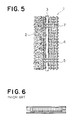
- Japanese Utility Model Laid-open Publication No. SHO 54-102305 discloses a conventional surface fastener composed of male and female fastener parts each including, as shown here in FIG. 6, a pair of waterproof members of synthetic resin or rubber woven into a foundation fabric along opposite longitudinal edges thereof to form thick and bulky woven longitudinal edge portions so as to provide a waterproofing design to the surface fastener.
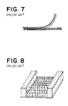
- Another conventional surface fastener disclosed in Japanese Utility Model Laid-open No. SHO 59-68410 includes, as shown here in FIG. 7, a pair of woven or knitted core members attached as bank-like projections sewn to opposite longitudinal edges of a foundation fabric of a female fastener part including a mass of loop-like interlocking elements implanted into the foundation fabric.
- Japanese Utility Model Publication No. HEI 6-37710 discloses a fastening device composed of a surface fastener which includes, as shown here in FIG. 8, a pair of cushioning members of sponge or foamed plastics disposed on one surface of a foundation fabric along opposite longitudinal edges thereof such that the cushioning members are normally higher than interlocking elements, such as loops or hooks, and become smaller in height than the interlocking elements when they are compressed.
- the waterproof members of synthetic resin or rubber are woven into the opposite longitudinal edges of the foundation fabric to form thick and bulky longitudinal edge portions so as to provide a waterproof design to the surface fastener.
- the thick and bulky longitudinal edge portions must project beyond an outer end of the interlocking elements, and so the interlocking elements are unable to engage with the mating interlocking elements with sufficient stability.
- Another problem is that the surface fastener has no particular mounting portion and hence cannot be readily attached to an article by a sewing means.
- the second-mentioned example of known surface fastener cannot be manufactured by a single operation and hence is expensive to manufacture because the woven or knitted core members are sewn to the longitudinal edges of the foundation fabric after the foundation fabric including the interlocking elements is manufactured. Due to the absence of a mounting portion, the surface fastener requires a tedious sewing operation when it is attached to an article by a sewing means.
- the third-mentioned example is a fastening device composed of a known surface fastener including the cushioning members of sponge or foamed plastic disposed on the opposite edges of one surface of the foundation fabric, and it cannot prevent a crushing of the interlocking elements, such as loops or hooks, when the surface fastener is subjected to ironing, for example.
- the fastening device composed of the surface fastener cannot be attached to an article by a sewing means and, hence, has a limited scope of application.
- EP-A-0 310 784 Another surface fastener is known from EP-A-0 310 784, which discloses the features of the preambles of claims 1 and 8.
- an object of the present invention is to provide a surface fastener which is capable of preventing a crushing of interlocking elements, such as loops, hooks, or the mushroom-typed when subjected to a pressure during ironing, for example, which can retain a strong engagement between two companion fastener parts and hence is applicable to various fields of use, and which can be manufactured by a single operation and hence is inexpensive to manufacture.
- the present invention provides a surface fastener which comprises: a woven fabric having a number of interlocking elements projecting from one surface of the woven fabric; at least one round cord disposed adjacent to the interlocking elements, the round cord being woven at regular intervals as the woven fabric is woven in such a condition that the round cord is longitudinally tensed to have a height smaller than the height of the interlocking elements and disposed in a exposed condition on the surface of the woven fabric.
- a flat attachment portion may be disposed on an outer side of the round cord where no interlocking elements are provided to facilitate sewing the fastener to an article.
- the surface fastener may have a single-row structure in which two round cords are disposed on opposite sides of one group of interlocking elements projecting from the surface of the woven fabric.
- the surface fastener may have a multi-row structure in which a plurality of groups of interlocking elements are disposed alternately with a plurality of round cords.
- each of the round cords is woven, as the woven fabric is woven, with a warp yarn (hereafter called "a binding yarn") under tensed condition such that the round cord is disposed in an exposed condition on the surface of the woven fabric.
- a warp yarn hereafter called "a binding yarn”
- each of the round cords is woven with a weft yarn of the woven fabric while the round cord is in tensed condition such that the round cord is disposed in an exposed condition on the surface of the woven fabric.
- the round cord is preferably composed of a braid or a knitted cord.
- the round cord is disposed in an exposed condition on a surface of the woven fabric adjacent to the interlocking elements, and since the round cord is woven under tensed condition, the round cord is rigid and is highly resistant to compression or crush. Accordingly, in the case where the surface fastener is used on a pillow cover of a vehicle seat, the round cord is able to prevent a crushing of the interlocking elements even when the surface fastener is subjected to wringing or ironing after the pillow cover is laundered. The interlocking elements kept free from crushing are able to provide a great fastening strength over a prolonged period of use.
- the flat attachment portion provided on the outer side of the round cord, the surface fastener can be readily attached to an article.
- the flat attachment portion may be omitted.
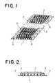
- a surface fastener includes, as shown in FIGS. 1 and 2, a woven fabric 1 having a mass of interlocking elements 2, such as hooks or loops (as in the illustrated embodiment), projecting from one surface of the woven fabric 1, and a pair of round cords 3, 3 disposed on the surface of the woven fabric 1 adjacent to opposite longitudinal edges of the mass of interlocking elements 2.
- the round cords 3, 3 are composed of a braid or a knitted cord and arranged in such a manner as shown in FIG. 3. As shown in FIG.
- the woven fabric 1 is woven of warp yarns 4 and a weft yarn 5, and at the time of weaving, the round cords 3 are prepared as warp yarns and each is woven under constant tension by binding with a binding yarn 6 at regular intervals in such a condition that the round cords 3 are disposed in an exposed condition on the surface of the woven fabric 1 and hence able to prevent a crushing of the interlocking elements 2.
- the interlocking elements 2 may have an arrangement composed of a mixture of hooks and loops.
- the woven fabric 1 has a flat longitudinal edge portion devoid of interlocking elements 2 and disposed in juxtaposition with each of the round cords 3 on an outer side of the round cord 3 where no interlocking elements 2 are provided.
- the flat longitudinal edge portion of the woven fabric 1 constitutes an attachment portion 7 which can be used for facilitating attachment of the surface fastener to an article by the use of a sewing means.
- the flat attachment portion 7 is formed at the same time as the woven fabric 1 is woven.
- the surface fastener may have a multi-row structure including a plurality (two being shown) of laterally spaced groups of interlocking elements 2 arranged alternately with a plurality (three being shown) of round cords 3 woven into the woven fabric 1.
- the multi-row structure is particularly suitable for use in a wide surface fastener.
- the round cords 3 are woven into the woven fabric 1 at desired transverse intervals which may be regular or irregular.
- the interlocking elements 2 composed of hooks or loops, the round cords 3, the warp yarns 4, the weft yarn 5, and the binding yarns 6 all used in the surface fastener are formed from a multifilament yarn or a monofilament yarn of synthetic fiber such as polyamide or polyester.
- the round cords 3 are composed of a braid or a knitted cord, as described above, and more particularly, a round braid is preferable.
- FIG. 5 shows a modified form of the surface fastener in which a round cord 3 is woven directly with a weft yarn 5 at regular intervals as a woven fabric 1 is woven on a needle loom.
- the round cord 3 is prepared as a warp yarn and woven under tensed condition so that the round cord 3 is disposed in an exposed condition on a surface of the woven fabric 1 and hence capable of preventing a crushing of the interlocking elements 2 composed of hooks or loops.
- a flat attachment portion 7 devoid of interlocking elements 2 is formed on an outer side of the round cord 3 opposite to the interlocking elements 2.
- the surface fasteners of the present invention have various advantages enumerated below.
- the round cords of the surface fastener are woven at regular intervals into the woven fabric along opposite longitudinal edges of a group of interlocking elements on the woven fabric in such a condition that the round cords are tensed and have a smaller height than the interlocking elements, the round cords are made rigid and highly resistant to compression or crush.
- the round cords are, therefore, possible to withstand a wringing operation and an ironing operation done after laundering. With the round cords thus provided, the interlocking elements are completely protected against crush and able to provide a great fastening strength over a prolonged period of use.
- the surface fastener of this invention can be readily and accurately and moreover neatly attached by sewing to an article by using the attachment portion rather than the interlocking elements used for sewing purposes in the case of a conventional surface fastener.
- the flat attachment portion may be omitted.
- the surface fastener of this invention can be secured onto the article using an adhesive agent.
- the surface fastener of the present invention can be manufactured by a single weaving operation which will bring a certain reduction in manufacturing cost.
- the surface fastener of this invention can, therefore, be manufactured at a low cost.
- the surface fastener of this invention may have a single-row structure in which two round cords are disposed on opposite sides of a group of interlocking elements, which structure is particularly useful when embodied in a narrow surface fastener because the interlocking elements are fully protected against compression or crush by means of the round cords.
- the surface fastener may also have a multi-row structure in which a plurality of laterally spaced groups of interlocking elements are disposed alternately with a plurality of round cords, which structure is particularly useful when the surface fastener is deformed in the transverse direction, and especially when it is applied for a wide surface fastener, the round cords are able to provide a sufficient protection to the interlocking elements against crush.
- the round cords are arranged as warp yarns and woven under tensed condition with binding yarns or a weft yarn so that the round cords are disposed in exposed condition on a surface of the woven fabric.
- the round cords thus arranged only requires a simple weaving operation and can provide aesthetical appearance to the surface fastener.
- the round cord is composed of a braid or a knitted cord, it can be manufactured with no difficulty.
- the round cords are composed of the same material as the woven fabric and hence fit well with the woven fabric, a weaving operation can be achieved smoothly and reliably.
- the shape of the interlocking elements of the invention is not limited to the hooks or loops and it may be a mushroom shape.
Landscapes
- Slide Fasteners, Snap Fasteners, And Hook Fasteners (AREA)
- Woven Fabrics (AREA)
Claims (8)
- Flächenhaftverschluß, welcher ein Gewebe (1) beinhaltet, das eine Anzahl von Verschlußelementen (2) aufweist, welche über eine einzige Oberfläche des Gewebes (1) überstehen, um mit einem ein Gegenstück bildenden Flächenhaftverschlußabschnitt in Eingriff zu kommen, und welcher weiter mindestens zwei Polsterelemente beinhaltet, die benachbart zu den Verschlußelementen angeordnet sind, geringere Höhe als diese Verschlußelemente (2) aufweisen und auf der Oberfläche des Gewebes (1) in ausgesetztem Zustand angeordnet sind, dadurch gekennzeichnet, daß es ich bei den Polsterelementen um runde Schnüre (3) handelt, die während des Webens des Gewebes (1) in regelmäßigen Abständen eingewebt sind, und zwar in einem solchen Zustand, daß die runden Schnüre in Längsrichtung gespannt sind.
- Flächenhaftverschluß nach Anspruch 1, bei welchem ebene Befestigungsabschnitte (7) auf äußeren Seiten der runden Schnüre (3), wo keine Verschlußelemente (2) vorgesehen sind, angeordnet sind.
- Flächenhaftverschluß nach Anspruch 1, bei welchem die runde Schnur (3) aus einer Paspel oder einer gewirkten Schnur besteht.
- Flächenhaftverschluß nach Anspruch 1, bei welchem die Anzahl der runden Schnüre (3) zwei beträgt, wobei zwei der runden Schnüre (3; 3) auf entgegengesetzten Seiten der Verschlußelemente (2) angeordnet sind und aus der einen Oberfläche des Gewebes (1) hervorstehen, und der Befestigungsabschnitt (7) auf den äußeren Seiten der runden Schnüre (3) angeordnet ist.
- Flächenhaftverschluß nach Anspruch 1, bei welchem die aus dieser einen Oberfläche des Gewebes (1) hervorstehenden Verschlußelemente (2) aus einer Mehrzahl von Gruppen von Verschlußelementen (2) besteht, die abwechselnd mit einer Mehrzahl von den runden Schnüren (3) angeordnet sind, wobei der Befestigungsabschnitt (7) neben jedem der am weitesten außen liegenden runden Schnüre (3) jeweils auf einer äußeren Seite dieser runden Schnüre (3) angeordnet ist.
- Flächenhaftverschluß nach einem der Ansprüche 1, 3, oder 4 , bei welchem jeder der runden Schnüre (3) mit einem in gespanntem Zustand befindlichen Bindegarn (3) gewebt ist, derart daß die runde Schnur (3) in ausgesetztem Zustand auf der einen Oberfläche des Gewebes (1) angeordnet ist.
- Flächenhaftverschluß nach einem der Ansprüche 1, 3, oder 4 , bei welchem jeder der runden Schnüre (3) mit einem in gespanntem Zustand befindlichen Schußgarn (5) des Gewebes (1) gewebt ist, derart daß die runde Schnur (3) in ausgesetztem Zustand auf der einen Oberfläche des Gewebes (1) angeordnet ist.
- Flächenhaftverschlußabschnitt, welcher eine Gewebebasis (1) beinhaltet, die eine Mehrzahl von Verschlußelementen (2) aufweist, welche über eine Oberfläche der Basis (1) überstehen, um mit einem ein Gegenstück bildenden Flächenhaftverschlußabschnitt in Eingriff zu kommen, und welcher weiter ein Polsterelement beinhaltet, das benachbart zu diesen Elementen angeordnet ist und ein niedrigeres Profil als die Verschlußelemente (2) hat, wobei das Polsterelement einen Eingriff der Verschlußelemente (2) mit dem ein Gegenstück bildenden Flächenhaftverschlußabschnitt erlaubt, jedoch ein Zerquetschen der Elemente (2) nicht zuläßt, dadurch gekennzeichnet, daß es sich bei dem Polsterelement um eine runde Schnur handelt, die auf die Oberfläche der Basis aufgewebt ist und dabei in Längsrichtung gespannt ist.
Applications Claiming Priority (3)
| Application Number | Priority Date | Filing Date | Title |
|---|---|---|---|
| JP16543495A JP3254110B2 (ja) | 1995-06-30 | 1995-06-30 | 面ファスナー |
| JP16543495 | 1995-06-30 | ||
| JP165434/95 | 1995-06-30 |
Publications (2)
| Publication Number | Publication Date |
|---|---|
| EP0750864A1 EP0750864A1 (de) | 1997-01-02 |
| EP0750864B1 true EP0750864B1 (de) | 2000-08-16 |
Family
ID=15812362
Family Applications (1)
| Application Number | Title | Priority Date | Filing Date |
|---|---|---|---|
| EP96304802A Expired - Lifetime EP0750864B1 (de) | 1995-06-30 | 1996-06-28 | Flächenhaftverschluss |
Country Status (9)
| Country | Link |
|---|---|
| US (1) | US5686163A (de) |
| EP (1) | EP0750864B1 (de) |
| JP (1) | JP3254110B2 (de) |
| KR (1) | KR0179434B1 (de) |
| CN (1) | CN1140571A (de) |
| BR (1) | BR9601897A (de) |
| CA (1) | CA2179572C (de) |
| DE (1) | DE69609779D1 (de) |
| TW (1) | TW312917U (de) |
Families Citing this family (17)
| Publication number | Priority date | Publication date | Assignee | Title |
|---|---|---|---|---|
| US6443187B1 (en) | 1998-03-30 | 2002-09-03 | Velcro Industries B.V. | Aligning woven loop elements to form mounting sleeves |
| US5996189A (en) | 1998-03-30 | 1999-12-07 | Velcro Industries B.V. | Woven fastener product |
| JP2001120311A (ja) * | 1999-10-27 | 2001-05-08 | Ykk Corp | 係着具 |
| CN1248615C (zh) * | 2001-06-12 | 2006-04-05 | 维尔克鲁工业公司 | 用于接触式扣紧的毛圈材料 |
| JP2003245108A (ja) * | 2002-02-26 | 2003-09-02 | Kuraray Co Ltd | 耐久性に優れたループ面ファスナー |
| GB0409253D0 (en) * | 2004-04-26 | 2004-05-26 | Lewmar Ltd | Winch and winch drum |
| US7340807B2 (en) * | 2005-01-31 | 2008-03-11 | S.C. Johnson Home Storage | Pouch and resealable closure mechanism therefor including a plurality of interlocking closure elements |
| US20080002919A1 (en) * | 2006-06-29 | 2008-01-03 | Dais Brian C | Resealable closure mechanism |
| WO2008154303A1 (en) | 2007-06-07 | 2008-12-18 | Velcro Industries B.V. | Needling loops into carrier sheets |
| EP2152948B1 (de) | 2007-06-07 | 2014-03-19 | Velcro Industries B.V. | Verankerung von genadelten faserschlingen in einem trägerblatt für einen klettverschluss |
| US7954208B2 (en) | 2007-10-31 | 2011-06-07 | Avery Dennison Corporation | Fastening member for a molded article |
| JP5496797B2 (ja) * | 2010-07-05 | 2014-05-21 | 横浜ゴム株式会社 | 空気入りタイヤ |
| EP2747594B1 (de) | 2011-08-25 | 2015-08-26 | Velcro Industries B.V. | Schleifenbildende befestigungselemente sowie entsprechende systeme und verfahren |
| US9078793B2 (en) | 2011-08-25 | 2015-07-14 | Velcro Industries B.V. | Hook-engageable loop fasteners and related systems and methods |
| USD852128S1 (en) * | 2017-05-31 | 2019-06-25 | The Yokohama Rubber Co., Ltd. | Automobile tire with hook and loop fastener |
| USD852127S1 (en) * | 2017-05-31 | 2019-06-25 | The Yokohama Rubber Co., Ltd. | Automobile tire with hook and loop fastener |
| US10750831B2 (en) | 2017-07-28 | 2020-08-25 | Apple Inc. | Watchbands with hook and loop fasteners |
Family Cites Families (7)
| Publication number | Priority date | Publication date | Assignee | Title |
|---|---|---|---|---|
| US3464094A (en) * | 1967-07-12 | 1969-09-02 | American Velcro Inc | Fluid-tight closure assembly |
| JPS54102305U (de) * | 1977-12-28 | 1979-07-19 | ||
| JPS5968410U (ja) * | 1982-10-29 | 1984-05-09 | 岩崎産業株式会社 | 耐久接着テ−プ |
| EP0138724A3 (de) * | 1983-10-11 | 1985-06-12 | V. LOUISON et CIE, société anonyme | Klettverschlusselement für die Herstellung von durch Giessen oder Spritzgiessen erhaltene Körper oder Gerippe aus elastischem oder steifem Werkstoff, insbesondere für Kraftwagensitze, und so erhaltene Körper oder Gerippe |
| JPH0637710Y2 (ja) * | 1987-04-23 | 1994-10-05 | 株式会社クラレ | 係着具 |
| CH684570A5 (de) * | 1987-10-06 | 1994-10-31 | Ferag Ag | Klettenverschluss, biegsames Band mit einem solchen Verschluss und Verwendung des Bandes. |
| US5178923A (en) * | 1992-01-09 | 1993-01-12 | Textilver S.A. | Wraparound closure device |
-
1995
- 1995-06-30 JP JP16543495A patent/JP3254110B2/ja not_active Expired - Fee Related
-
1996
- 1996-06-20 CA CA002179572A patent/CA2179572C/en not_active Expired - Fee Related
- 1996-06-25 TW TW086202031U patent/TW312917U/zh unknown
- 1996-06-27 US US08/670,936 patent/US5686163A/en not_active Expired - Fee Related
- 1996-06-28 EP EP96304802A patent/EP0750864B1/de not_active Expired - Lifetime
- 1996-06-28 DE DE69609779T patent/DE69609779D1/de not_active Expired - Lifetime
- 1996-06-28 CN CN96110210A patent/CN1140571A/zh active Pending
- 1996-06-28 BR BR9601897A patent/BR9601897A/pt not_active Application Discontinuation
- 1996-06-29 KR KR1019960025710A patent/KR0179434B1/ko not_active IP Right Cessation
Also Published As
| Publication number | Publication date |
|---|---|
| BR9601897A (pt) | 1998-09-29 |
| KR0179434B1 (ko) | 1999-02-01 |
| KR970000112A (ko) | 1997-01-21 |
| JPH0910016A (ja) | 1997-01-14 |
| TW312917U (en) | 1997-08-11 |
| US5686163A (en) | 1997-11-11 |
| CA2179572C (en) | 2000-05-16 |
| EP0750864A1 (de) | 1997-01-02 |
| CN1140571A (zh) | 1997-01-22 |
| JP3254110B2 (ja) | 2002-02-04 |
| DE69609779D1 (de) | 2000-09-21 |
| CA2179572A1 (en) | 1996-12-31 |
Similar Documents
| Publication | Publication Date | Title |
|---|---|---|
| EP0750864B1 (de) | Flächenhaftverschluss | |
| KR880002468Y1 (ko) | 후크-루우프 파스너용 지지 테이프 | |
| EP0682888B1 (de) | Flächenhaftverschluss mit einem dicken Grundgewebe | |
| US6728998B2 (en) | Woven hook and loop fastening | |
| US4823446A (en) | Fluid-tight slide fastener stringer | |
| US4838044A (en) | Warp-knit tape for hook-and-loop fasteners | |
| EP0985361B1 (de) | Klettverschluss aus Fasern | |
| EP1632144B1 (de) | Gewirke-/gewebeverdeckter reissverschluss | |
| KR890003510Y1 (ko) | 경편성 테이프 | |
| US20020185192A1 (en) | Woven fastening | |
| US6202264B1 (en) | Surface fastener made of fiber and method for manufacturing the same | |
| EP1061825B1 (de) | Flächenhaftverschlussband | |
| KR100851446B1 (ko) | 내가수분해성 합성수지제 파스너 | |
| KR0179239B1 (ko) | 니트 슬라이드 파스너 | |
| EP0604869B1 (de) | Männlicher Teil vom Klettverschluss mit einer hohen Dichte von Haken | |
| CN210929920U (zh) | 拉链链牙带、拉链以及具备拉链的物品 | |
| GB2332706A (en) | Self engaging tape having engaging portions and non-engaging portions | |
| EP0719508B1 (de) | Gewirkter Reissverschluss | |
| JPH027642B2 (de) | ||
| JPH10155523A (ja) | 面ファスナー雌材 |
Legal Events
| Date | Code | Title | Description |
|---|---|---|---|
| PUAI | Public reference made under article 153(3) epc to a published international application that has entered the european phase |
Free format text: ORIGINAL CODE: 0009012 |
|
| AK | Designated contracting states |
Kind code of ref document: A1 Designated state(s): DE ES FR GB IT |
|
| 17P | Request for examination filed |
Effective date: 19970409 |
|
| GRAG | Despatch of communication of intention to grant |
Free format text: ORIGINAL CODE: EPIDOS AGRA |
|
| 17Q | First examination report despatched |
Effective date: 19990730 |
|
| GRAG | Despatch of communication of intention to grant |
Free format text: ORIGINAL CODE: EPIDOS AGRA |
|
| GRAG | Despatch of communication of intention to grant |
Free format text: ORIGINAL CODE: EPIDOS AGRA |
|
| GRAH | Despatch of communication of intention to grant a patent |
Free format text: ORIGINAL CODE: EPIDOS IGRA |
|
| GRAH | Despatch of communication of intention to grant a patent |
Free format text: ORIGINAL CODE: EPIDOS IGRA |
|
| GRAA | (expected) grant |
Free format text: ORIGINAL CODE: 0009210 |
|
| AK | Designated contracting states |
Kind code of ref document: B1 Designated state(s): DE ES FR GB IT |
|
| PG25 | Lapsed in a contracting state [announced via postgrant information from national office to epo] |
Ref country code: IT Free format text: LAPSE BECAUSE OF FAILURE TO SUBMIT A TRANSLATION OF THE DESCRIPTION OR TO PAY THE FEE WITHIN THE PRE;WARNING: LAPSES OF ITALIAN PATENTS WITH EFFECTIVE DATE BEFORE 2007 MAY HAVE OCCURRED AT ANY TIME BEFORE 2007. THE CORRECT EFFECTIVE DATE MAY BE DIFFERENT FROM THE ONE RECORDED.SCRIBED TIME-LIMIT Effective date: 20000816 Ref country code: FR Free format text: LAPSE BECAUSE OF FAILURE TO SUBMIT A TRANSLATION OF THE DESCRIPTION OR TO PAY THE FEE WITHIN THE PRESCRIBED TIME-LIMIT Effective date: 20000816 Ref country code: ES Free format text: THE PATENT HAS BEEN ANNULLED BY A DECISION OF A NATIONAL AUTHORITY Effective date: 20000816 |
|
| REF | Corresponds to: |
Ref document number: 69609779 Country of ref document: DE Date of ref document: 20000921 |
|
| PG25 | Lapsed in a contracting state [announced via postgrant information from national office to epo] |
Ref country code: DE Free format text: LAPSE BECAUSE OF FAILURE TO SUBMIT A TRANSLATION OF THE DESCRIPTION OR TO PAY THE FEE WITHIN THE PRESCRIBED TIME-LIMIT Effective date: 20001117 |
|
| EN | Fr: translation not filed | ||
| PLBE | No opposition filed within time limit |
Free format text: ORIGINAL CODE: 0009261 |
|
| STAA | Information on the status of an ep patent application or granted ep patent |
Free format text: STATUS: NO OPPOSITION FILED WITHIN TIME LIMIT |
|
| 26N | No opposition filed | ||
| REG | Reference to a national code |
Ref country code: GB Ref legal event code: IF02 |
|
| PGFP | Annual fee paid to national office [announced via postgrant information from national office to epo] |
Ref country code: GB Payment date: 20040623 Year of fee payment: 9 |
|
| REG | Reference to a national code |
Ref country code: HK Ref legal event code: WD Ref document number: 1010648 Country of ref document: HK |
|
| PG25 | Lapsed in a contracting state [announced via postgrant information from national office to epo] |
Ref country code: GB Free format text: LAPSE BECAUSE OF NON-PAYMENT OF DUE FEES Effective date: 20050628 |
|
| GBPC | Gb: european patent ceased through non-payment of renewal fee |
Effective date: 20050628 |